
WJ Communications, Inc. ∑ Phone: 1-800-WJ1-4401 ∑ FAX: 408-577-6621 ∑ e-mail: sales@wj.com ∑ Web site: www.wj.com
October 2003
MH1
Product Description
The MH1 is a passive FET mixer that provides
high dynamic range performance in a low cost
SOIC-8 package. WJ's FET based MH1 uses
patented techniques to realize +30 dBm IIP3 at
an LO drive level of +17 dBm. The product is
fully self contained and does not require any
external bias, matching or decoupling elements.
Typical applications include frequency up/down
conversion, modulation and demodulation for
receivers and transmitters used in PCS,
DCS1800 and PHS systems.
Product Features
∑
+30 dBm IIP3
∑
No External Matching Elements
Required
∑
RF 1700-2000 MHz
∑
LO 1450-1950 MHz
∑
IF 50-250 MHz IF
∑
+17 dBm Drive Level
∑
Low Cost SOIC-8 Package
∑
No External Bias Required
Absolute Maximum Ratings
1
Parameter
Rating
Operating Case Temperature
-40 to +85∞C
Storage Temperature
-65 to +100∞C
Maximum Input LO Power
2
+21 dBm
1. Operation of this device above any of these parameters may cause permanent damage.
2. Total sum of LO port and RF port power should not to exceed +23 dBm.
Ordering Information
Part No.
Description
MH1
High Dynamic Range MMIC Mixer
(Available in tape and reel)
MH1-PCB
Fully Assembled Application Circuit
High Dynamic Range MMIC Mixer
Specifications
Parameter
Units
Minimum
Typical
Maximum
Condition
Frequency Range:
RF
MHz
1700
2000
LO
MHz
1450
1950
IF
MHz
50
250
SSB Conversion Loss dB 8.8 10.5
Noise Figure
dB
9.1
Isolation:
L-R dB 21 26
L-I dB 27 38
R-I dB 12 18
IIP3 dBm +28 +30
Return Loss:
RF Port
dB
15
LO Port
dB
13
IF Port
dB
13
Input P1dB
dBm
18
LO Drive Level
dBm
17
Test conditions unless otherwise noted, RF / IF = 1700 / 250, 2000 / 50, and 2000 / 250 MHz with a low-side LO at 17 dBm in a downconverting application at 25∞C.
Input IP3 is measured with two tones with an input power of +5 dBm/tone separated by 10 MHz.
Functional Diagram
Function Pin
No.
RF
7
LO
2
IF
5
Ground
1,3,4,6,8
5
6
7
8
4
3
2
1
The Communications Edge
TM
Product Information

WJ Communications, Inc. ∑ Phone: 1-800-WJ1-4401 ∑ FAX: 408-577-6621 ∑ e-mail: sales@wj.com ∑ Web site: www.wj.com
October 2003
MH1
Performance Charts
40
35
30
25
20
Input Inter
cept Point (dBm)
RF Frequency (MHz)
1700
1750
1800
1850
1900
1950
2000
IF = 50 MHz
IIP3 vs. RF Frequency
RF Frequency (MHz)
1700
1750
1800
1850
1900
1950
2000
5.0
7.5
10.0
12.5
15.0
Conversion Loss (dB)
Conversion Loss vs. RF Frequency
RF Frequency (MHz)
1700
1750
1800
1850
1900
1950
2000
0
5
10
15
20
RF Return Loss (dB)
RF Return Loss vs. RF Frequency
R-I
30
20
10
0
Isolation (dB)
RF Frequency (MHz)
1700
1750
1800
1850
1900
1950
2000
Isolation vs. RF Frequency
IF Frequency (MHz)
50
100
150
200
250
0
5
10
15
20
IF Return Loss (dB)
IF Return Loss vs. IF Frequency
L-R
L-I
Isolation (dB)
50
40
30
20
10
0
LO Frequency (MHz)
1450
1550
1650
1750
1850
1950
Isolation vs. LO Frequency
LO Return Loss (dB)
0
5
10
15
20
LO Frequency (MHz)
1450
1550
1650
1750
1850
1950
LO Return Loss vs. LO Frequency
IF = 250 MHz
IF = 100 MHz
IF = 100 MHz
IF =250 MHz
IF = 50 MHz
Product Information
WJ Communications, Inc. ∑ Phone: 1-800-WJ1-4401 ∑ FAX: 408-577-6621 ∑ e-mail: sales@wj.com ∑ Web site: www.wj.com
October 2003
This document contains information on a new product.
Specifications and information are subject to change without notice.
Caution! ESD sensitive device.
MH1
Product Information
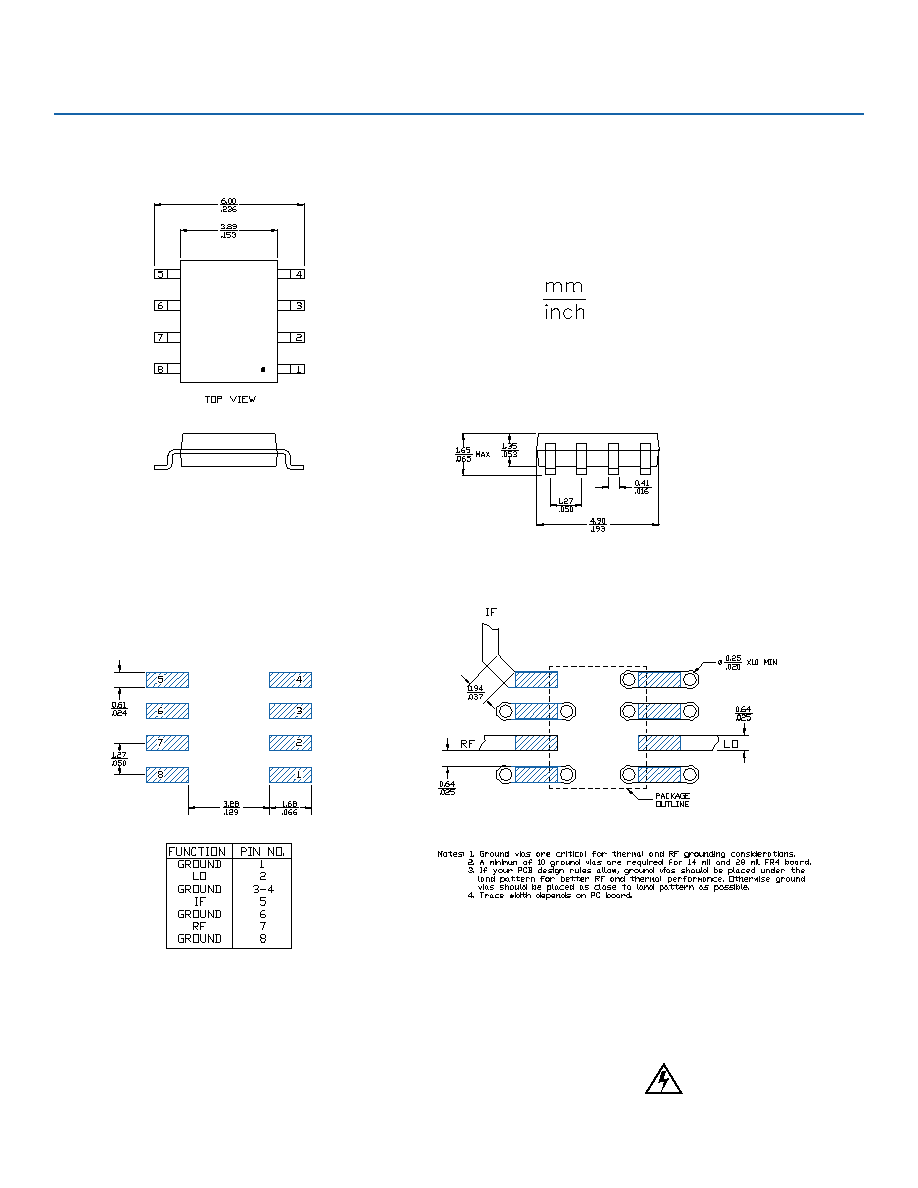
Outline Drawing
Land Pattern
Mounting Configuration