Document Outline
- WM8816
- Stereo Digital Volume Control
- Advanced Information, September 2000, Rev 1.1
- DESCRIPTION
- FEATURES
- APPLICATIONS
- BLOCK DIAGRAM
- PIN CONFIGURATION
- ORDERING INFORMATION
- PIN DESCRIPTION
- ABSOLUTE MAXIMUM RATINGS
- RECOMMENDED OPERATING CONDITIONS
- ELECTRICAL CHARACTERISTICS
- CONTROL INTERFACE TIMING DIAGRAM
- DEVICE DESCRIPTION
- REGISTER MAP
- TEST REGISTER
- PERFORMANCE GRAPHS
- RECOMMENDED EXTERNAL COMPONENTS
- RECOMMENDED EXTERNAL COMPONENTS VALUES
- PACKAGE DIMENSIONS

WM8816
Stereo Digital Volume Control
Advanced Information, September 2000, Rev 1.1
WOLFSON MICROELECTRONICS LTD
Lutton Court, Bernard Terrace, Edinburgh, EH8 9NX, UK
Tel: +44 (0) 131 667 9386
Fax: +44 (0) 131 667 5176
Email: sales@wolfson.co.uk
http://www.wolfson.co.uk
Advanced information data sheets contain
preliminary data on new products in the
pre-production phase of development.
Supplementary data will be published at a
later date.
2000 Wolfson Microelectronics Ltd
.
DESCRIPTION
The WM8816 is a highly linear stereo volume control for
audio systems. The design is based on resistor chains with
external op-amps, which provides flexibility for the supply
voltage, signal swing, noise floor and cost optimisation. The
gain of each channel can be independently programmed
from -111.5dB to +15.5dB through a digital serial control
interface.
Audible clicks on gain changes are eliminated by changing
gains only when a zero crossing has been detected in the
signal. The device also features peak level detection, which
can be used for Automatic Gain Control. The WM8816
operates from a single +5V supply and accepts signal input
levels up to �18V.
The WM8816 is available in a 16-pin SOIC package. It is
guaranteed over a temperature range of -40
�
to 85
�
C.
FEATURES
�
Gain range from -111.5dB to +15.5dB
�
0.5dB Gain step size
�
Total Harmonic Distortion 0.001% (100dB) typical
�
Crosstalk -110dB typical
�
Input signals up to �18V
�
Zero Detection for Gain Changes
�
Hardware and Software Mute
�
Power On/Off Transient Suppression
APPLICATIONS
�
Audio
Amplifiers
�
Consumer Audio / Entertainment Systems
�
Mixing
Desks
�
Audio Recording Equipment
BLOCK DIAGRAM
Zero
Crossing
Detector
Zero
Crossing
Detector
Peak
Level
Detector
Peak
Level
Detector
CSB (6)
MUTEB (8)
DATA (9)
CCLK (10)
LGND (5)
LIN (4)
DAC
(3) LFO
(2) LMO
RIN (13)
RGND (12)
(14) RFO
(15) RMO
(1)
AVDD
(16)
AGND
(7)
DVDD
(11)
DGND
+
-
+
-
LEFT OUT
RIGHT OUT
External Opamps
Control
WM8816
WM8816
Advanced Information
WOLFSON MICROELECTRONICS LTD
AI Rev 1.1 September 2000
2
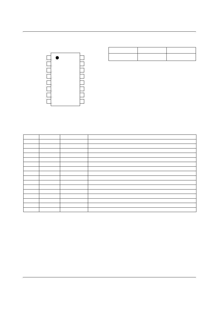
PIN CONFIGURATION
ORDERING INFORMATION
DEVICE
TEMP. RANGE
PACKAGE
XWM8816EDW
-40 to +85
o
C
16-pin SOIC (plastic)
10
9
14
13
12
11
5
6
7
1
2
3
4
CCLK
DGND
RGND
RIN
RFO
AGND
RMO
DVDD
CSB
LGND
LIN
LFO
AVDD
LMO
8
15
16
MUTEB
DATA
PIN DESCRIPTION
PIN
NAME
TYPE
DESCRIPTION
1
AVDD
Supply
Supply Voltage for Analogue Circuitry
2
LMO
Analogue Output
External Op-amp Inverting Input (Left Channel)
3
LFO
Analogue Input
External Op-amp Feedback Signal (Left Channel)
4
LIN
Analogue Input
Input Signal (Left Channel)
5
LGND
Analogue Input
Input Signal Ground (Left Channel)
6
CSB
Digital Input
Chip Select (active low)
7
DVDD
Supply
Supply Voltage for Digital Circuitry
8
MUTEB
Digital Input
Mute (active low)
9
DATA
Digital In / Out
Serial Interface Data Input / Output (tri-state)
10
CCLK
Digital Input
Serial Interface Clock
11
DGND
Supply
Digital Ground
12
RGND
Analogue Input
Input Signal Ground (Right Channel)
13
RIN
Analogue Input
Input Signal (Right Channel)
14
RFO
Analogue Input
External Op-amp Feedback Signal (Right Channel)
15
RMO
Analogue Output
External Op-amp Inverting Input (Right Channel)
16
AGND
Supply
Analogue Ground

Advanced Information
WM8816
WOLFSON MICROELECTRONICS LTD
AI Rev 1.1 September 2000
3
ABSOLUTE MAXIMUM RATINGS
Absolute Maximum Ratings are stress ratings only. Permanent damage to the device may be caused by continuously operating
at or beyond these limits. Device functional operating limits and guaranteed performance specifications are given under Electrical
Characteristics at the test conditions specified.
ESD Sensitive Device. This device is manufactured on a CMOS process. It is therefore susceptible to damage
from excessive static voltages. To optimise the distortion and noise performance of pins 3, 4, 13 and 14, the
on-chip ESD protection circuitry has been restricted, and consequently only achieves 300V when characterised
to the Human Body Model. Proper ESD precautions must be taken during handling and storage of this device.
As per JEDEC specification JESD22-A112-A, this product requires specific storage conditions prior to surface mount assembly. It
has been classified as having a Moisture Sensitivity Level of 3 and is therefore supplied in vacuum-sealed moisture barrier bags.
CONDITION
MIN
MAX
Input signal voltage
-20V
+20V
Positive supply voltage (AVDD to AGND, DVDD to DGND)
-0.5V
6V
Input voltage (all other pins)
-0.5V
AVDD + 0.5V
Operating temperature
-40
�
C
85
�
C
Storage temperature
-55
�
C
125
�
C
RECOMMENDED OPERATING CONDITIONS
PARAMETER
SYMBOL
TEST CONDITIONS
MIN
TYP
MAX
UNIT
Input signal voltage
-18
+18
V
Positive supply voltage
AVDD, DVDD
4.5
5
5.5
V
Negative supply voltage
AGND, DGND
0
V
Input signal grounds
LGND, RGND
0
V
Operating temperature
-20
60
60
�
C
ELECTRICAL CHARACTERISTICS
TEST CONDITIONS
AVDD = 5.0V, AGND = 0V, T
A
= 25�C, unless otherwise stated.
PARAMETER
SYMBOL
TEST CONDITIONS
MIN
TYP
MAX
UNIT
Analogue Inputs / Outputs
Input resistance
R
IN
For any gain
7
10
k
Input capacitance
C
IN
For any gain
2
pF
Input offset voltage
V
offset
External OP275
opamp, gain = 1
1
mV
Supply current
I
DD
From AVDD / AGND
2.5
5
mA
Power supply rejection ratio
(Note 1)
PSRR
From AVDD
80
dB
Gain Control
Gain range
G
-111.5
+15.5
dB
Gain step size
D
0.5
dB
Gain error (Note 1)
DE
Lowest gains
guaranteed by
design, not tested in
production.
0.5
dB
Gain match error (Note 1)
ME
Between channels
0.2
dB
Mute attenuation
MATT
113
dB
WM8816
Advanced Information
WOLFSON MICROELECTRONICS LTD
AI Rev 1.1 September 2000
4
TEST CONDITIONS
AVDD = 5.0V, AGND = 0V, T
A
= 25�C, unless otherwise stated.
PARAMETER
SYMBOL
TEST CONDITIONS
MIN
TYP
MAX
UNIT
Audio Performance
Gain = 0dB
13
N
Gain = -60dB
4
�
V rms
Noise (Note
1)
V
IN
= 0V, V
OUT
with OP275,
A-weighed
Gain = mute
2.5
Total Harmonic Distortion plus
Noise
THD+N
V
IN
= 1Vrms, gain=0dB,
V
OUT
with OP275,
DC to 20 kHz
0.001
(100)
%
(dB)
Dynamic Range (Note 1)
DR
120
130
dB
Crosstalk (Note 1)
CR
Between channels,
gain=0dB, f
IN
=1kHz
-100
-110
dB
Digital Inputs / Outputs
Input low voltage
V
IL
All digital inputs
0.3 DVDD
V
Input high voltage
V
IH
All digital inputs
0.7 DVDD
V
Output low voltage
V
OL
I
Load
= 2mA
0.4
V
Output high voltage
V
OH
I
Load
= 2mA
DVDD -0.4
V
Control Interface Timing
Clock Frequency
f
CCLK
1
MHz
Period of CCLK high
t
WHC
V
IH
to V
IH
500
ns
Period of CCLK low
t
WLC
V
IL
to V
IL
500
ns
Rise time of CCLK
t
RC
V
IL
to V
IH
100
ns
Fall time of CCLK
t
FC
V
IH
to V
IL
100
ns
Hold time, CCLK high to CSB low
t
HCHS
20
ns
Setup time, CSB low to CCLK
high
t
SSLCH
100
ns
Setup time, valid DATA to CCLK
high
t
SDCH
100
ns
Hold time, CCLK high to invalid
DATA
t
HCHD
100
ns
Setup time, CCLK low to valid
DATA
t
DCLD
Load = 100pF
200
ns
Hold time, CSB high or 16
th
CCLK low to invalid DATA
t
DSZ
Load = 3.3k
20
200
ns
Hold time, 16
th
CCLK high to
CSB high
t
HLCHS
200
ns
Setup time, CSB high to CCLK
high
t
SSHCH
200
ns
Note:
1.
Guaranteed by design.
Advanced Information
WM8816
WOLFSON MICROELECTRONICS LTD
AI Rev 1.1 September 2000
5
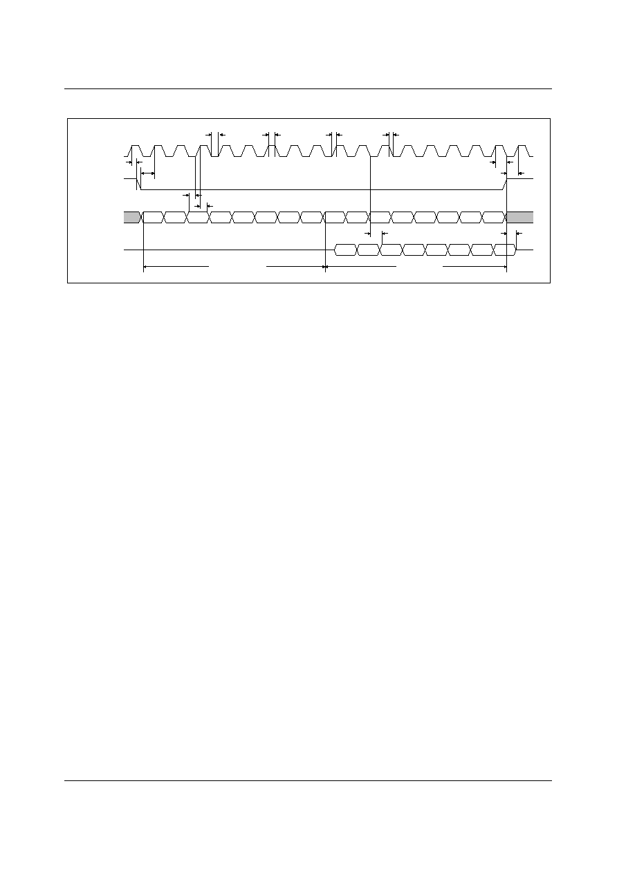
CONTROL INTERFACE TIMING DIAGRAM
CCLK
A7
DATA (IN)
A6
A5
A4
A3
A2
A1
A0
CSB
DATA (OUT)
D7
D6
D5
D4
D3
D2
D1
D0
D7
D6
D5
D4
D3
D2
D1
D0
t
SSLCH
t
HCSH
t
WLC
t
WHC
t
RC
t
FC
t
SDCH
t
HCHD
t
DCLD
t
DSZ
t
HLCHS
t
DSSHCH
ADDRESS BYTE
DATA BYTE
Figure 1 Control Interface Timing Diagram