 | –≠–ª–µ–∫—Ç—Ä–æ–Ω–Ω—ã–π –∫–æ–º–ø–æ–Ω–µ–Ω—Ç: UF4001-TB | –°–∫–∞—á–∞—Ç—å:  PDF PDF  ZIP ZIP |
UF4001 ≠ UF4007
1 of 3 © 2002 Won-Top Electronics
UF4001 ≠ UF4007
1.0A ULTRAFAST RECOVERY RECTIFIER
Features
!
Diffused
Junction
!
Low Forward Voltage Drop
!
High Current Capability A B A
!
High
Reliability
!
High Surge Current Capability
Mechanical Data
C
!
Case: Molded Plastic D
!
Terminals: Plated Leads Solderable per
MIL-STD-202, Method 208
!
Polarity:
Cathode
Band
!
Weight: 0.34 grams (approx.)
!
Mounting
Position:
Any
!
Marking: Type Number
Maximum Ratings and Electrical Characteristics
@T
A
=25∞C unless otherwise specified
Single Phase, half wave, 60Hz, resistive or inductive load.
For capacitive load, derate current by 20%.
Characteristic
Symbol
UF
4001
UF
4002
UF
4003
UF
4004
UF
4005
UF
4006
UF
4007
Unit
Peak Repetitive Reverse Voltage
Working Peak Reverse Voltage
DC Blocking Voltage
V
RRM
V
RWM
V
R
50
100
200
400
600
800
1000
V
RMS Reverse Voltage
V
R(RMS)
35
70
140
280
420
560
700
V
Average Rectified Output Current
(Note 1) @T
A
= 55∞C
I
O
1.0
A
Non-Repetitive Peak Forward Surge Current
8.3ms Single half sine-wave superimposed on
rated load (JEDEC Method)
I
FSM
30
A
Forward Voltage @I
F
= 1.0A
V
FM
1.0
1.3
1.7
V
Peak Reverse Current @T
A
= 25∞C
At Rated DC Blocking Voltage @T
A
= 100∞C
I
RM
5.0
100
µA
Reverse Recovery Time (Note 2)
t
rr
50
75
nS
Typical Junction Capacitance (Note 3)
C
j
20
10
pF
Operating Temperature Range
T
j
-65 to +125
∞C
Storage Temperature Range
T
STG
-65 to +150
∞C
*Glass passivated forms are available upon request
Note: 1. Leads maintained at ambient temperature at a distance of 9.5mm from the case
2. Measured with IF = 0.5A, IR = 1.0A, IRR = 0.25A. See figure 5.
3. Measured at 1.0 MHz and applied reverse voltage of 4.0V D.C.
WTE
POWER SEMICONDUCTORS
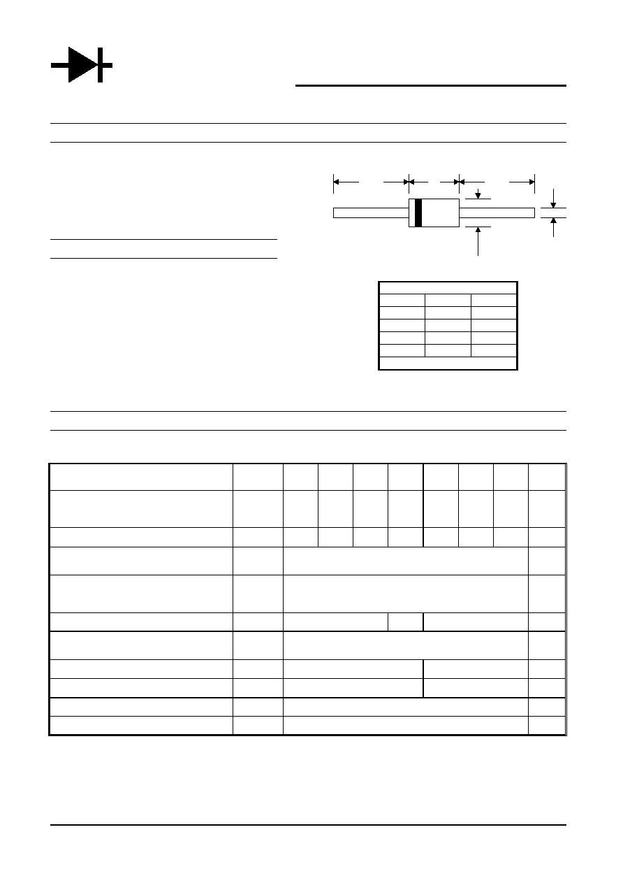
DO-41
Dim
Min
Max
A
25.4
--
B
4.06
5.21
C
0.71
0.864
D
2.00
2.72
All Dimensions in mm
0.01
0.1
1.0
10
0
0.2
0.4
0.6
0.8
1.0
1.2
1.4
I
,
INST
ANT
ANEOUS
FOR
W
ARD
CURRENT
(A)
F
V , INSTANTANEOUS FORWARD VOLTAGE (V)
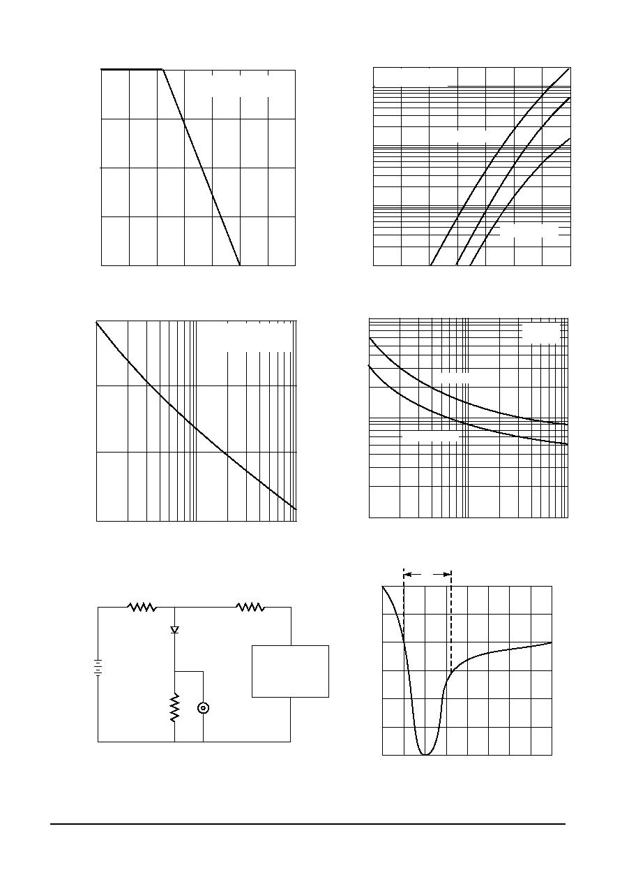
Fig. 2 Typical Forward Characteristics
F
UF4001 - UF4003
UF4005- UF4007
T = 25 C
Pulse width = 300 s
j
∞
µ
UF4004
10
20
30
0
1
10
100
I
,
PEAK
FOR
W
ARD
SURGE
CURRENT
(A)
FSM
NUMBER OF CYCLES AT 60Hz
Fig. 3 Peak Forward Surge Current
Pulse width
8.3 ms single half-sine-wave
(JEDEC method)
50V DC
Approx
50
NI (Non-inductive)
10
NI
1.0
NI
Oscilloscope
(Note 1)
Pulse
Generator
(Note 2)
Device
Under
Test
t
rr
Set time base for 5/10ns/cm
+0.5A
0A
-0.25A
-1.0A
Notes:
1. Rise Time = 7.0ns max. Input Impedance = 1.0M , 22pF.
2. Rise Time = 10ns max. Input Impedance = 50 .
Fig. 5 Reverse Recovery Time Characteristic and Test Circuit
(+)
(+)
(-)
(-)
1
10
100
1
10
100
C
,
CAP
ACIT
ANCE
(pF)
j
V , REVERSE VOLTAGE (V)
Fig. 4 Typical Junction Capacitance
R
UF4001 - UF4004
UF4005 - UF4007
T = 25 C
f = 1.0MHz
j
∞
0
0.25
0.50
0.75
1.00
0
25
50
75
100
125
150
175
I
,
A
VERAGE
FWD
RECTIFIED
CURRENT
(A)
(A
V)
T , AMBIENT TEMPERATURE ( C)
Fig. 1 Forward Current Derating Curve
A
∞
Single phase half wave
Resistive or Inductive load
UF4001 ≠ UF4007
2 of 3 © 2002 Won-Top Electronics
UF4001 ≠ UF4007
3 of 3 © 2002 Won-Top Electronics
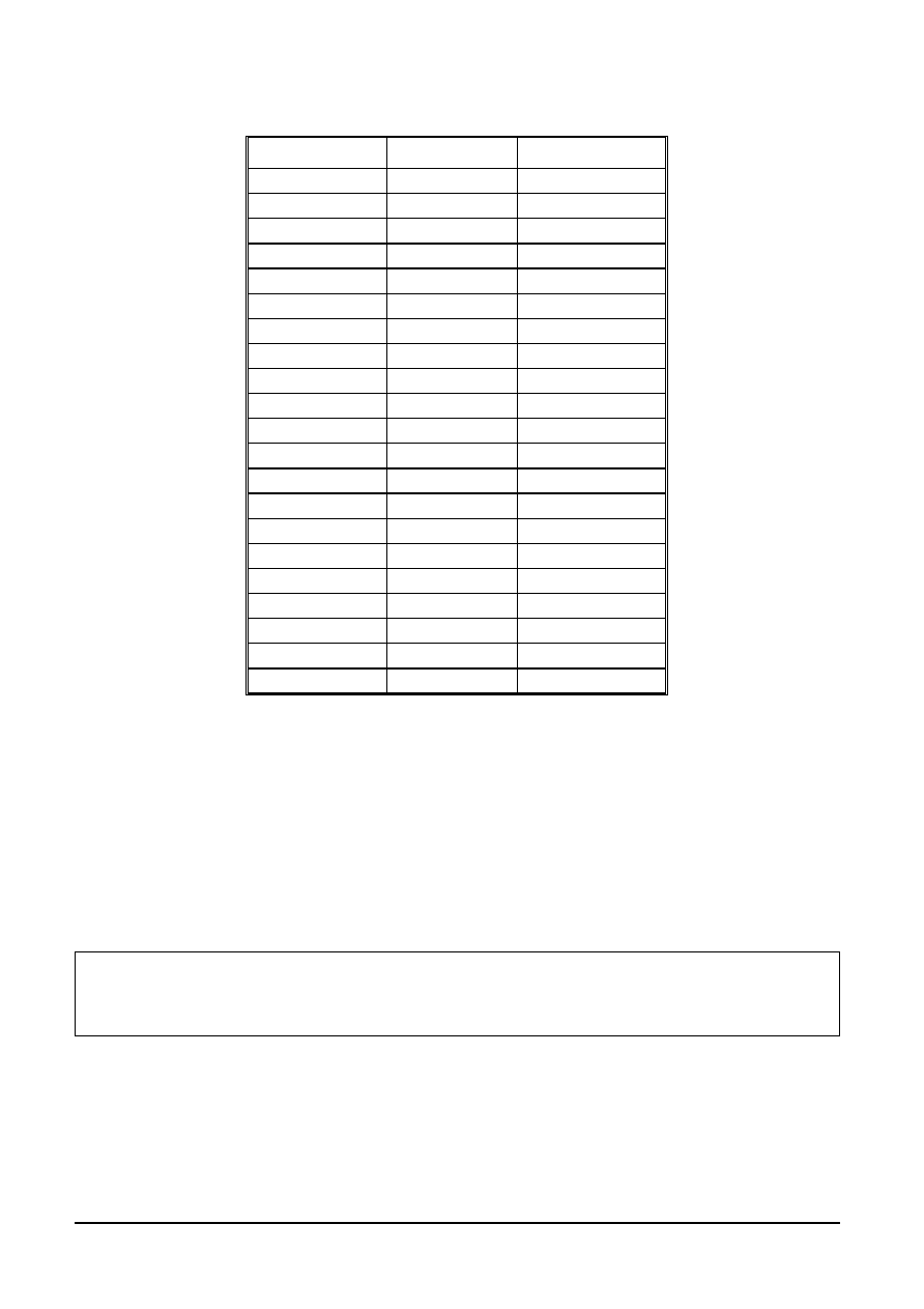
ORDERING INFORMATION
Product No.
!
!
!
!
Package Type
Shipping Quantity
UF4001-T3
DO-41
5000/Tape & Reel
UF4001-TB
DO-41
5000/Tape & Box
UF4001
DO-41
1000 Units/Box
UF4002-T3
DO-41
5000/Tape & Reel
UF4002-TB
DO-41
5000/Tape & Box
UF4002
DO-41
1000 Units/Box
UF4003-T3
DO-41
5000/Tape & Reel
UF4003-TB
DO-41
5000/Tape & Box
UF4003
DO-41
1000 Units/Box
UF4004-T3
DO-41
5000/Tape & Reel
UF4004-TB
DO-41
5000/Tape & Box
UF4004
DO-41
1000 Units/Box
UF4005-T3
DO-41
5000/Tape & Reel
UF4005-TB
DO-41
5000/Tape & Box
UF4005
DO-41
1000 Units/Box
UF4006-T3
DO-41
5000/Tape & Reel
UF4006-TB
DO-41
5000/Tape & Box
UF4006
DO-41
1000 Units/Box
UF4007-T3
DO-41
5000/Tape & Reel
UF4007-TB
DO-41
5000/Tape & Box
UF4007
DO-41
1000 Units/Box
Products listed in bold are WTE Preferred devices.
!
T3 suffix refers to a 13" reel. TB suffix refers to Ammo Pack.
Shipping quantity given is for minimum packing quantity only. For minimum order
quantity, please consult the Sales Department.
Won-Top Electronics Co., Ltd (WTE) has checked all information carefully and believes it to be correct and accurate. However, WTE cannot assume any
responsibility for inaccuracies. Furthermore, this information does not give the purchaser of semiconductor devices any license under patent rights to
manufacturer. WTE reserves the right to change any or all information herein without further notice.
WARNING: DO NOT USE IN LIFE SUPPORT EQUIPMENT. WTE power semiconductor products are not authorized for use as critical components in life
support devices or systems without the express written approval.
We power your everyday.
Won-Top Electronics Co., Ltd.
No. 44 Yu Kang North 3rd Road, Chine Chen Dist., Kaohsiung, Taiwan
Phone: 886-7-822-5408 or 886-7-822-5410
Fax: 886-7-822-5417
Email: sales@wontop.com
Internet: http://www.wontop.com