
XECOM
(1)
XE0017
XE0017
05/99
Low-Profile, V.34 Compatible Telephone Line Interface
Description
The XE0017 is fully-integrated, low-profile, high-
performance telephone line interface module. It
complies with FCC Part 68 requirements for direct
connection to the public switched telephone network.
The XE0017 meets the technical requirements for data
transmission at rates up to 33,600 bps. It is also suitable
for fax and voice communications. The XE0017 was
specifically designed to be compatible with Rockwell
Socket Modems.
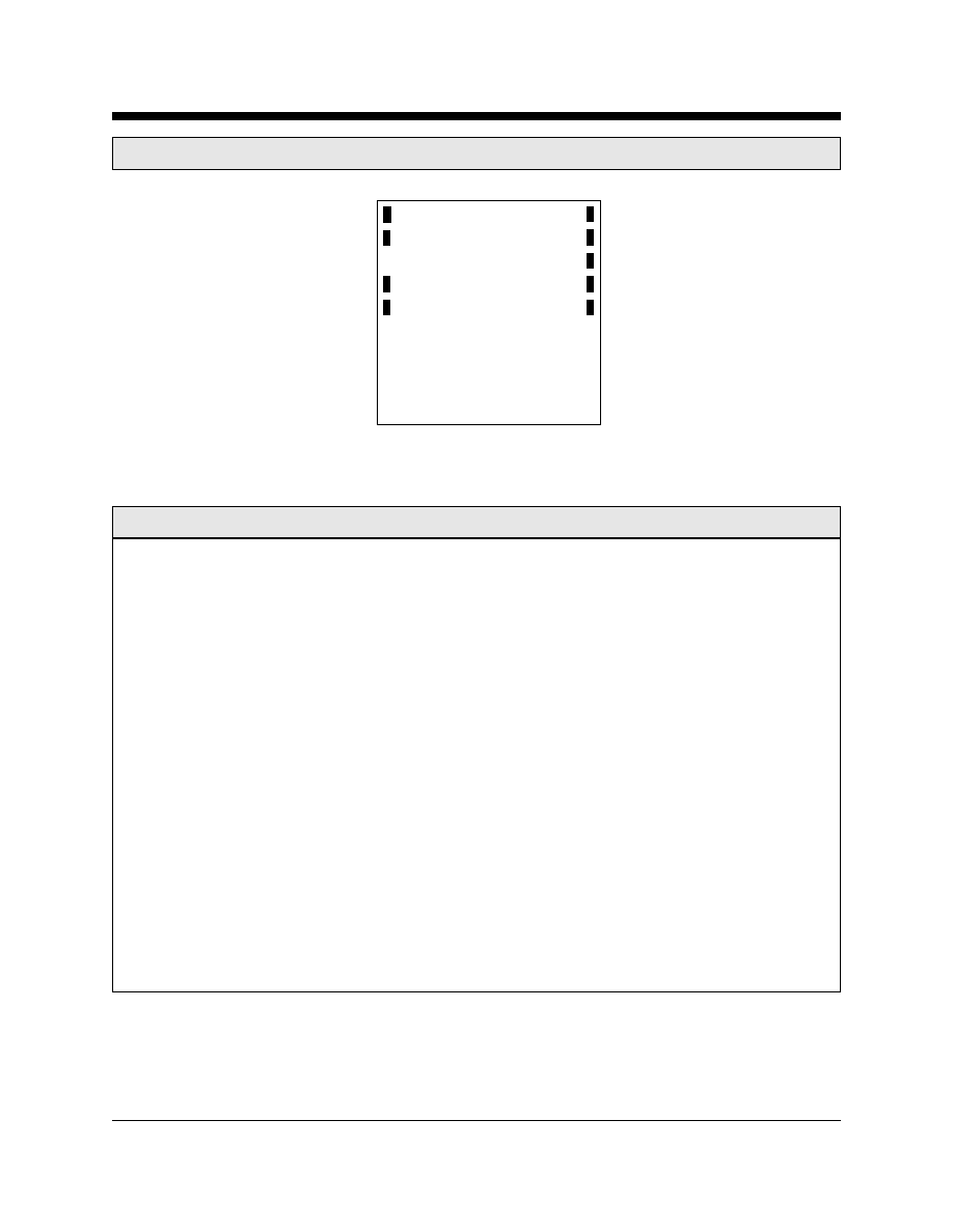
The XE0017 is a complete DAA. It includes a low
distortion telephone line transformer, ring detector,
hookswitch and 2-4 wire convertor. The 2-4 wire
convertor separates transmit and receive signals. The
XE0017 operates from a single +5 volt supply and fits in
a 0.260 inch high package.
Features
*
Small Size:
0.95 inches by 0.925 inches by 0.260 inches
*
FCC Part 68 Compliant
*
V.34 compatible
*
Compatible with Rockwell's Socket Modems
*
2 to 4 Wire Converter
*
Ring Detection
*
Single +5V Operation
*
Hookswitch Control
*
UL and CSA Recognized
*
Extended Temperature Range Parts available
SURGE
AND
PROTECTIVE
NETWORK
LINE
CURRENT
CIRCUIT
OH
RI
RING
DETECT
CIRCUIT
RING
TIP
2 TO 4
WIRE
CONVERTER
HOOK-
SWITCH
CONTROL
Tx
Rx
XE0017 Block Diagram

XECOM
(2)
XE0017
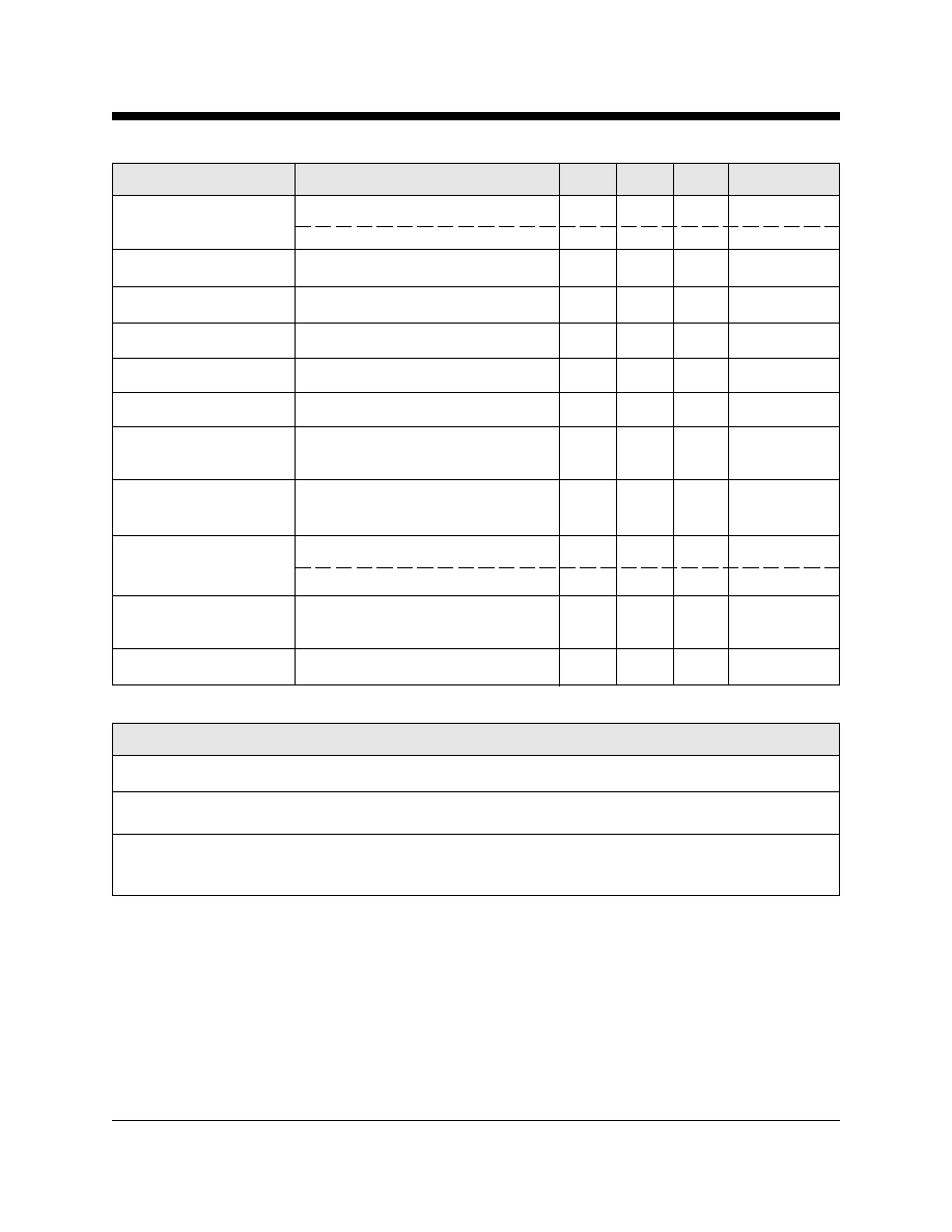
XE0017 Mechanical Specifications
Pins are .010 by .020 inches.
All Pins are tin-plated for solderability
Inches
Millimeters
Dim
Min
Max
Min
Max
A
0.905
0.945
22.99
24.00
B
0.930
0.970
23.62
24.64
C
0.250
0.270
6.35
6.86
D
0.790
0.810
20.07
20.57
E
0.390
0.410
9.91
10.41
F
0.200
0.220
5.08
5.59
G
0.065
0.085
1.65
2.16
H
0.065
0.085
1.65
2.16
J
0.090
0.110
2.29
2.79
K
0.430
0.450
10.92
11.43
A
B
Denotes Pin 1
C
D
G
J
H
E
F
K
XE0017 Typical Connection Diagram
Modem Analog
Front End
XE0017
9 Gnd
Tip 1
8 Tx
Ring 2
7 VCC
6 N/C
OH 3
5 Rx
/RI 4
RJ11
3
4
Transmit
Receive
/Ring
OHRLY
+5 Volts
RV1
R1
R2
FB1
FB2
C1
C2
Recommended Parts
Designation
Description
C1, C2
470 pFd, 3000 Volts (Sprague Part Number 30GA-T47)
R1, R2
10 ohm, 1/2 Watt
FB1, FB2
Ferrite Bead (TDK Part Number CB30-453215B)
RV1
Sidactor, Minimum breakover 260 Volts (Teccor Part Number P3100BA70)
XECOM
(3)
XE0017
XE0017 Pin Descriptions
PIN
NAME
DESCRIPTION
1
Ring
Ring connection to the phone line (RJ11 Pin 4). The Ring pin has 1500 volts isolation
from the rest of the circuitry. This isolation must be preserved throughout the system.
The XE0017 is not polarity sensitive.
2
Tip
Tip Connection to the phone line (RJ11 Pin 3). The Tip pin has 1500 volts isolation
from the rest of the circuitry. This isolation must be preserved throughout the system.
3
OH
Hookswitch relay control. A high on OH closes the internal relay and connects the equip-
ment to the telephone line.
4
/RI
Ring Indicate, output, active low, TTL, indicates that the modem is receiving a ring sig-
nal. /RI provides a square wave representation of the Ring signal present at Tip and
Ring.
5
RX
RX provides the analog output signal from the 2-4 wire converter of the XE0017.
6
N/C
No Connection
7
VCC
+5 Volt power source
8
TX
TX provides the analog input signal to the 2-4 wire convertor of the XE0017.
9
GND
Ground
XE0017 Pin Configuration
1
2
3
4
9
8
7
6
5
Gnd
TX
VCC
N/C
RX
Tip
Ring
OH
/RI
XE0017
XECOM
(4)
XE0017
XE0017 Electrical Specifications
(VCC= 5 Volts + 10%, Ta 0 to 70 C)
Parameter
Conditions
Min
Typ
Max
Units
Power Supply Current
XE0017 Off-hook
10
15
mA
XE0017 On-hook
5
10
mA
XE0017 Tx Insertion loss
600 Ohm Impedence, 1800 Hz
6.0
6.5
7.0
dB
XE0017 Rx Insertion loss
600 Ohm Impedance, 1800 Hz
-0.50
0
0.50
dB
Line Impedance
At 1800 Hz
540
600
660
ohms
XE0017 Transhybrid Loss
600 Ohm Impedance, 1800 Hz
18
23
dB
Total Harmonic Distortion
600 Ohm Impedance, 1800 Hz
-72
-76
dB
Ring Detect Sensitivity
Min. AC voltage between Tip &
38
150
Vrms
Ring Type B ringer
Ring Indicate Output
Ring Voltage present on Tip
0.2
0.5
Volts
Voltage
& Ring
Hook-Switch Control
ON: (off-hook)
2.0
3.0
Volts
Voltage
OFF: (on-hook)
0.2
0.5
Volts
Loop Current Switch
0.3
0.5
mA
Control Current
Loop Current
Off-hook
20
100
mA
Abosulte Maximum Ratings
Storage Temperature
-25
o
C to +85
o
C
Operating Temperature Range
0
o
C to +70
o
C
Maximum Lead Temperature
260
o
C
(soldering 2 seconds per wave)

XECOM
(5)
XE0017
When developing a product to be connected to the telephone line, it is necessary to use a circuit described as a Data Access
Arrangement (DAA) which is approved by the appropriate governmental agency. In the US, for example, this agency is the Federal
Communications Commission (FCC), while in Canada it is the Department of Communications (DOC). These agencies test and
approve the product to ensure that it meets their specifications, thereby protecting the telephone system from damage and
protecting the user from high voltage transients (such as lightning strikes) which may come down the telephone line.
The XE0017 has been designed to meet all FCC Part 68 requirements for hazardous voltage, surge protection and leakage current.
If the system developed transmits data, or DTMF tones on the telephone line, the user must certify that the signals transmitted meet
basic FCC requirements for maximum transmission levels, out of band energy and billing delay. Full details may be obtained from
the FCC under Part 68 of the FCC Rules and Regulations, or in Title 47 of the Code of Federal Regulations, however the basic
requirements are as follows:
1. Maximum Transmit Level
For the normal "permissive" (standard) telephone line, equipment which transmits data (such as a modem) must not exceed a
transmission level of -9 dBm.
2. Out of Band Energy
Data equipment must not transmit "out of band" energy on the telephone line which exceeds the following limits:
Frequency
Range
Max. Power
200Hz
to
3990Hz
-9 dBm
3990Hz
to
4005Hz
-27 dBm
4005Hz
to
16kHz
-16 dBm
8kHz
to
94kHz
-47 dBm
86kHz
to
270kHz
-46 dBm
270kHz
to
6MHz
-6 dBm
3. DTMF Transmission Level
If the system is capable of DTMF dialing, the maximum DTMF transmission level must be less than 0 dBm averaged over a 3
second interval.
4. Billing Delay
A delay of 2 seconds or greater is required after the time the XE0017 is taken "off hook" and before any information is transmitted.
This is required to ensure that billing information may be exchanged between telephone company central offices without
interference.
The user of the XE0017 must certify to the FCC that the final system meets the requirements of Part 68 which include the criteria
above as well as the high voltage protection provided by the XE0017. This is generally accomplished through an independent
testing lab which tesst the System and submits the proper paperwork to the FCC for approval. Since the XE0017 already comply
with FCC Part 68 rules, this is a relatively simple proces
s.
FCC Information