
XECOM
(1)
XE0052
XE0052S &XE0052T
5/99
Slim V.34 Telephone Line Interface with 2/4 Wire Hybrid
Description
The XE0052S and XE0052T are compact telephone in-
terface modules which support V.34 communications at
data rates to 33,600 bps yet are just 0.31 inches thick
and comply with FCC Part 68 Rules for connection to
the public telephone network.
The XE0052S and XE0052T are complete DAAs.
They include the 2-4 wire convertor to separate trans-
mit and receive signals, ring detection, and the switch
hook to control line access. The two models differ only
in their RI outputs. The XE0052S has an integrated RI
output which remains low for the duration of the ring.
The XE0052T RI output is not integrated and provides
a pulse train at twice the ring frequency.
Xecom offers two mechanical variations for each of the
XE0052S and XE0052T. The XE0052S1/T1 mount
vertically to consume minimal board space. The
XE0052S2/T2 mount horizontally to maintain a low
profile. Both versions are electrically identical and
share the same pin configuration.
Features
*
Small Size: just 1.5" by 0.5" by 0.32";
*
FCC Part 68 Compliant;
*
Internal 2-4 wire convertor separates transmit and
receive signals
*
Two Ring Detect Options;
XE0052S1/S2: - Continuous Low Level
XE0052T1/T2 - Ring Signal Pulses
*
Single +5V Operation;
*
Hookswitch Control
*
Compatible with V.34 data transfer
*
Two Mechanical Variations
XE0052S1/T1 - Vertical Mount
XE0052S2/T2 - Horizontal Mount
SURGE
AND
PROTECTIVE
NETWORK
LINE
CURRENT
CIRCUIT
OH
RI
RING
DETECT
CIRCUIT
RING
TIP
2 TO 4
WIRE
CONVERTER
HOOK-
SWITCH
CONTROL
Tx
Rx
XE0052 Block Diagram

XECOM
(2)
XE0052
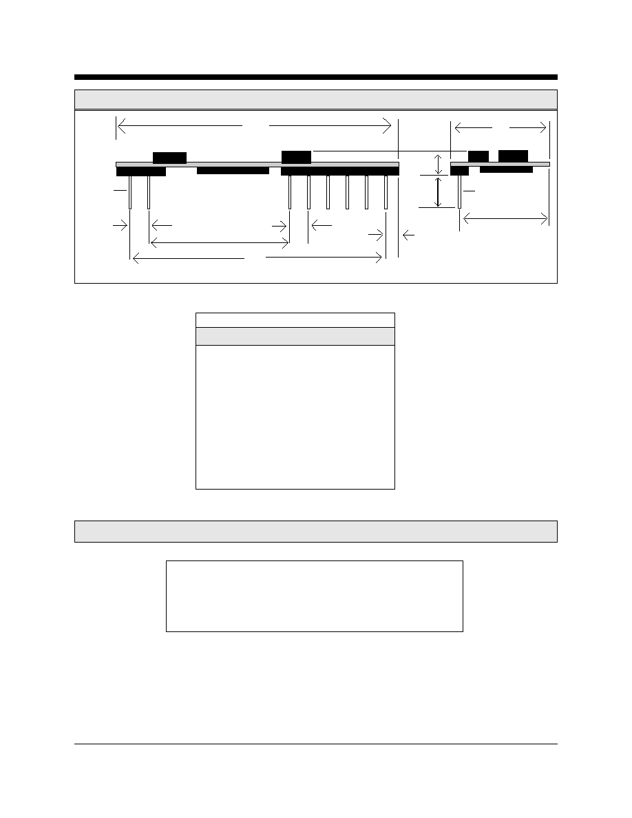
XE0052S1 and XE0052T1 Mechanical Specifications
Vertical Package
Inches
Millimeters
Dim
Min
Max
Min
Max
A
0.300
0.320
7.62
8.13
B
0.490
0.510
12.45
12.95
C
1.490
1.510
37.85
38.35
D
0.040
0.060
1.02
1.52
E
1.390
1.410
35.31
35.81
F
0.090
0.110
2.29
2.79
G
0.790
0.810
20.07
20.57
H
0.125
0.200
3.18
5.08
B
C
D
E
F
G
H
A
F
Pin 1
Pin 1
XECOM
(3)
XE0052
XE0052S2 and XE0052T2 Mechanical Specifications
Horizontal Package
B
C
D
E
F
G
H
A
F
I
Pin 1
Pin 1
Inches
Millimeters
Dim
Min
Max
Min
Max
A
0.490
0.510
12.45
12.95
B
0.320
0.330
8.13
8.38
C
1.490
1.510
37.85
38.35
D
0.040
0.060
1.02
1.52
E
1.390
1.410
35.31
35.81
F
0.090
0.110
2.29
2.79
G
0.790
0.810
20.07
20.57
H
0.125
0.200
3.18
5.08
I
0.440
0.450
11.18
11.43
XE0052 Pin Configuration (Top view)
8
7
6
5
4
3
2
1
O
O
O
O
O
O
O
O
/RI
RX VCC Gnd
TX
OH
Tip Ring

XECOM
(4)
XE0052
XE0052 Pin Descriptions
1
Ring
---
Ring connection to the phone line (RJ11 Pin 4). The Ring pin has 1500 volts isolation
from the rest of the circuitry. This isolation must be preserved throughout the system.
2
Tip
---
Tip Connection to the phone line (RJ11 Pin 3). The Tip pin has 1500 volts isolation
from the rest of the circuitry. This isolation must be preserved throughout the system.
3
OH
I
Hookswitch relay control. A high on OH closes the internal relay and connects the
equipment to the telephone line.
4
TX
I
TX provides the analog input signal to the 2-4 wire convertor of the XE0052S. TX
uses a 2.5 volt reference signal and therefore must be capacitively coupled to the host
equipment.
5
GND
--
Ground
6
VCC
---
+5 Volts supply power
7
RX
O
RX provides the analog output signal from the 2-4 wire converter of the XE0052S. RX
uses a 2.5 volt reference signal and therefore must be capacitively coupled to the host
equipment.
8
/RI
O
Ring Indicate, output, active low, TTL. On the XE0052S a low on /RI indicates the
modem is receiving a ring signal. The XE0052T provides a pulse string at twice the
ring frequency when a ring is detected.
Pin
Name
I/O
Description
XE0052 Absolute Maximum Ratings
Storage Temperature
-25
O
C to +85
O
C
Operating Temperature Range
0
O
C to +70
O
C
Maximum Lead Temperature
260
O
C
(soldering 2 seconds per wave)

XECOM
(5)
XE0052
XE0052 Electrical Specifications
(VCC = 5V + 10%, Ta = 0 to 70C)
Power Supply Current
Ring Indicate Active
10
15
mA
Transmit Insertion loss
600 Ohm Impedence, 1000 Hz
0
dB
Receive Insertion loss
600 Ohm Impedance, 1000 Hz
0
dB
Line Impedance
At 1000 Hz
540
600
660
Ohms
Transhybrid Loss
Attenuation between transmiter input and
10
18
dB
receiver output at 1KHz with 600 ohm
line termination
Ring Detect Sensitivity
Min. AC voltage between Tip & Ring
38
Vrms
Type B ringer
Ring Detect Peak Current
Ringing voltage of 40 Vrms applied
100
uA
between Tip & Ring
Ring Detect Idle Current
No Ringing Voltage present
10
uA
Ring Indicate Output
Ring Voltage present on Tip and Ring
0.2
0.5
Volts
Loop Current Switch
ON: (off-hook)
2.0
3.0
Volts
Control Voltage
OFF: (on-hook)
0.2
0.5
Volts
Loop Current Switch
Off-Hook
0.5
mA
Control Current
Parameter
Conditions
Min
Typ
Max Units
XE0052 Typical Connection Diagram
Modem Analog
Front End
XE0052S or XE0052T
RJ11
4
3
/Ring
Receive
Transmit
OHRLY
+5 Volts
10 ohms, 1/2 W
470 pFd
3000 Volts
470 pFd
3000 Volts
FerriteBead
10
m
Fd
10
m
Fd
FerriteBead
Teccor
P3100SB
10 ohms, 1/2 W
/RI Rx Vcc Gnd Tx OH
Tip Ring
8
7
6
5
4
3
2
1