XECOM
(1)
XE2420G
XE2420G
September 2003
Smallest World-Wide 2400 BPS Modem
Description
Xecom's XE2420G offers unprecedented design
flexibility. It provides a global common communications
solution in the smallest available package. The
XE2420G fits a standard 68-Pin PLCC socket and can be
socketed or soldered onto the board in an automated
assembly process. The XE2420G allows incorporation of
a dial-up access where no other modem will fit.
The surface mount package and small size of the
XE2420G are particularly impressive because it is a
complete modem. The DAA, RAM, Crystal; everything
is included. Like all Xecom modems, the XE2420G
includes transferrable FCC Part 68 Registration.
No 2400 BPS modem incorporates more features than
the XE2420G. The XE2420G is one of the few low-speed
modems available with built-in error correction . The
XE2420G incorporates both a sleep mode and power
down mode making it ideal for battery powered
applications. The XE2420G also incorporates Handset
Interrupt to prevent conflicts in shared line applications.
Features
* Small Size: The HyPLCCTM measures less than 1 inch
by 1 inch square and 0.350 inches thick
* Surface-mountable: The HyPLCCTM package is
equivalent to a 68-Pin PLCC device.
* Data transfer from 300 to 2400 BPS using V.22bis,
V.22, V.23, V.21, Bell 212A, and Bell 103 Protocols
* Modem Control and Configuration via industry
standard AT Commands.
* Supports V.42 and MNP error correction;
* Complete integrated solid-state DAA includes, Ring
Detect, Loop Current Holding Circuit, Hook Switch
and Metallic Surge Protection;
* User Transferrable FCC Part 68 Registration
* Complies with telephone networks around the world.
* UL60950 Recognition
* Handset Interrupt detects parallel telephone pick -up
* Low Power operation, typically less than 100 mW,
includes automatic sleep mode and power down
operation;
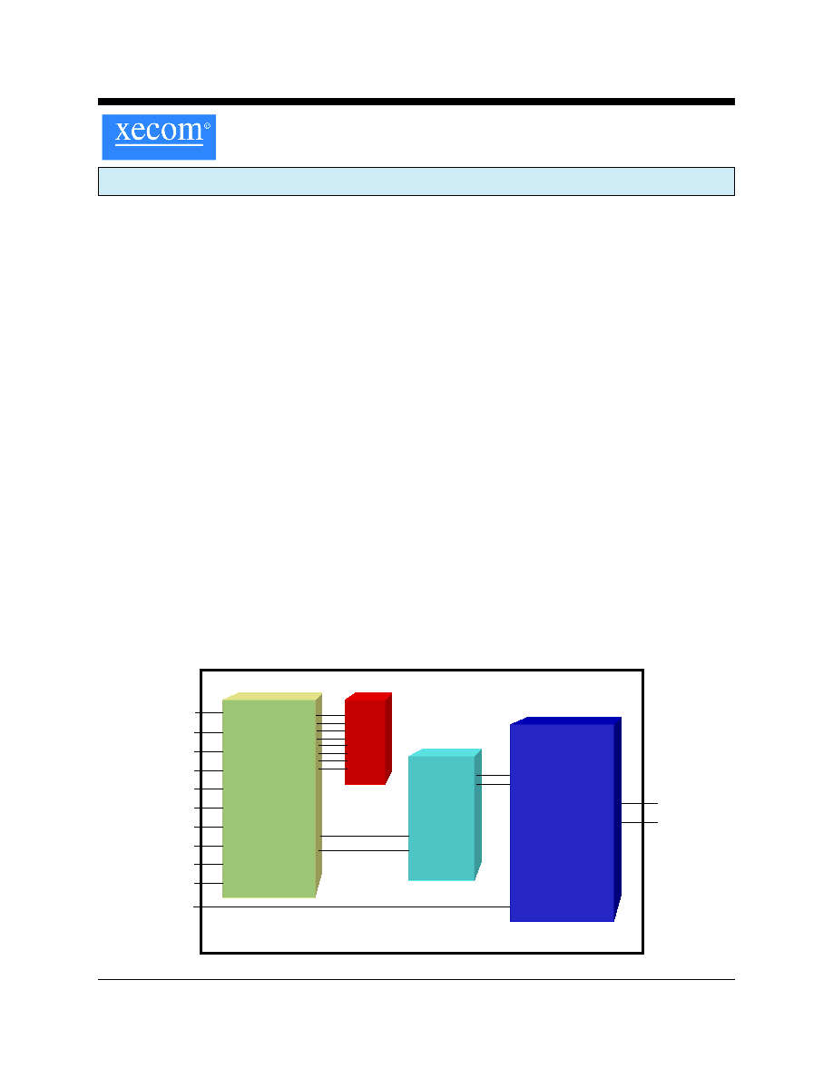
XE2420G BLOCK DIAGRAM
Modem
Controller
R
A
M
Analog
Front
End
Tip
Ring
/Reset
/TXD
/RXD
/RTS
/DSR
/DCD
/CTS
/DTR
/RI
/INT
SPKR
Global
Telephone
Line
Interface
(DAA)

XECOM
(2)
XE2420G
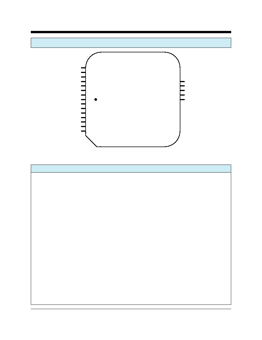
XE2420G Mechanical Specifications
a
b
c
d
c
f
g
e
e
45
O
i
(TOP)
Inches
Millimeters
Dimension
Min
Typ
Max
Min
Typ
Max
a
0.345
0.350
0.355
8.76
8.89
9.02
b
0.985
0.990
0.995
25.02
25.15
25.27
c
0.950
0.955
0.960
24.13
24.26
24.38
d
0.910
0.920
0.930
23.11
23.37
23.62
e
0.045
0.050
0.055
1.15
1.27
1.40
f
0.695
0.700
0.705
17.65
17.78
17.91
g
0.195
0.200
0.205
10.03
10.16
10.29
i(radius)
0.015
0.020
0.025
0.13
0.25
0.38
i
i
.050"
XECOM
(3)
XE2420G
XE2420G Pin Configuration
Pin Descriptions
PIN NAME
DESCRIPTION
1
/DCD
/DCD is an active low output from the modem. /DCD indicates the presence of a valid carrier
signal.
2
/CTS
/CTS is an active low output from the modem. When hardware flow control is active, the modem
asserts /CTS to indicate that it can accept data from the terminal equipment on /TXD.
3
/RESET
/RESET is an active low input which initiates a modem hardware reset. /RESET must be active for
a minimum of 100 milliseconds for a proper modem reset sequence. No external reset is required;
if none is used the /RESET signal should be left open.
4
/DSR
/DSR is active low output from the modem. /DSR is forced active.
5
/RTS
/RTS is an active low input to the modem. When hardware flow control is active, /RTS indicates
to the modem that the host has data to send.
6
/DTR
/DTR is an active low input to the modem. The operation of /DTR is controlled by bit 15 of
register U70 and is normally disabled. When enabled /DTR indicates the Host is ready to
communicate. If /DTR is removed while the modem is on-line it will exit data mode and enter
command mode.
7
/RXD
/RXD provides the path for received data and modem responses to be sent from the modem to
the host terminal equipment.
8
/TXD
/TXD provides the path for transmitted data and modem commands to be passed from the host
terminal equipment to the modem.
/DCD
/CTS
/RES ET
/DS R
/RTS
/DTR
/RXD
/TXD
/RI
GND
SPKR
N/C
/INT
VCC
N/C
1
2
3
4
5
6
7
8
9
10
11
12
13
14
15
24
23
22
21
20
19
18
17
16
RING
N/C
TIP
N/C
NP
NP
NP
NP
NP
Top

XECOM
(4)
XE2420G
9
/RI
The /RI signal reports on the presence of an incoming ring signal. When a ring occurs across
Tip and Ring, the /RI output goes low and toggles with the cadence of the ring signal.
10
Ground
Ground provides the reference voltage for all host interface signals.
11
SPKR
SPKR allows connection of a speaker to monitor modem operations. SPKR cannot directly drive
a speaker. An amplifier with a minimum input impedance of 300 ohms is required. The signal on
SPKR is controlled by the ATM command.
12
N/C
No internal connection
13
/INT
/INT provides an active low hardware interrupt signal from the XE2420G. The operation of this
interrupt pin is programmable using the modem's register U70.
14
VCC
VCC provides 3.3 volt power to the modem.
15
N/C
No internal connection
16-19
NP
No Pin
20-21
N/C
No internal connection
22
Tip
The Ring and Tip signals provide modem the connection to the telephone line. FCC Part 68
Rules require a 1500 volt isolation barrier between the telephone line and all other circuits. This
isolation must be preserved throughout the system.
The telephone company places a DC "Battery" voltage across Tip and Ring on all public switched
telephone lines. The XE2420G will operate regardless of the polarity of this "Battery" voltage.
The "Battery" voltage drives up to 100 milliamps of DC loop current.
UL60950 requires minimum creepage and clearances distances be maintained between the Tip
and Ring traces and all other circuits. Clearance is the shortest distance between conductive
circuits; creepage is the distance between conductive surfaces along the surface
23
N/C
No internal connection, To prevent damage in case of voltage surges on the telephone line, we
recommend that nothing be connected to this pin.
24
Ring
The Ring and Tip signals provide modem the connection to the telephone line. FCC Part 68
Rules require a 1500 volt isolation barrier between the telephone line and all other circuits. This
isolation must be preserved throughout the system.
The telephone company places a DC "Battery" voltage across Tip and Ring on all public switched
telephone lines. The XE2420G will operate regardless of the polarity of this "Battery" voltage.
The "Battery" voltage drives up to 100 milliamps of DC loop current.
UL60950 requires minimum creepage and clearances distances be maintained between the Tip
and Ring traces and all other circuits. Clearance is the shortest distance between conductive
XE2420G Pin Descriptions (continued)
PIN NAME
DESCRIPTION
XECOM
(5)
XE2420G
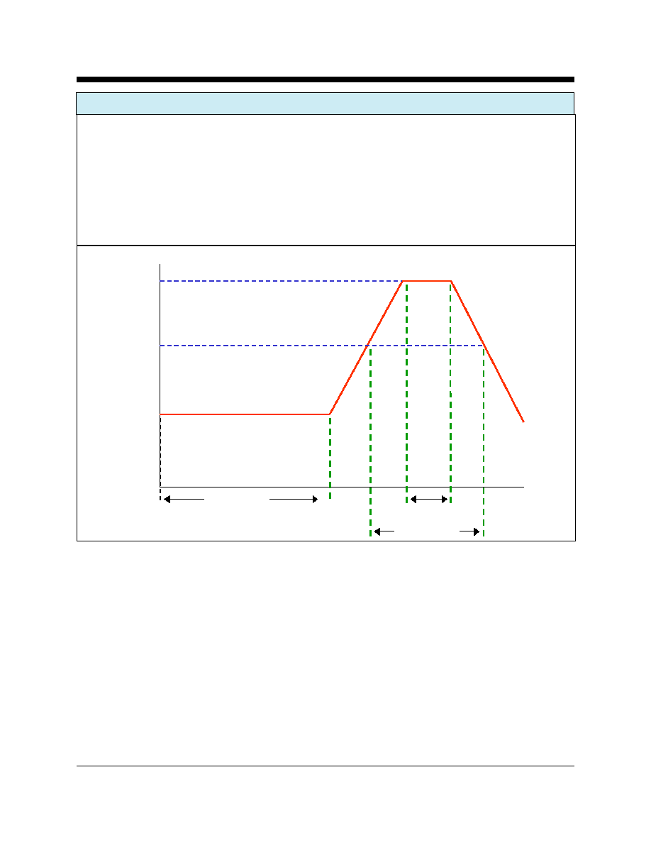
XE2420G Soldering Instructions
The XE2420G is subject to damage if over-exposed to heat during solder reflow operations. Following the soldering
instructions below will ensure that the process of soldering the module to the board does not damage the modem.
The XE2420G must not be exposed to direct Infrared (IR) heating. If your process includes direct IR heating, you
must shield the XE2420G from the infrared rays.
Maximum Temperature
220
O
C
Maximum Time at 220
O
C
20 Seconds
Maximum Time above Eutectic (180
O
C)
90 Seconds
Maximum Preheat Dwell Time
180 Seconds
Maximum Recommended Solder Temperature Profile
220
O
C
180
O
C
150
O
C
180 sec. max.
90 sec. max.
20 sec. max.