XECOM
(1)
XE900M
XE900M
March 2003
XE900M 900 MHz Smart Transceiver for Base Access System
Description
Xecom combines a micro-controller and a 900 MHz
transceiver to create the XE900M, Smart Transceiver.
The XE900M can communicate with another Smart
Transceiver or with Xecom's XE924M Base Access
Point. The Base Access Point connects multiple remote
systems to a single dial-up telephone line. The XE900M
supplies wireless connectivity through an easy-to-use
serial component.
Integrating the XE900M Smart Transceiver is as easy
as integrating a serial modem into your system. The
XE900M interfaces to the system host through a TTL
level serial interface. The designer controls the wireless
link by manipulating modem-like AT commands provided
in the Smart Transceiver.
The XE900M uses 126 user-selectable communications
channels in the 900 MHz ISM band. This creates a
flexible communications platform for simple point-to-
point communications between Smart Transceivers or a
complete Base Access Network with multi-point wireless
communications and Dial-up modem operation.
Features
* Small Size: 2.75" by 1.38: by 0.4"
* Control and Configuration of the Wireless Link
modem-like AT Commands.
* 126 Carrier Frequencies from 902.5 to 927.5 MHz on
ISM Band
* SensoronAir
TM
allows direct connection of sensors
to the Smart transceiver
* Wireless Range; maximum 150 Feet
* Wireless Data Rate 9600 BPS, half-duplex
* Integrated communications controller regulates
the wireless communications, error correction and
host interface.
* FCC Part 15 Compliance
Preliminary
System A
XE900M
Equipped
XE924M
Base Access
Point
Dial-up
Telephone
Line
System B
XE900M
Equipped
System C
XE900M
Equipped
900MHz Smart Transceiver Applications
900MHz Base Access System
Point to Point Wireless Connection
System A
XE900M
Equipped
System B
XE900M
Equipped
System Host
Micro-Controller
System Host
Micro-Controller

XECOM
(2)
XE900M
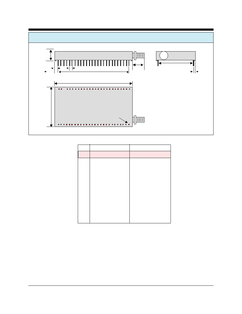
XE900M MECHANICAL SPECIFICATIONS
Inches
MM
PIN
MIN
MAX
MIN
MAX
A
2.740
2.760
69.60
70.10
B
0.400
0.420
10.16
10.67
C
1.370
1.390
34.80
35.31
D
5.300
0.510
13.46
12.95
E
2.490
2.510
63.25
63.37
F
0.090
0.110
2.29
2.79
G
0.115
0.135
2.92
3.43
H
1.190
1.210
30.23
30.73
J
0.130
0.150
3.30
3.81
Pin Description:
Pins are gold plated
Pin Dimensions .025 inches square, .minimum 090 inches long
A
B
C
D
E
F
G
H
J
(Top View)
Pin 1

XECOM
(3)
XE900M
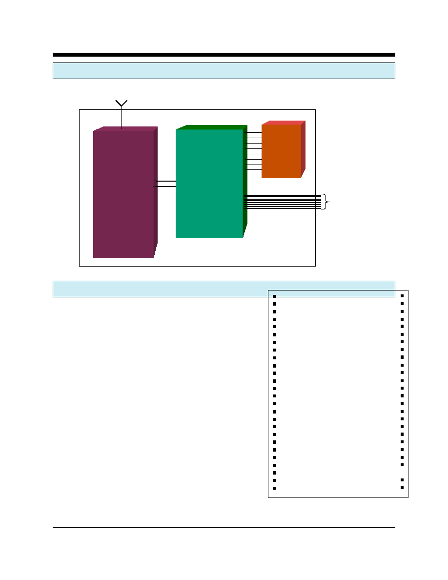
XE900M BLOCK DIAGRAM
XE900M PIN CONFIGURATION
Communications
Controller
FLASH
900 MHz
Transceiver
Antenna
TTL Level
RS232C
Inte rface
1
2
3
4
5
6
7
8
9
10
11
12
13
14
15
16
17
18
19
20
21
22
23
24
25
26
52
51
50
49
48
47
46
45
44
43
42
41
40
39
38
37
36
35
34
33
32
31
30
28
27
XE900M
RGND
RESERVED
RGND
RESERVED
RGND
RESERVED
RGND
RESERVED
RGND
RGND
I/O_1
I/O_2
I/O_3
VDD
DGND
/RST_VPP
VCC
A.D_1/Vref
/DSR(RB1)
RESERVED
RXD
RESERVED
TXD
RESERVED
/RI
RESERVED
RGND
RESERVED
RGND
RESERVED
RGND
RESERVED
RGND
RESERVED
RGND
RGND
RESERVED
I/O_0
A/D_0
RGND
/CTS
RESERVED
/DCD
RESERVED
/DTR
RESERVED
/RTS
RESERVED
RESERVED
RESERVED
RESERVED

XECOM
(4)
XE900M
XE900M PIN CONFIGURATION
SIGNAL
PINS
DESCRIPTION
RGND
1, 3, 5, 7, 9, 10, 39, 43
RGND provides the common reference point for all high frequency
44, 46,48, 50, 52
signals.
RESERVED
2, 4, 6, 8, 20, 22, 24, 26
These pins are reserved for future use. No connections should be
27, 28, 30, 31, 33, 35,
made to these pins.
37, 42, 45, 47, 49, 51
I/O_1
11
I/O_1 is a programmable I/O connected to RB5 of the XE900M's
internal micro-controller.
I/O_2
12
I/O_2 is a programmable I/O connected to RB6 of the XE900M's
internal micro-controller.
I/O_3
13
I/O_3 is a programmable I/O connected to RB7 of the XE900M's
internal micro-controller.
VDD
14
VDD provides power to the communications controller
DGND
15
DGND provides the ground reference for the modem and communica-
tions controller circuitry in the XE900M.
RST_PV
16
RST_PV provides a hardware reset line for the XE900M's communica-
tions controller.
VCC
17
VCC provides power to the 900 Mhz transceiver.
AD_1/Vref
18
Programmable I/O pin from the embedded communications controller.
Can be used as an analog input or to supply a preceision analog
reference voltage.
/DSR
19
/DSR supplies the Data Set Ready output from the XE900M. DSR is an
active low output.
RXD
21
/RXD is the serial data output from the XE900M. A Mark condition on
/RXD is active low.
TXD
23
/TXD is the serial data input to the XE900M. A Mark condition on /
RXD is active low.
/RI
25
/RI is an active low output which indicates that a wireless link has been
requested.
NO PIN
29
This pin is intentionally removed.
/RTS
32
/RTS is an active low input to the XE900M. It can be use to stop the
flow of data from the XE900M to the host. When /RTS is inactive the
XE900M will not pass data to the host.
/DTR
34
/DTR connects to the Data Terminal Ready line from the host. It is an
active low input to the XE900M.
/CTS
38
/CTS provides the Clear to Send output from the XE900M. The
XE900M deactivates /CTS to stop the flow of data from the host and
prevent a buffer overflow. This is an active low output.

XECOM
(5)
XE900M
XE900M PIN CONFIGURATION
ABSOLUTE MAXIMUM RATINGS
Storage Temperature
-25
O
C to +85
O
C
Operating Temperature Range
1
0
O
C to +70
O
C
1
Units may be screened for operation from -40 to +85C. An extra charge will be applied for this screening.
AD_0
40
Programmable I/O pin from the embedded communications controller.
Can be used as a 10-bit analog input.
I/O_0
41
I/O_0 is a programmable I/O connected to RB3 of the XE900M's
internal micro-controller.
XE900M ELECTRICAL SPECIFICATIONS
VCC
2.85
3.0
3.15
Volts
ICC
TBD
ma
Transmit Mode
VDD
2.85
3.0
3..15
Volts
IDD
TBD
ma
Transmit Mode
Output Power
-3
0
+4
dBm
50 Ohm Load
Wireless Receive Sensitivity
-94
dBm
Antenna Output
50
Ohms
RX to TX reversal
5
ms
TX to RX reversal
6
ms
Voh
2.4
Volts
Vol
0.4
Volts
Vih
2.0
VCC+0.3
Volts
Vil
-0.3
0.8
Volts
Parameter
Min
Typ
Max
Units
Comments


