 | –≠–Ľ–Ķ–ļ—ā—Ä–ĺ–Ĺ–Ĺ—č–Ļ –ļ–ĺ–ľ–Ņ–ĺ–Ĺ–Ķ–Ĺ—ā: X5043PI | –°–ļ–į—á–į—ā—Ć:  PDF PDF  ZIP ZIP |

REV 1.1.2 5/29/01
Characteristics subject to change without notice.
1 of 20
www.xicor.com
4K
X5043/X5045
512 x 8 Bit
CPU Supervisor with 4K SPI EEPROM
FEATURES
∑ Selectable time out watchdog timer
∑ Low V
CC
detection and reset assertion
--Five standard reset threshold voltages
--Re-program low V
CC
reset threshold voltage
using special programming sequence.
--Reset signal valid to V
CC
= 1V
∑ Long battery life with low power consumption
--<50ĶA max standby current, watchdog on
--<10ĶA max standby current, watchdog off
--<2mA max active current during read
∑ 2.7V to 5.5V and 4.5V to 5.5V power supply
versions
∑ 4Kbits of EEPROM≠1M write cycle endurance
∑ Save critical data with Block Lock
TM
memory
--Protect 1/4, 1/2, all or none of EEPROM array
∑ Built-in inadvertent write protection
--Write enable latch
--Write protect pin
∑ 3.3MHz clock rate
∑ Minimize programming time
--16-byte page write mode
--Self-timed write cycle
--5ms write cycle time (typical)
∑ SPI modes (0,0 & 1,1)
∑ Available packages
--8-lead MSOP, 8-lead SOIC, 8-pin PDIP
--14-lead TSSOP
DESCRIPTION
These devices combine four popular functions, Power-
on Reset Control, Watchdog Timer, Supply Voltage
Supervision, and Block Lock Protect Serial EEPROM
Memory in one package. This combination lowers
system cost, reduces board space requirements, and
increases reliability.
Applying power to the device activates the power on
reset circuit which holds RESET/RESET active for a
period of time. This allows the power supply and oscil-
lator to stabilize before the processor executes code.
The Watchdog Timer provides an independent protec-
tion mechanism for microcontrollers. When the micro-
controller fails to restart a timer within a selectable
time out interval, the device activates the RESET/
RESET signal. The user selects the interval from three
preset values. Once selected, the interval does not
change, even after cycling the power.
The device's low V
CC
detection circuitry protects the
user's system from low voltage conditions, resetting
the system when V
CC
falls below the minimum V
CC
trip point. RESET/RESET is asserted until V
CC
returns
to proper operating level and stabilizes. Five industry
standard V
TRIP
thresholds are available, however,
Xicor's unique circuits allow the threshold to be repro-
grammed to meet custom requirements or to fine-tune
the threshold for applications requiring higher precision.
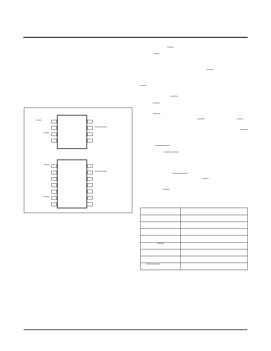
BLOCK DIAGRAM
Watchdog
Timer Reset
Data
Register
Command
Decode &
Control
Logic
SI
SO
SCK
CS/WDI
V
CC
Reset &
Watchdog
Timebase
Power on and
Generation
V
TRIP
+
-
RESET/RESET
Reset
Low Voltage
Status
Register
Protect Logic
1Kbits
1Kbits
2Kbits
EEPROM Array
Watchdog Transition
Detector
WP
X5043 = RESET
X5045 = RESET
V
CC
Threshold
Reset Logic
X5043/X5045
Characteristics subject to change without notice.
2 of 20
REV 1.1.2 5/29/01
www.xicor.com
The memory portion of the device is a CMOS Serial
EEPROM array with Xicor's block lock protection. The
array is internally organized as x 8. The device features
a Serial Peripheral Interface (SPI) and software proto-
col allowing operation on a simple four-wire bus.
The device utilizes Xicor's proprietary Direct Write
TM
cell, providing a minimum endurance of 1,000,000
cycles and a minimum data retention of 100 years.
PIN CONFIGURATION
PIN DESCRIPTIONS
Serial Output (SO)
SO is a push/pull serial data output pin. During a read
cycle, data is shifted out on this pin. Data is clocked out
by the falling edge of the serial clock.
Serial Input (SI)
SI is the serial data input pin. All opcodes, byte
addresses, and data to be written to the memory are
input on this pin. Data is latched by the rising edge of
the serial clock.
Serial Clock (SCK)
The Serial Clock controls the serial bus timing for data
input and output. Opcodes, addresses, or data present
on the SI pin is latched on the rising edge of the clock
input, while data on the SO pin changes after the fall-
ing edge of the clock input.
Chip Select (CS)
When CS is high, the X5043/45 is deselected and the
SO output pin is at high impedance and, unless an
internal write operation is underway, the X5043/45 will
be in the standby power mode. CS low enables the
X5043/45, placing it in the active power mode. It should
be noted that after power-up, a high to low transition on
CS is required prior to the start of any operation.
Write Protect (WP)
When WP is low, nonvolatile writes to the X5043/45 are
disabled, but the part otherwise functions normally.
When WP is held high, all functions, including non vol-
atile writes operate normally. WP going low while CS is
still low will interrupt a write to the X5043/45. If the
internal write cycle has already been initiated, WP
going low will have no affect on a write.
Reset (RESET, RESET)
X5043/45, RESET/RESET is an active low/HIGH,
open drain output which goes active whenever V
CC
falls below the minimum V
CC
sense level. It will remain
active until V
CC
rises above the minimum V
CC
sense
level for 200ms. RESET/RESET also goes active if the
Watchdog timer is enabled and CS remains either high
or low longer than the Watchdog time out period. A fall-
ing edge of CS will reset the watchdog timer.
PIN NAMES
8-Lead SOIC/PDIP/MSOP
CS/WDI
WP
SO
1
2
3
4
RESET/RESET
8
7
6
5
V
CC
X5043/45
V
SS
SCK
SI
14-Lead TSSOP
CS
NC
SO
1
2
3
4
RESET/RESET
14
13
12
11
V
CC
X5043/45
NC
NC
NC
WP
NC
5
6
7
V
SS
NC
10
9
8
SCK
SI
Symbol
Description
CS
Chip Select Input
SO
Serial Output
SI
Serial Input
SCK
Serial Clock Input
WP
Write Protect Input
V
SS
Ground
V
CC
Supply Voltage
RESET/RESET
Reset Output
X5043/X5045
Characteristics subject to change without notice.
3 of 20
REV 1.1.2 5/29/01
www.xicor.com
PRINCIPLES OF OPERATION
Power On Reset
Application of power to the X5043/X5045 activates a
Power On Reset Circuit. This circuit pulls the RESET/
RESET pin active. RESET/RESET prevents the sys-
tem microprocessor from starting to operate with insuf-
ficient voltage or prior to stabilization of the oscillator.
When V
CC
exceeds the device V
TRIP
value for 200ms
(nominal) the circuit releases RESET/RESET, allowing
the processor to begin executing code.
Low Voltage Monitoring
During operation, the X5043/X5045 monitors the V
CC
level and asserts RESET/RESET if supply voltage falls
below a preset minimum V
TRIP
. The RESET/RESET
signal prevents the microprocessor from operating in a
power fail or brownout condition. The RESET/RESET
signal remains active until the voltage drops below 1V.
It also remains active until V
CC
returns and exceeds
V
TRIP
for 200ms.
Watchdog Timer
The Watchdog Timer circuit monitors the microproces-
sor activity by monitoring the WDI input. The micropro-
cessor must toggle the CS/WDI pin periodically to
prevent an active RESET/RESET signal. The CS/WDI
pin must be toggled from HIGH to LOW prior to the
expiration of the watchdog time out period. The state of
two nonvolatile control bits in the Status Register
determines the watchdog timer period. The micropro-
cessor can change these watchdog bits. With no
microprocessor action, the watchdog timer control bits
remain unchanged, even during total power failure.
V
CC
Threshold Reset Procedure
The X5043/X5045 is shipped with a standard V
CC
threshold (V
TRIP
) voltage. This value will not change
over normal operating and storage conditions. How-
ever, in applications where the standard V
TRIP
is not
exactly right, or if higher precision is needed in the
V
TRIP
value, the X5043/X5045 threshold may be
adjusted. The procedure is described below, and uses
the application of a high voltage control signal.
Setting the V
TRIP
Voltage
This procedure is used to set the V
TRIP
to a higher volt-
age value. For example, if the current V
TRIP
is 4.4V
and the new V
TRIP
is 4.6V, this procedure will directly
make the change. If the new setting is to be lower than
the current setting, then it is necessary to reset the trip
point before setting the new value.
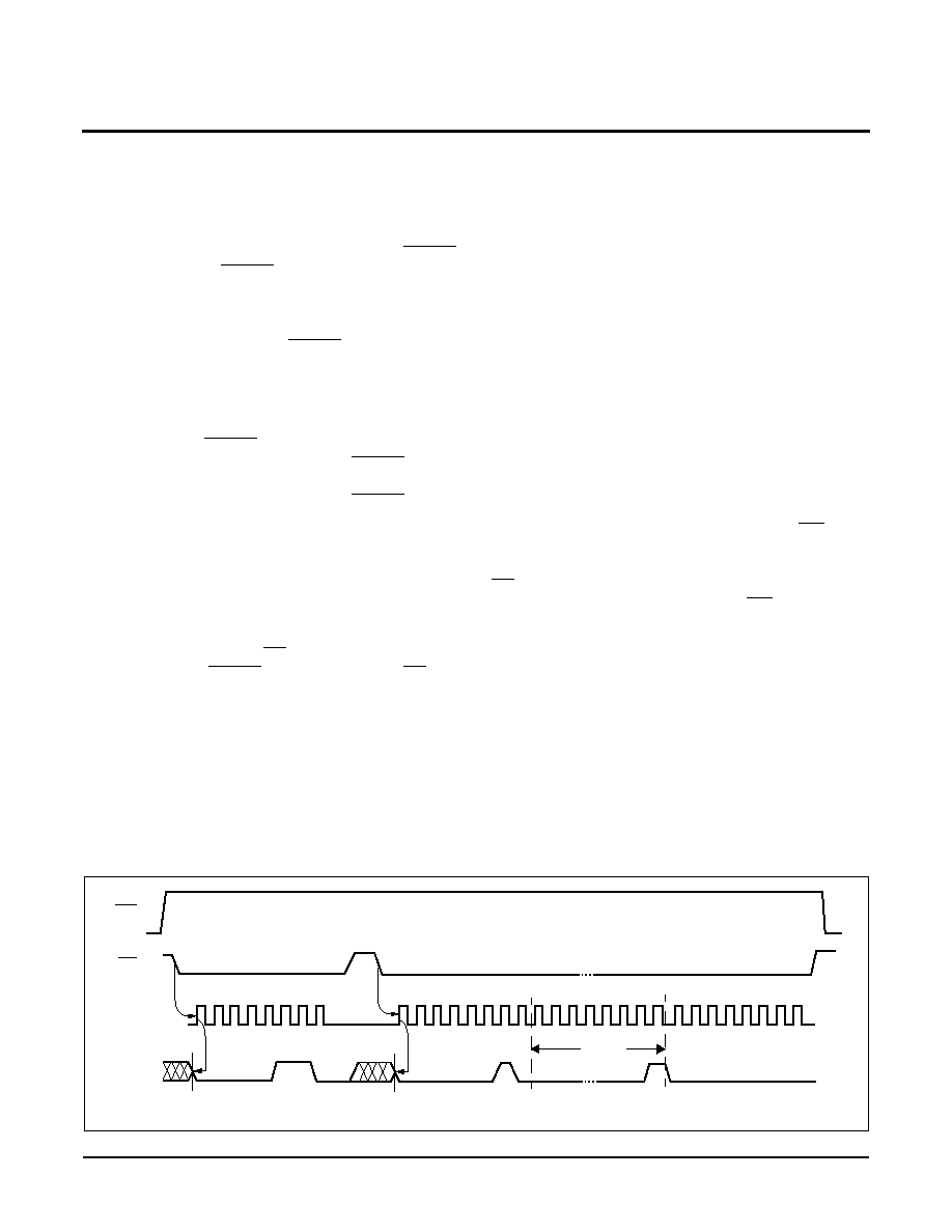
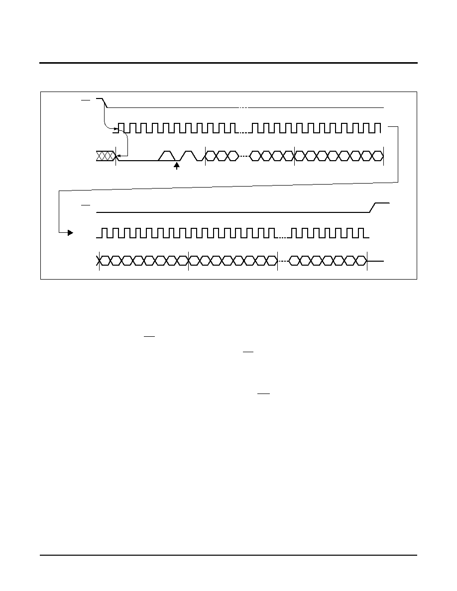
To set the new V
TRIP
voltage, apply the desired V
TRIP
threshold voltage to the V
CC
pin and tie the WP pin to
the programming voltage V
P
. Then send a WREN com-
mand, followed by a write of Data 00h to address 01h.
CS going HIGH on the write operation initiates the
V
TRIP
programming sequence. Bring WP LOW to com-
plete the operation.
Note:
This operation also writes 00h to array address 01h.
Figure 1. Set V
TRIP
Level Sequence (V
CC
= desired V
TRIP
value.)
0 1 2 3 4 5 6 7
SCK
SI
CS
06h
0 1 2 3 4 5 6 7 8 9 10
12 13 14 15
8 Bits
01h
02h
WP
V
PE
= 15-18V
00h
WREN
Write
Address
Data
11

X5043/X5045
Characteristics subject to change without notice.
4 of 20
REV 1.1.2 5/29/01
www.xicor.com
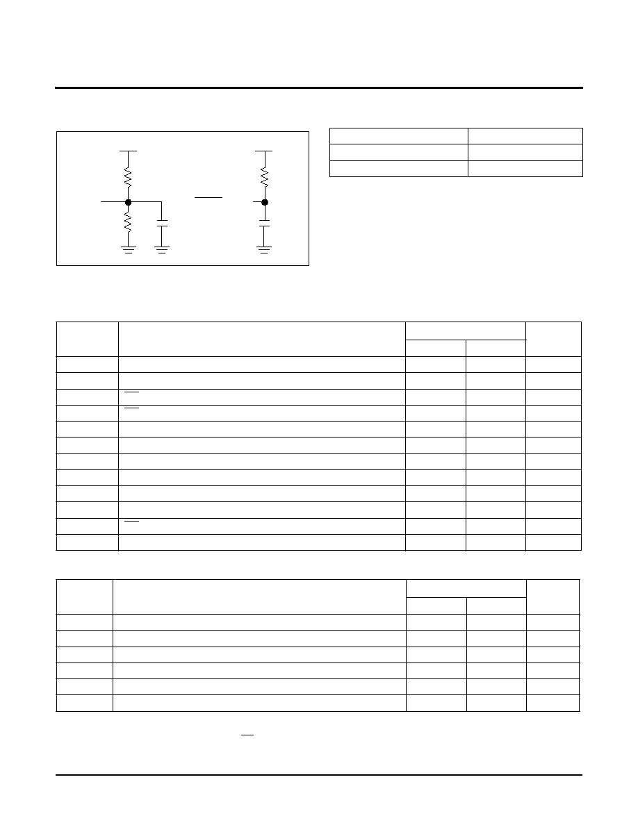
Resetting the V
TRIP
Voltage
This procedure is used to set the V
TRIP
to a "native"
voltage level. For example, if the current V
TRIP
is 4.4V
and the new V
TRIP
must be 4.0V, then the V
TRIP
must
be reset. When V
TRIP
is reset, the new V
TRIP
is some-
thing less than 1.7V. This procedure must be used to
set the voltage to a lower value.
To reset the V
TRIP
voltage, apply at least 3V to the V
CC
pin and tie the WP pin to the programming voltage V
P
.
Then send a WREN command, followed by a write of
Data 00h to address 03h. CS going HIGH on the write
operation initiates the V
TRIP
programming sequence.
Bring WP LOW to complete the operation.
Note:
This operation also writes 00h to array address
03h.
Figure 2. Reset V
TRIP
Level Sequence (V
CC
> 3V. WP = 15≠18V)
Figure 3. Sample V
TRIP
Reset Circuit
0 1 2 3 4 5 6 7
SCK
SI
CS
06h
0 1 2 3 4 5 6 7 8 9 10
12 13 14 15
8 Bits
03h
02h
WP
V
PE
= 15-18V
00h
WREN
Write
Address
Data
11
1
2
3
4
8
7
6
5
X5043
V
TRIP
Adj.
V
P
RESET
4.7K
SI
SO
CS
SCK
ĶC
Adjust
Run
X5045

X5043/X5045
Characteristics subject to change without notice.
5 of 20
REV 1.1.2 5/29/01
www.xicor.com
Figure 4. V
TRIP
Programming Sequence
SPI Serial Memory
The memory portion of the device is a CMOS Serial
EEPROM array with Xicor's block lock
protection. The
array is internally organized as x8 bits. The device fea-
tures a Serial Peripheral Interface (SPI) and software
protocol allowing operation on a simple four-wire bus.
The device utilizes Xicor's proprietary Direct Write
TM
cell, providing a minimum endurance of 1,000,000
cycles and a minimum data retention of 100 years.
The device is designed to interface directly with the
synchronous Serial Peripheral Interface (SPI) of many
popular microcontroller families.
The device contains an 8-bit instruction register that
controls the operation of the device. The instruction
code is written to the device via the SI input. There are
two write operations that requires only the instruction
byte. There are two read operations that use the
instruction byte to initiate the output of data. The
remainder of the operations require an instruction byte,
an 8-bit address, then data bytes. All instruction,
address and data bits are clocked by the SCK input. All
instructions (Table 1), addresses and data are trans-
ferred MSB first.
Clock and Data Timing
Data input on the SI line is latched on the first rising
edge of SCK after CS goes LOW. Data is output on the
SO line by the falling edge of SCK. SCK is static,
allowing the user to stop the clock and then start it
again to resume operations where left off. CS must be
LOW during the entire operation.
V
TRIP
Programming
Apply 5V to V
CC
Decrement V
CC
RESET pin
goes active?
Measured V
TRIP
-Desired V
TRIP
DONE
Execute
Sequence
Reset V
TRIP
Set V
CC
= V
CC
Applied =
Desired V
TRIP
Execute
Sequence
Set V
TRIP
New V
CC
Applied
Old V
CC
Applied
(V
CC
= V
CC
≠10mV)
Execute
Sequence
Reset V
TRIP
Error
-Emax
-Emax < Error < Emax
YES
NO
Error
Emax
Emax = Maximum Desired Error
- Error
=
New V
CC
Applied
Old V
CC
Applied
- Error
=
Table 1. Instruction Set
Note:
*Instructions are shown MSB in leftmost position. Instructions are transferred MSB first.
Instruction Name
Instruction Format*
Operation
WREN
0000 0110
Set the Write Enable Latch (Enable Write Operations)
WRDI
0000 0100
Reset the Write Enable Latch (Disable Write Operations)
RSDR
0000 0101
Read Status Register
WRSR
0000 0001
Write Status Register (Watchdog and Block Lock)
READ
0000 A
8
011
Read Data from Memory Array Beginning at Selected Address
WRITE
0000 A
8
010
Write Data to Memory Array Beginning at Selected Address (1 to 16 bytes)
X5043/X5045
Characteristics subject to change without notice.
6 of 20
REV 1.1.2 5/29/01
www.xicor.com
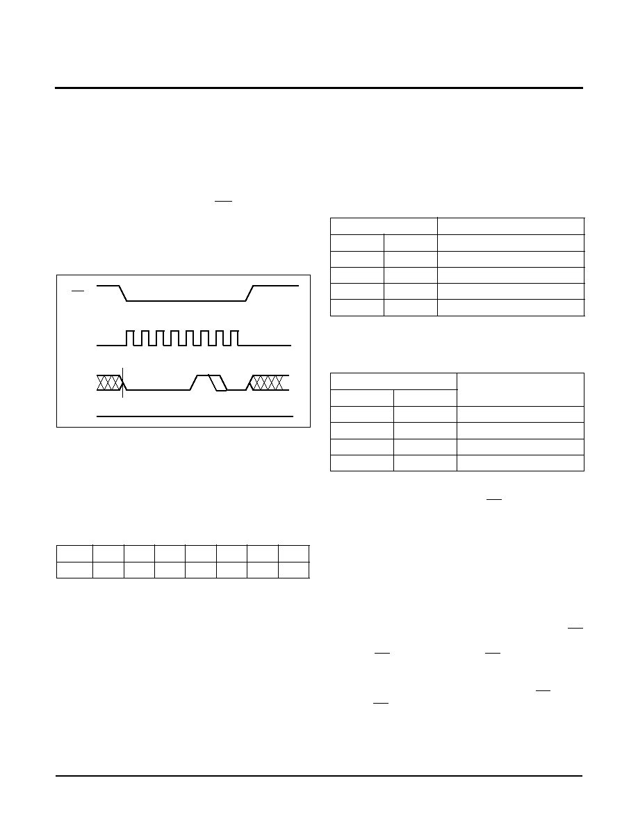
Write Enable Latch
The device contains a Write Enable Latch. This latch
must be SET before a Write Operation is initiated. The
WREN instruction will set the latch and the WRDI
instruction will reset the latch (Figure 3). This latch is
automatically reset upon a power-up condition and after
the completion of a valid byte, page, or status register
write cycle. The latch is also reset if WP is brought LOW.
When issuing a WREN, WRDI or RDSR commands, it
is not necessary to send a byte address or data.
Figure 5. Write Enable/Disable Latch Sequence
Status Register
The Status Register contains four nonvolatile control
bits and two volatile status bits. The control bits set the
operation of the watchdog timer and the memory block
lock protection. The Status Register is formatted as
shown in "Status Register".
Status Register: (Default = 30H)
The Write-In-Progress (WIP) bit is a volatile, read only
bit and indicates whether the device is busy with an
internal nonvolatile write operation. The WIP bit is read
using the RDSR instruction. When set to a "1", a non-
volatile write operation is in progress. When set to a
"0", no write is in progress.
The Write Enable Latch (WEL) bit indicates the status
of the "write enable" latch. When WEL = 1, the latch is
set and when WEL = 0 the latch is reset. The WEL bit is
a volatile, read only bit. The WREN instruction sets the
WEL bit and the WRDS instruction resets the WEL bit.
The block lock bits, BL0 and BL1, set the level of block
lock
protection. These nonvolatile bits are programmed
using the WRSR instruction and allow the user to pro-
tect one quarter, one half, all or none of the EEPROM
array. Any portion of the array that is block lock pro-
tected can be read but not written. It will remain pro-
tected until the BL bits are altered to disable block lock
protection of that portion of memory.
The Watchdog Timer bits, WD0 and WD1, select the
Watchdog Time-out Period. These nonvolatile bits are
programmed with the WRSR instruction.
Read Status Register
To read the Status Register, pull CS low to select the
device, then send the 8-bit RDSR instruction. Then the
contents of the Status Register are shifted out on the
SO line, clocked by CLK. Refer to the Read Status
Register Sequence (Figure 6). The Status Register
may be read at any time, even during a Write Cycle.
Write Status Register
Prior to any attempt to write data into the status regis-
ter, the "Write Enable" Latch (WEL) must be set by
issuing the WREN instruction (Figure 5). First pull CS
LOW, then clock the WREN instruction into the device
and pull CS HIGH. Then bring CS LOW again and
enter the WRSR instruction followed by 8 bits of data.
These 8 bits of data correspond to the contents of the
status register. The operation ends with CS going
HIGH. If CS does not go HIGH between WREN and
WRSR, the WRSR instruction is ignored.
7
6
5
4
3
2
1
0
0
0
WD1 WD0
BL1
BL0
WEL
WIP
0
1
2
3
4
5
6
7
CS
SI
SCK
High Impedance
SO
Status Reg Bits
Array Addresses Protected
BL1
BL0
X5043/X5045
0
0
None
0
1
$180≠$1FF
1
0
$100≠$1FF
1
1
$000≠$1FF
Status Register Bits
Watchdog Time Out
(Typical)
WD1
WD0
0
0
1.4 seconds
0
1
600 milliseconds
1
0
200 milliseconds
1
1
disabled (factory default)
X5043/X5045
Characteristics subject to change without notice.
7 of 20
REV 1.1.2 5/29/01
www.xicor.com
Table 2. Device Protect Matrix
Figure 6. Read Status Register Sequence
Figure 7. Write Status Register Sequence
WREN CMD
(WEL)
Device Pin
(WP)
Memory Block
Status Register
Protected Area
Unprotected Area
(BL0, BL1, WD0, WD1)
0
x
Protected
Protected
Protected
x
0
Protected
Protected
Protected
1
1
Protected
Writable
Writable
0
1
2
3
4
5
6
7
8
9 10 11 12 13 14
7
6
5
4
3
2
1
0
Data Out
CS
SCK
SI
SO
MSB
High Impedance
Instruction
15
0
1
2
3
4
5
6
7
8
9
CS
SCK
SI
SO
High Impedance
Instruction
Data Byte
7
6
5
4
3
2
1
0
10 11 12 13 14 15
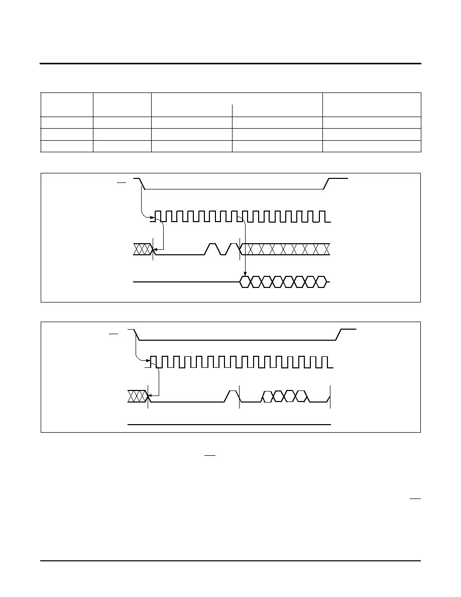
Read Memory Array
When reading from the EEPROM memory array, CS is
first pulled low to select the device. The 8-bit READ
instruction is transmitted to the device, followed by the
8-bit address. Bit 3 of the READ instruction selects the
upper or lower half of the device. After the READ
opcode and address are sent, the data stored in the
memory at the selected address is shifted out on the
SO line. The data stored in memory at the next
address can be read sequentially by continuing to pro-
vide clock pulses. The address is automatically incre-
mented to the next higher address after each byte of
data is shifted out. When the highest address is
reached, the address counter rolls over to address
$000 allowing the read cycle to be continued indefi-
nitely. The read operation is terminated by taking CS
high. Refer to the Read EEPROM Array Sequence
(Figure 8).

X5043/X5045
Characteristics subject to change without notice.
8 of 20
REV 1.1.2 5/29/01
www.xicor.com
Figure 8. Read EEPROM Array Sequence
0
1
2
3
4
5
6
7
8
9
10
12 13 14 15
16 17
18 19 20 21 22
7
6
5
4
3
2
1
0
Data Out
CS
SCK
SI
SO
MSB
High Impedance
Instruction
8 Bit Address
7
6
5
3
2
1
0
8
9
th
Bit of Address
Write Memory Array
Prior to any attempt to write data into the memory
array, the "Write Enable" Latch (WEL) must be set by
issuing the WREN instruction (Figure 5). First pull CS
LOW, then clock the WREN instruction into the device
and pull CS HIGH. Then bring CS LOW again and
enter the WRITE instruction followed by the 8-bit
address and then the data to be written. Bit 3 of the
WRITE instruction contains address bit A
8
, which
selects the upper or lower half of the array. If CS does
not go HIGH between WREN and WRITE, the WRITE
instruction is ignored.
The WRITE operation requires at least 16 clocks. CS
must go low and remain low for the duration of the
operation. The host may continue to write up to 16
bytes of data. The only restriction is that the 16 bytes
must reside within the same page. A page address
begins with address [x xxxx 0000] and ends with [x
xxxx 1111]. If the byte address reaches the last byte on
the page and the clock continues, the counter will roll
back to the first address of the page and overwrite any
data that has been previously written.
For the write operation (byte or page write) to be com-
pleted, CS must be brought HIGH after bit 0 of the last
complete data byte to be written is clocked in. If it is
brought HIGH at any other time, the write operation will
not be completed (Figure 9).
While the write is in progress following a status register
or memory array write sequence, the Status Register
may be read to check the WIP bit. WIP is HIGH while
the nonvolatile write is in progress.
X5043/X5045
Characteristics subject to change without notice.
9 of 20
REV 1.1.2 5/29/01
www.xicor.com
Figure 9. Write Memory Sequence
24 25 26 27 28 29 30 31
SCK
SI
CS
0
1
2
3
4
5
6
7
8
9
10
SCK
SI
Instruction
8 Bit Address
Data Byte 1
7
6
5
4
3
2
1
0
CS
32 33 34 35 36 37 38 39
Data Byte 2
7
6
5
4
3
2
1
0
Data Byte 3
7
6
5
4
3
2
1
0
Data Byte N
7
6
5
3
2
1
0
12 13 14 15 16 17 18 19 20 21 22 23
6
5
4
3
2
1
0
9
th
Bit of Address
8
OPERATIONAL NOTES
The device powers-up in the following state:
≠ The device is in the low power standby state.
≠ A HIGH to LOW transition on CS is required to enter
an active state and receive an instruction.
≠ SO pin is high impedance.
≠ The Write Enable Latch is reset.
≠ The Flag Bit is reset.
≠ Reset Signal is active for t
PURST
.
Data Protection
The following circuitry has been included to prevent
inadvertent writes:
≠ A WREN instruction must be issued to set the Write
Enable Latch.
≠ CS must come HIGH at the proper clock count in
order to start a nonvolatile write cycle.
≠ Block Protect bits provide additional level of write
protection for the memory array.
≠ The WP pin LOW blocks nonvolatile write operations.

X5043/X5045
Characteristics subject to change without notice.
10 of 20
REV 1.1.2 5/29/01
www.xicor.com
ABSOLUTE MAXIMUM RATINGS
Temperature under bias ....................≠65įC to +135įC
Storage temperature ........................≠65įC to +150įC
Voltage on any pin with
respect to V
SS
...................................... ≠1.0V to +7V
D.C. output current ............................................... 5mA
Lead temperature (soldering, 10 seconds).........300įC
COMMENT
Stresses above those listed under "Absolute Maximum
Ratings" may cause permanent damage to the device.
This is a stress rating only; functional operation of the
device (at these or any other conditions above those
listed in the operational sections of this specification) is
not implied. Exposure to absolute maximum rating con-
ditions for extended periods may affect device reliability.
RECOMMENDED OPERATING CONDITIONS
Temperature
Min.
Max.
Commercial
0įC
70įC
Industrial
≠40įC
+85įC
Option
Supply Voltage Limits
-2.7, -2.7A
2.7V to 5.5V
Blank, -4.5A
4.5V to 5.5V
D.C. OPERATING CHARACTERISTICS (Over the recommended operating conditions unless otherwise specified.)
CAPACITANCE T
A
= +25įC, f = 1MHz, V
CC
= 5V
Notes: (1) V
IL
min. and V
IH
max. are for reference only and are not tested.
(2) This parameter is periodically sampled and not 100% tested.
(3) SCK frequency measured from V
CC
x 0.1/V
CC
x 0.9
Symbol
Parameter
Limits
Unit
Test Conditions/Comments
Min.
Typ.
(2)
Max.
I
CC1
V
CC
Write Current (Active)
3
mA
SCK = 3.3MHz
(3)
; SO, RESET,
RESET = Open
I
CC2
V
CC
Read Current (Active)
2
mA
SCK = 3.3MHz
(3)
; SI = V
SS
, RESET,
RESET = Open
I
SB1
V
CC
Standby Current
WDT = OFF
10
ĶA
CS = V
CC
, SCK, SI = V
SS
,
V
CC
= 5.5V
I
SB2
V
CC
Standby Current
WDT = ON
50
ĶA
CS = V
CC
, SCK, SI = V
SS
,
V
CC
= 5.5V
I
LI
Input Leakage Current
0.1
10
ĶA
SCK, SI, WP = V
SS
to V
CC
I
LO
Output Leakage Current
0.1
10
ĶA
SO, RESET, RESET = V
SS
to V
CC
V
IL
(1)
Input LOW Voltage
≠0.5
V
CC
x 0.3
V
SCK, SI, WP, CS
V
IH
(1)
Input HIGH Voltage
V
CC
x 0.7
V
CC
+ 0.5
V
SCK, SI, WP, CS
V
OL
Output LOW Voltage (SO)
0.4
V
I
OL
= 2mA @ V
CC
= 2.7V
I
OL
= 0.5mA @ V
CC
= 1.8V
V
OH1
Output HIGH Voltage (SO)
V
CC
≠ 0.8
V
V
CC
> 3.3V, I
OH
= ≠1.0mA
V
OH2
Output HIGH Voltage (SO)
V
CC
≠ 0.4
V
2V < V
CC
3.3V, I
OH
= ≠0.4mA
V
OH3
Output HIGH Voltage (SO)
V
CC
≠ 0.2
V
V
CC
2V, I
OH
= ≠0.25mA
V
OLRS
Output LOW Voltage
(RESET, RESET)
0.4
V
I
OL
= 1mA
Symbol
Test
Max.
Unit
Conditions
C
OUT
(2)
Output Capacitance (SO, RESET, RESET)
8
pF
V
OUT
= 0V
C
IN
(2)
Input Capacitance (SCK, SI, CS, WP)
6
pF
V
IN
= 0V
X5043/X5045
Characteristics subject to change without notice.
11 of 20
REV 1.1.2 5/29/01
www.xicor.com
Equivalent A.C. Load Circuit at 5V V
CC
A.C. Test Conditions
5V
Output
30pF
5V
4.6K
RESET/RESET
30pF
1.64K
1.64K
Input pulse levels
V
CC
x 0.1 to V
CC
x 0.9
Input rise and fall times
10ns
Input and output timing level
V
CC
x0.5
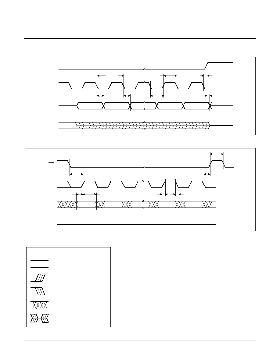
A.C. CHARACTERISTICS (Over recommended operating conditions, unless otherwise specified)
Data Input Timing
Data Output Timing
Notes: (3) This parameter is periodically sampled and not 100% tested.
(4) t
WC
is the time from the rising edge of CS after a valid write sequence has been sent to the end of the self-timed internal nonvolatile
write cycle.
Symbol
Parameter
2.7V≠5.5V
Unit
Min.
Max.
f
SCK
Clock Frequency
0
3.3
MHz
t
CYC
Cycle Time
300
ns
t
LEAD
CS Lead Time
150
ns
t
LAG
CS Lag Time
150
ns
t
WH
Clock HIGH Time
130
ns
t
WL
Clock LOW Time
130
ns
t
SU
Data Setup Time
30
ns
t
H
Data Hold Time
30
ns
t
RI
(3)
Input Rise Time
2
Ķs
t
FI
(3)
Input Fall Time
2
Ķs
t
CS
CS Deselect Time
100
ns
t
WC
(4)
Write Cycle Time
10
ms
Symbol Parameter
2.7≠5.5V
Unit
Min.
Max.
f
SCK
Clock Frequency
0
3.3
MHz
t
DIS
Output Disable Time
150
ns
t
V
Output Valid from Clock Low
120
ns
t
HO
Output Hold Time
0
ns
t
RO
(3)
Output Rise Time
50
ns
t
FO
(3)
Output Fall Time
50
ns
X5043/X5045
Characteristics subject to change without notice.
12 of 20
REV 1.1.2 5/29/01
www.xicor.com
Serial Output Timing
Serial Input Timing
SYMBOL TABLE
SCK
CS
SO
SI
MSB Out
MSB≠1 Out
LSB Out
ADDR
LSB IN
t
CYC
t
V
t
HO
t
WL
t
WH
t
DIS
t
LAG
SCK
CS
SI
SO
MSB In
t
SU
t
RI
t
LAG
t
LEAD
t
H
LSB In
t
CS
tFI
High Impedance
WAVEFORM
INPUTS
OUTPUTS
Must be
steady
Will be
steady
May change
from LOW
to HIGH
Will change
from LOW
to HIGH
May change
from HIGH
to LOW
Will change
from HIGH
to LOW
Don't Care:
Changes
Allowed
Changing:
State Not
Known
N/A
Center Line
is High
Impedance
X5043/X5045
Characteristics subject to change without notice.
13 of 20
REV 1.1.2 5/29/01
www.xicor.com
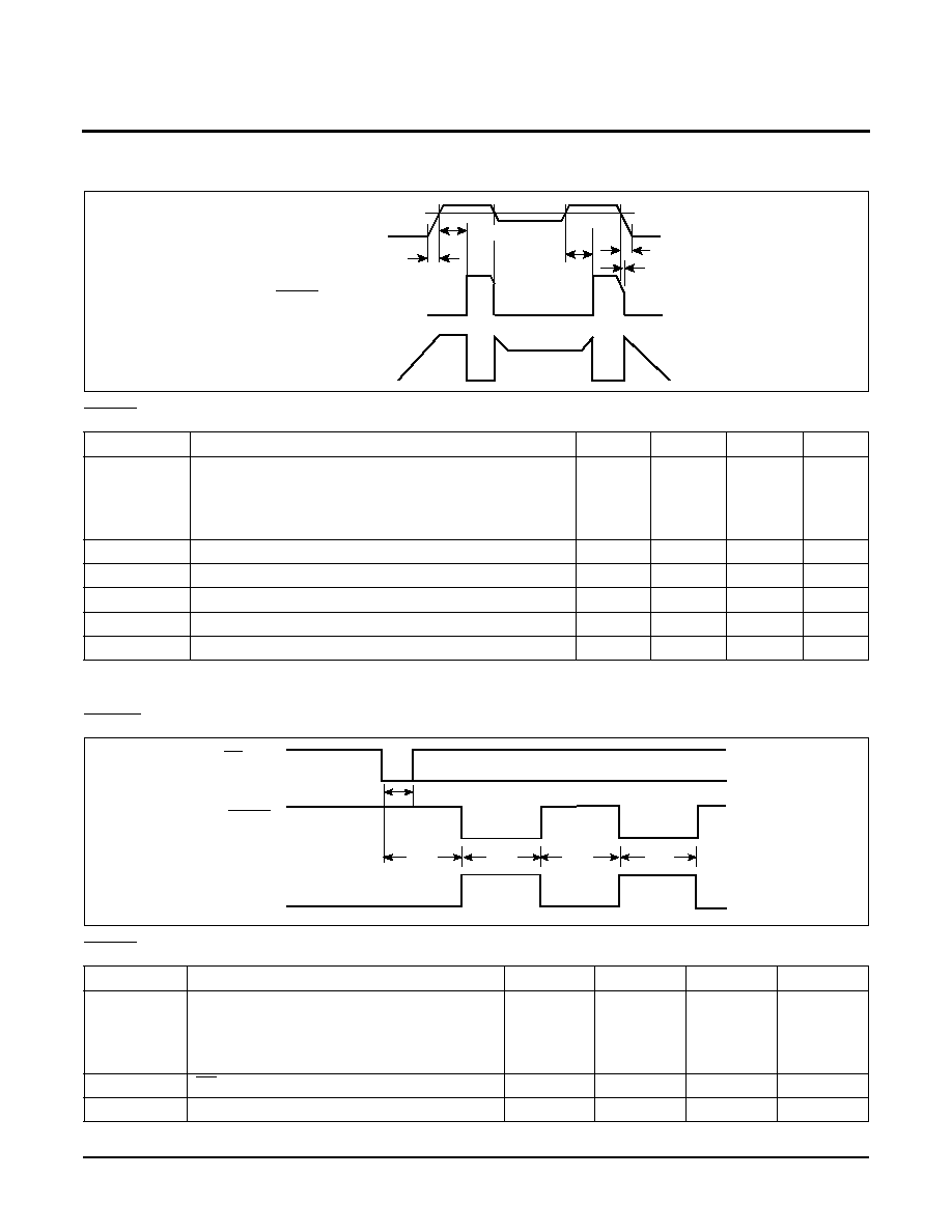
Power-Up and Power-Down Timing
RESET Output Timing
Note:
(5) This parameter is periodically sampled and not 100% tested.
CS/WDI vs. RESET/RESET Timing
RESET/RESET Output Timing
Symbol
Parameter
Min.
Typ.
Max.
Unit
V
TRIP
Reset Trip Point Voltage, (-4.5A)
Reset Trip Point Voltage, (Blank)
Reset Trip Point Voltage, (-2.7A)
Reset Trip Point Voltage, (-2.7)
4.5
4.25
2.85
2.55
4.62
4.38
2.92
2.62
4.75
4.5
3.0
2.7
V
t
PURST
Power-up Reset Time Out
100
200
400
ms
t
RPD
(5)
V
CC
Detect to Reset/Output
500
ns
t
F
(5)
V
CC
Fall Time
10
Ķs
t
R
(5)
V
CC
Rise Time
0.1
ns
V
RVALID
Reset Valid V
CC
1
V
Symbol
Parameter
Min.
Typ.
Max.
Unit
t
WDO
Watchdog Time Out Period,
WD1 = 1, WD0 = 0
WD1 = 0, WD0 = 1
WD1 = 0, WD0 = 0
100
450
1
200
600
1.4
300
800
2
ms
ms
sec
t
CST
CS Pulse Width to Reset the Watchdog
400
ns
t
RST
Reset Time Out
100
200
400
ms
V
CC
t
PURST
t
F
t
RPD
RESET (X5043)
0 Volts
V
TRIP
RESET (X5045)
V
TRIP
t
PURST
t
R
CS/WDI
t
CST
RESET
RESET
t
WDO
t
RST
t
WDO
t
RST

X5043/X5045
Characteristics subject to change without notice.
14 of 20
REV 1.1.2 5/29/01
www.xicor.com
V
TRIP
Programming Timing Diagram
V
TRIP
Programming Parameters
Parameter
Description
Min
Max
Unit
t
VPS
V
TRIP
Program Enable Voltage Setup time
1
Ķs
t
VPH
V
TRIP
Program Enable Voltage Hold time
1
Ķs
t
PCS
V
TRIP
Programming CS inactive time
1
Ķs
t
TSU
V
TRIP
Setup time
1
Ķs
t
THD
V
TRIP
Hold (stable) time
10
ms
t
WC
V
TRIP
Write Cycle Time
10
ms
t
VPO
V
TRIP
Program Enable Voltage Off time (Between successive adjustments)
0
Ķs
t
RP
V
TRIP
Program Recovery Period (Between successive adjustments)
10
ms
V
P
Programming Voltage
15
18
V
V
TRAN
V
TRIP
Programmed Voltage Range
1.7
5.0
V
V
ta1
Initial V
TRIP
Program Voltage accuracy (V
CC
applied≠V
TRIP
) (Programmed
at 25įC.)
-0.1
+0.4
V
V
ta2
Subsequent V
TRIP
Program Voltage accuracy [(V
CC
applied≠V
ta1
)≠V
TRIP
.
Programmed at 25įC.)
-25
+25
mV
V
tr
V
TRIP
Program Voltage repeatability (Successive program operations.
Programmed at 25įC.)
-25
+25
mV
V
tv
V
TRIP
Program variation after programming (0≠75įC). (Programmed at 25įC.)
-25
+25
mV
V
TRIP programming parameters are periodically sampled and are not 100% tested.
SCK
SI
CS
01h or
V
CC
(V
TRIP
)
WP
t
TSU
t
THD
t
VPH
t
VPS
V
P
V
TRIP
t
RP
t
VPO
t
PCS
02h
06h
03h
X5043/X5045
Characteristics subject to change without notice.
15 of 20
REV 1.1.2 5/29/01
www.xicor.com
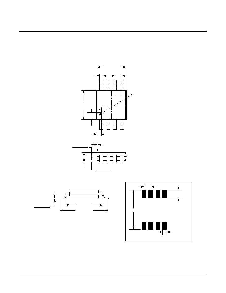
PACKAGING INFORMATION
0.118 Ī 0.002
(3.00 Ī 0.05)
0.040 Ī 0.002
(1.02 Ī 0.05)
0.150 (3.81)
Ref.
0.193 (4.90)
0.030 (0.76)
0.036 (0.91)
0.032 (0.81)
0.007 (0.18)
0.005 (0.13)
0.008 (0.20)
0.004 (0.10)
0.0216 (0.55)
7į Typ.
R 0.014 (0.36)
0.118 Ī 0.002
(3.00 Ī 0.05)
0.012 + 0.006 / -0.002
(0.30 + 0.15 / -0.05)
0.0256 (0.65) Typ.
8-Lead Miniature Small Outline Gull Wing Package Type M
NOTE:
1. ALL DIMENSIONS IN INCHES AND (MILLIMETERS)
0.220"
0.0256" Typical
0.025"
Typical
0.020"
Typical
8 Places
FOOTPRINT
Ref.
X5043/X5045
Characteristics subject to change without notice.
16 of 20
REV 1.1.2 5/29/01
www.xicor.com
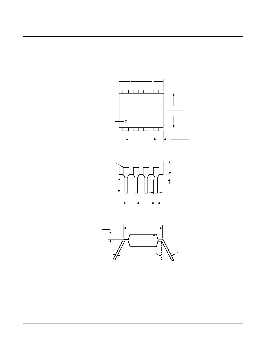
PACKAGING INFORMATION
NOTE:
1. ALL DIMENSIONS IN INCHES (IN PARENTHESES IN MILLIMETERS)
2. PACKAGE DIMENSIONS EXCLUDE MOLDING FLASH
0.020 (0.51)
0.016 (0.41)
0.150 (3.81)
0.125 (3.18)
0.110 (2.79)
0.090 (2.29)
0.430 (10.92)
0.360 (9.14)
0.300
(7.62) Ref.
Pin 1 Index
0.145 (3.68)
0.128 (3.25)
0.025 (0.64)
0.015 (0.38)
Pin 1
Seating
0.065 (1.65)
0.045 (1.14)
0.260 (6.60)
0.240 (6.10)
0.060 (1.52)
0.020 (0.51)
Typ. 0.010 (0.25)
0į
15į
8-Lead Plastic Dual In-Line Package Type P
Half Shoulder Width On
All End Pins Optional
.073 (1.84)
Max.
0.325 (8.25)
0.300 (7.62)
Plane
X5043/X5045
Characteristics subject to change without notice.
17 of 20
REV 1.1.2 5/29/01
www.xicor.com
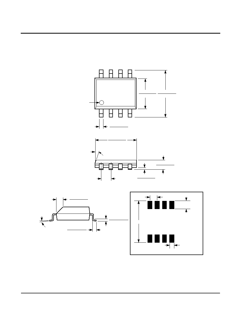
PACKAGING INFORMATION
0.150 (3.80)
0.158 (4.00)
0.228 (5.80)
0.244 (6.20)
0.014 (0.35)
0.019 (0.49)
Pin 1
Pin 1 Index
0.010 (0.25)
0.020 (0.50)
0.050 (1.27)
0.188 (4.78)
0.197 (5.00)
0.004 (0.19)
0.010 (0.25)
0.053 (1.35)
0.069 (1.75)
(4X) 7į
0.016 (0.410)
0.037 (0.937)
0.0075 (0.19)
0.010 (0.25)
0į - 8į
X 45į
8-Lead Plastic Small Outline Gull Wing Package Type S
NOTE: ALL DIMENSIONS IN INCHES (IN PARENTHESES IN MILLIMETERS)
0.250"
0.050"Typical
0.050"
Typical
0.030"
Typical
8 Places
FOOTPRINT
X5043/X5045
Characteristics subject to change without notice.
18 of 20
REV 1.1.2 5/29/01
www.xicor.com
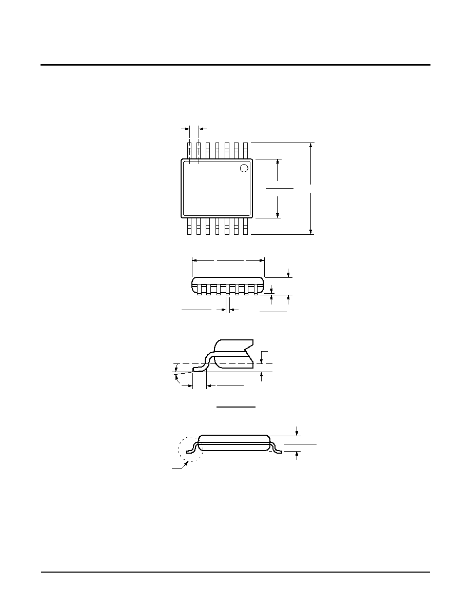
PACKAGING INFORMATION
NOTE: ALL DIMENSIONS IN INCHES (IN PARENTHESES IN MILLIMETERS)
14-Lead Plastic, TSSOP, Package Type V
See Detail "A"
.031 (.80)
.041 (1.05)
.169 (4.3)
.177 (4.5)
.252 (6.4) BSC
.025 (.65) BSC
.193 (4.9)
.200 (5.1)
.002 (.05)
.006 (.15)
.047 (1.20)
.0075 (.19)
.0118 (.30)
0į - 8į
.010 (.25)
.019 (.50)
.029 (.75)
Gage Plane
Seating Plane
Detail A (20X)

X5043/X5045
Characteristics subject to change without notice.
19 of 20
REV 1.1.2 5/29/01
www.xicor.com
Ordering Information
V
CC
Range
V
TRIP
Range
Package
Operating
Temperature Range
Part Number RESET
(Active LOW)
Part Number RESET
(Active HIGH)
4.5-5.5V
4.5-4.75
8-Pin PDIP
-40įC≠85įC
X5043PI-4.5A
X5045PI-4.5A
8L SOIC
-40įC≠85įC
X5043S8I-4.5A
X5045S8I-4.5A
8L MSOP
-40įC≠85įC
X5043M8I-4.5A
X5045M8I-4.5A
14L TSSOP
-40įC≠85įC
X5043V14I-4.5A
X5045V14I-4.5A
4.25-4.5
8-Pin PDIP
-40įC≠85įC
X5043PI
X5045PI
8L SOIC
0įC≠70įC
X5043S8
X5045S8
-40įC≠85įC
X5043S8I
X5045S8I
8L MSOP
-40įC≠85įC
X5043M8I
X5045M8I
14L TSSOP
-40įC≠85įC
X5043V14I
X5045V14I
2.7-5.5V
2.85-3.0
8L PDIP
-40įC≠85įC
X5043PI-2.7A
X5045PI-2.7A
8L SOIC
-40įC≠85įC
X5043S8I-2.7A
X5045S8I-2.7A
8L MSOP
-40įC≠85įC
X5043M8I-2.7A
X5045M8I-2.7A
14L TSSOP
-40įC≠85įC
X5043V14I-2.7A
X5045V14I-2.7A
2.55-2.7
8-Pin PDIP
-40įC≠85įC
X5043PI-2.7
X5045PI-2.7
8L SOIC
0įC≠70įC
X5043S8-2.7
X5045S8-2.7
-40įC≠85įC
X5043S8I-2.7
X5045S8I-2.7
8L MSOP
-40įC≠85įC
X5043M8I-2.7
X5045M8I-2.7
14L TSSOP
-40įC≠85įC
X5043V14I-2.7
X5045V14I-2.7

X5043/X5045
Characteristics subject to change without notice.
20 of 20
REV 1.1.2 5/29/01
www.xicor.com
©Xicor, Inc. 2001 Patents Pending
LIMITED WARRANTY
Devices sold by Xicor, Inc. are covered by the warranty and patent indemnification provisions appearing in its Terms of Sale only. Xicor, Inc. makes no warranty,
express, statutory, implied, or by description regarding the information set forth herein or regarding the freedom of the described devices from patent infringement.
Xicor, Inc. makes no warranty of merchantability or fitness for any purpose. Xicor, Inc. reserves the right to discontinue production and change specifications and prices
at any time and without notice.
Xicor, Inc. assumes no responsibility for the use of any circuitry other than circuitry embodied in a Xicor, Inc. product. No other circuits, patents, or licenses are implied.
COPYRIGHTS AND TRADEMARKS
Xicor, Inc., the Xicor logo, E
2
POT, XDCP, XBGA, AUTOSTORE, Direct Write cell, Concurrent Read-Write, PASS, MPS, PushPOT, Block Lock, IdentiPROM,
E
2
KEY, X24C16, SecureFlash, and SerialFlash are all trademarks or registered trademarks of Xicor, Inc. All other brand and product names mentioned herein are
used for identification purposes only, and are trademarks or registered trademarks of their respective holders.
U.S. PATENTS
Xicor products are covered by one or more of the following U.S. Patents: 4,326,134; 4,393,481; 4,404,475; 4,450,402; 4,486,769; 4,488,060; 4,520,461; 4,533,846;
4,599,706; 4,617,652; 4,668,932; 4,752,912; 4,829,482; 4,874,967; 4,883,976; 4,980,859; 5,012,132; 5,003,197; 5,023,694; 5,084,667; 5,153,880; 5,153,691;
5,161,137; 5,219,774; 5,270,927; 5,324,676; 5,434,396; 5,544,103; 5,587,573; 5,835,409; 5,977,585. Foreign patents and additional patents pending.
LIFE RELATED POLICY
In situations where semiconductor component failure may endanger life, system designers using this product should design the system with appropriate error detection
and correction, redundancy and back-up features to prevent such an occurrence.
Xicor's products are not authorized for use in critical components in life support devices or systems.
1. Life support devices or systems are devices or systems which, (a) are intended for surgical implant into the body, or (b) support or sustain life, and whose failure to
perform, when properly used in accordance with instructions for use provided in the labeling, can be reasonably expected to result in a significant injury to the user.
2. A critical component is any component of a life support device or system whose failure to perform can be reasonably expected to cause the failure of the life
support device or system, or to affect its safety or effectiveness.
Part Mark Information
Blank = 8-Lead SOIC
P= 8 Pin Plastic DIP
Blank = No suffix, 0įC to +70įC
I = No Suffix; ≠40įC to +85įC
A = -4,5A; 0įC to +70įC,
IA = -4.5A; ≠40įC to +85įC
F = -2.7; 0įC to +70įC
G = -2.7; ≠40įC to +85įC
FA = -2.7A; 0įC to +70įC
GA = -2.7A; ≠40įC to +85įC
X
X5043/45
X
AEP/AEY = No Suffix; ≠40įC to +85įC
AEN/AEW = -4.5A; ≠40įC to +85įC
AET/AFC = -2.7; ≠40įC to +85įC
AER/AFA = -2.7A; ≠40įC to +85įC
X5043/X5045
YWW
XXX
PDIP/SOIC
MSOP
V = 14 Lead TSSOP
Blank = 5V Ī10%, 0įC to +70įC, V
TRIP
= 4.25-4.5
AL = 5VĪ10%, 0įC to +70įC, V
TRIP
= 4.5-4.75
I = 5V Ī10%, ≠40įC to +85įC, V
TRIP
= 4.25-4.5
AM = 5V Ī10%, ≠40įC to +85įC, V
TRIP
= 4.5-4.75
F = 2.7V to 5.5V, 0įC to +70įC, V
TRIP
= 2.55-2.7
AN = 2.7V to 5.5V, 0įC to +70įC, V
TRIP
= 2.85-3.0
G = 2.7V to 5.5V, ≠40įC to +85įC, V
TRIP
= 2.55-2.7
AP = 2.7V to 5.5V, ≠40įC to +85įC, V
TRIP
= 2.85-3.0
W
X5043/45
X
TSSOP