 | –≠–ª–µ–∫—Ç—Ä–æ–Ω–Ω—ã–π –∫–æ–º–ø–æ–Ω–µ–Ω—Ç: X68257PI | –°–∫–∞—á–∞—Ç—å:  PDF PDF  ZIP ZIP |
Document Outline
- Table of Contents
- Product Selection
- Data Sheet Alpha
- Ap Note Alpha
X68257
1
© Xicor, Inc. 1994, 1995, 1996 Patents Pending
Characteristics subject to change without notice
6539-1.7 9/16/96 T0/C1/D2 SH
E
2
Micro-Peripheral
256K
X68257
32,768 x 8 Bit
68XX Microcontroller Family Compatible
DESCRIPTION
The X68257 is an 32K x 8 E
2
PROM fabricated with
advanced CMOS Textured Poly Floating Gate Technol-
ogy. The X68257 features a multiplexed address and
data bus allowing direct interface to a variety of popular
single-chip microcontrollers operating in expanded mul-
tiplexed mode without the need for additional interface
circuitry.
FEATURES
∑ Multiplexed Address/Data Bus
--Direct Interface to Popular 68HC11 Family
∑ High Performance CMOS
--Fast Access Time, 120ns
--Low Power
--60mA Active Maximum
--500
µ
A Standby Maximum
∑ Software Data Protection
∑ Toggle Bit Polling
--Early End of Write Detection
∑ Page Mode Write
--Allows up to 128 Bytes to be Written in
One Write Cycle
∑ High Reliability
--Endurance: 10,000 Write Cycle
--Data Retention: 100 Years
∑ 28-Lead PDIP Package
∑ 28-Lead SOIC Package
∑ 32-Lead PLCC Package
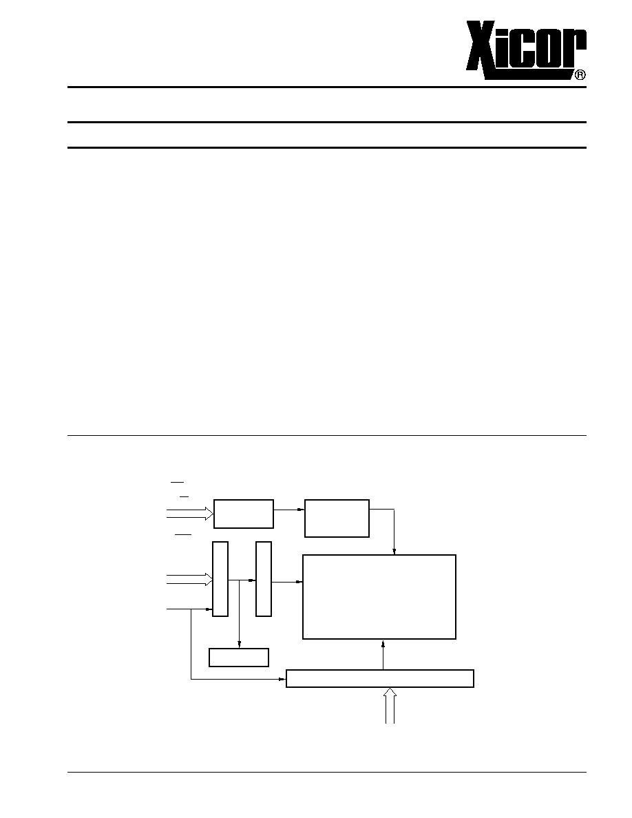
FUNCTIONAL DIAGRAM
CONTROL
LOGIC
SOFTWARE
DATA
PROTECT
CE, CE
R/W
E
SEL
A8≠A14
AS
L
A
T
C
H
E
S
D
E
C
O
D
E
Y DECODE
I/O & ADDRESS LATCHES AND BUFFERS
A/D0≠A/D7
X
32K x 8
E2PROM
6539 ILL F02.2
X68257
2
PIN DESCRIPTIONS
Address/Data (A/D
0
≠A/D
7
)
Multiplexed low-order addresses and data. The ad-
dresses flow into the device while AS is HIGH. After AS
transitions from a HIGH to LOW the addresses are
latched. Once the addresses are latched these pins
input data or output data depending on R/
W
,
SEL
, and
CE.
Addresses (A
8
≠A
14
)
High order addresses flow into the device when AS = V
IH
and are latched when AS goes LOW.
Chip Enable (
CE
)
The Chip Enable input must be LOW to enable all read/
write operations. When
CE
is HIGH, AS is LOW, and CE
is LOW, the X68257 is placed in the low power standby
mode.
Chip Enable (CE)
Chip Enable is active HIGH. When CE is used to select
the device, the CE must be tied HIGH.
Program Store Enable (
SEL
)
When the X68257 is to be used in a 68XX-based
system,
SEL
is tied to V
SS
.
Read/Write (R/
W
)
When the X68257 is to be used in a 68XX-based
system, R/
W
is tied directly to the microcontroller's R/
W
output.
Address Strobe (AS)
Addresses flow through the latches to address decoders
when AS is HIGH and are latched when AS transitions
from a HIGH to LOW.
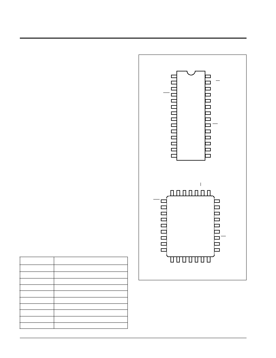
PIN CONFIGURATION
PIN NAMES
Symbol
Description
AS
Address Strobe
A/D
0
≠A/D
7
Address Inputs/Data I/O
A
8
≠A
14
Address Inputs
E
Enable Input
R/
W
Read/Write Input
CE,
CE
Chip Enable
SEL
Device Select--Connect to V
SS
V
SS
Ground
V
CC
Supply Voltage
NC
No Connect
6539 PGM T01.2
6539 FHD F01.3
A14
A12
AS
SEL
CE
NC
NC
NC
NC
NC
A/D0
A/D1
A/D2
VSS
1
2
3
4
5
6
7
8
9
10
11
12
13
14
28
27
26
25
24
23
22
21
20
19
18
17
16
15
VCC
R/W
A13
A8
A9
A11
E
A10
CE
A/D7
A/D6
A/D5
A/D4
A/D3
PDIP
SOIC
X68257
6539 FHD F01A.5
AS
SEL
CE
NC
NC
NC
NC
NC
NC
A/D0
A8
A9
A11
NC
E
A10
CE
A/D7
A/D6
A
12
A
14
V
CC
R/W
A
13
A/D
1
A/D
2
V
SS
NC
A/D
3
A/D
4
A/D
5
3
2
1 32 31
15 16 17 18 19
5
6
7
8
9
10
11
12
28
27
26
25
24
23
22
X68257
PLCC
13
14
20
21
4
30
29
NC

X68257
3
PRINCIPLES OF OPERATION
The X68257 is a highly integrated peripheral device for
a wide variety of single-chip microcontrollers. The X68257
provides 32K-bytes of 5V E
2
PROM which can be used
either for program storage, data storage, or a combina-
tion of both, in systems based upon Von Neumann
(68XX) architectures. The X68257 incorporates the
interface circuitry normally needed to decode the control
signals and demultiplex the address/data bus to provide
a "seamless" interface.
The interface inputs on the X68257 are configured such
that it is possible to directly connect them to the proper
interface signals of the appropriate single-chip micro-
controller.
The X68257 features the industry standard 5V E
2
PROM
characteristics such as byte or page mode write and
Toggle Bit Polling.
DEVICE OPERATION
Motorola 68XX operation requires the microcontroller
AS, E, and R/
W
outputs to be tied to the X68257 AS, E,
and R/
W
inputs respectively.
The falling edge of AS will latch the addresses for both
a read and write operation. The state of the R/
W
output
determines the operation to be performed, with the E
signal acting as a data strobe.
If R/
W
is HIGH and CE is HIGH (read operation) data will
be output on A/D
0
≠A/D
7
after E transitions HIGH. If
R/
W
is LOW and CE is HIGH (write operation) data
present at A/D
0
≠A/D
7
will be strobed into the X68257 on
the HIGH to LOW transition of E.
Typical Application
6539 ILL F03.2
31
32
33
34
35
36
37
38
16
15
14
13
12
11
10
9
26
28
27
17
18
19
20
22
21
11
12
12
15
16
17
18
19
25
24
21
23
2
26
1
5
3
27
22
VCC
20
4
X68257
68HC11
U?
U?
CE
SEL
A/D0
A/D1
A/D2
A/D3
A/D4
A/D5
A/D6
A/D7
A8
A9
A10
A11
A12
A13
A14
CE
AS
R/W
E
PC0
PC1
PC2
PC3
PC4
PC5
PC6
PC7
PB0
PB1
PB2
PB3
PB4
PB5
PB6
PB7
AS
R/W
E
PE0
PE1
PE2
PE3
VRH
VRL
XTAL
EXTAL
RESET
IRQ
XIRQ
PA0
PA1
PA2
PA3
PA4
PA5
PA6
PA7
MODA
MODB
PD0
PD1
PD2
PD3
PD4
PD5
30
29
39
41
40
8
7
6
5
4
3
2
1
25
24
42
43
44
45
46
47
MISO
MOSI
SCK
SS

X68257
4
MODE SELECTION
CE
E
R/
W
Mode
I/O
Power
V
SS
X
X
Standby
High Z
Standby (CMOS)
LOW
X
X
Standby
High Z
Standby (TTL)
HIGH
HIGH
HIGH
Read
D
OUT
Active
HIGH
LOW
Write
D
IN
Active
6539 PGM T02.2
The rising edge of E starts a timer delaying the internal
programming cycle 100
µ
s. Therefore, each successive
write operation must begin within 100
µ
s of the last byte
written. The following waveforms illustrate the sequence
and timing requirements.
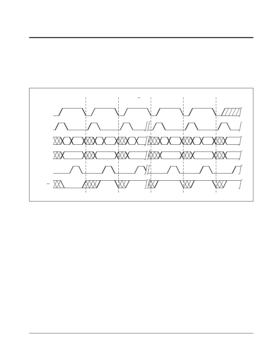
PAGE WRITE OPERATION
Regardless of the microcontroller employed, the X68257
supports page mode write operations. This allows the
microcontroller to write from 1 to 128 bytes of data to the
X68257. Each individual write within a page write opera-
tion must conform to the byte write timing requirements.
Page Write Timing Sequence for E Controlled Operation
Note:
(1) For each successive write within a page write cycle A
7
≠A
14
must be the same.
tBLC
CE
AS
A/D0≠A/D7
A8≠A14
E
R/W
AIN
DIN
An
OPERATION
BYTE 0
BYTE 1
BYTE 2
LAST BYTE
READ (1)(2)
AFTER tWC READY FOR
NEXT WRITE OPERATION
tWC
6539 FHD F07.1
AIN
DIN
AIN
DIN
AIN
DIN
AIN
DIN
AIN
ADDR
AIN
Next Address
An
An
An
An
X68257
5
subsequent attempts to read the device. When the
internal cycle is complete, the toggling will cease and the
device will be accessible for additional read or write
operations.
Toggle Bit Polling
Because the typical write timing is less than the specified
5ms, Toggle Bit Polling has been provided to determine
the early end of write. During the internal programming
cycle I/O
6
will toggle from "1" to "0" and "0" to "1" on
Toggle Bit Polling E Control
CE
AS
A/D0≠A/D7
A8≠A14
E
R/W
AIN
DIN
An
OPERATION
LAST BYTE
WRITTEN
I/O6=X
X68257 READY FOR
NEXT OPERATION
6539 FHD F08.2
AIN DOUT
AIN DOUT
AIN DOUT
AIN
AIN
ADDR
I/O6=X
I/O6=X
I/O6=X
DOUT
An
An
An
An
X68257
6
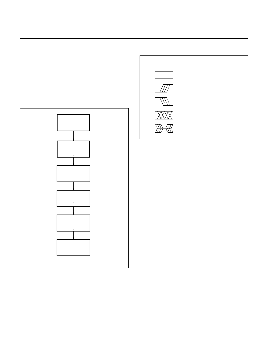
Software Data Protection
Software Data Protection (SDP) is employed to protect
the entire array against inadvertent writes. To write to
the X68257, a three-byte command sequence must
precede the byte(s) being written.
All write operations, both the command sequence and
any data write operations must conform to the page write
timing requirements.
Writing with SDP
SYMBOL TABLE
WAVEFORM
INPUTS
OUTPUTS
Must be
steady
Will be
steady
May change
from LOW
to HIGH
Will change
from LOW
to HIGH
May change
from HIGH
to LOW
Will change
from HIGH
to LOW
Don't Care:
Changes
Allowed
Changing:
State Not
Known
N/A
Center Line
is High
Impedance
6539 FHD F09.1
WRITE AA
TO 5555
WRITE 55
TO 2AAA
WRITE A0
TO 5555
PERFORM BYTE
OR PAGE WRITE
OPERATIONS
WAIT tWC
EXIT ROUTINE

X68257
7
ABSOLUTE MAXIMUM RATINGS*
Temperature under Bias .................. ≠65
∞
C to +135
∞
C
Storage Temperature ....................... ≠65
∞
C to +150
∞
C
Voltage on any Pin with
Respect to V
SS
.................................. ≠1V to +7V
D.C. Output Current ............................................. 5mA
Lead Temperature
(Soldering, 10 seconds) .............................. 300
∞
C
*COMMENT
Stresses above those listed under "Absolute Maximum
Ratings" may cause permanent damage to the device.
This is a stress rating only and the functional operation of
the device at these or any other conditions above those
indicated in the operational sections of this specification
is not implied. Exposure to absolute maximum rating
conditions for extended periods may affect device reli-
ability.
RECOMMENDED OPERATING CONDITIONS
Temperature
Min.
Max.
Commercial
0
∞
C
+70
∞
C
Industrial
≠40
∞
C
+85
∞
C
Military
≠55
∞
C
+125
∞
C
6539 PGM T03.1
Supply Voltage
Limits
X68257
5V
±
10%
6539 PGM T04.1
D.C. OPERATING CHARACTERISTICS (Over recommended operating conditions unless otherwise specified.)
Limits
Symbol
Parameter
Min.
Max.
Units
Test Conditions
I
CC
V
CC
Current (Active)
60
mA
CE = V
IL
, All I/O's = Open,
Other Inputs = V
CC
, AS = V
IH
I
SB1(CMOS)
V
CC
Current (Standby)
500
µ
A
CE = V
SS
,
All I/O's = Open,Other
Inputs = V
CC
≠ 0.3V, AS = V
SS
I
SB2(TTL)
V
CC
Current (Standby)
6
mA
CE = V
IH
, All I/O's = Open, Other
Inputs = V
IH
, AS = V
IL
I
LI
Input Leakage Current
10
µ
A
V
IN
= V
SS
to V
CC
I
LO
Output Leakage Current
10
µ
A
V
OUT
= V
SS
to V
CC
, E = V
IL
V
lL(1)
Input LOW Voltage
≠1
0.8
V
V
IH(1)
Input HIGH Voltage
2
V
CC
+ 0.5
V
V
OL
Output LOW Voltage
0.4
V
I
OL
= 2.1mA
V
OH
Output HIGH Voltage
2.4
V
I
OH
= ≠400
µ
A
6539 PGM T05.1
CAPACITANCE T
A
= +25
∞
C, f = 1MHz, V
CC
= 5V
Symbol
Test
Max.
Units
Conditions
C
I/O(2)
Input/Output Capacitance
10
pF
V
I/O
= 0V
C
IN(2)
Input Capacitance
6
pF
V
IN
= 0V
6539 PGM T06
POWER-UP TIMING
Symbol
Parameter
Max.
Units
t
PUR(2)
Power-Up to Read
1
ms
t
PUW(2)
Power-Up to Write
5
ms
6539 PGM T07
Notes: (1) V
IL
min. and V
IH
max. are for reference only and are not tested.
(2) This parameter is periodically sampled and not 100% tested.
X68257
8
A.C. CONDITIONS OF TEST
Input Pulse Levels
0V to 3V
Input Rise and
Fall Times
10ns
Input and Output
Timing Levels
1.5V
6539 PGM T08.1
Note: (3) This parameter is periodically sampled and not 100% tested.
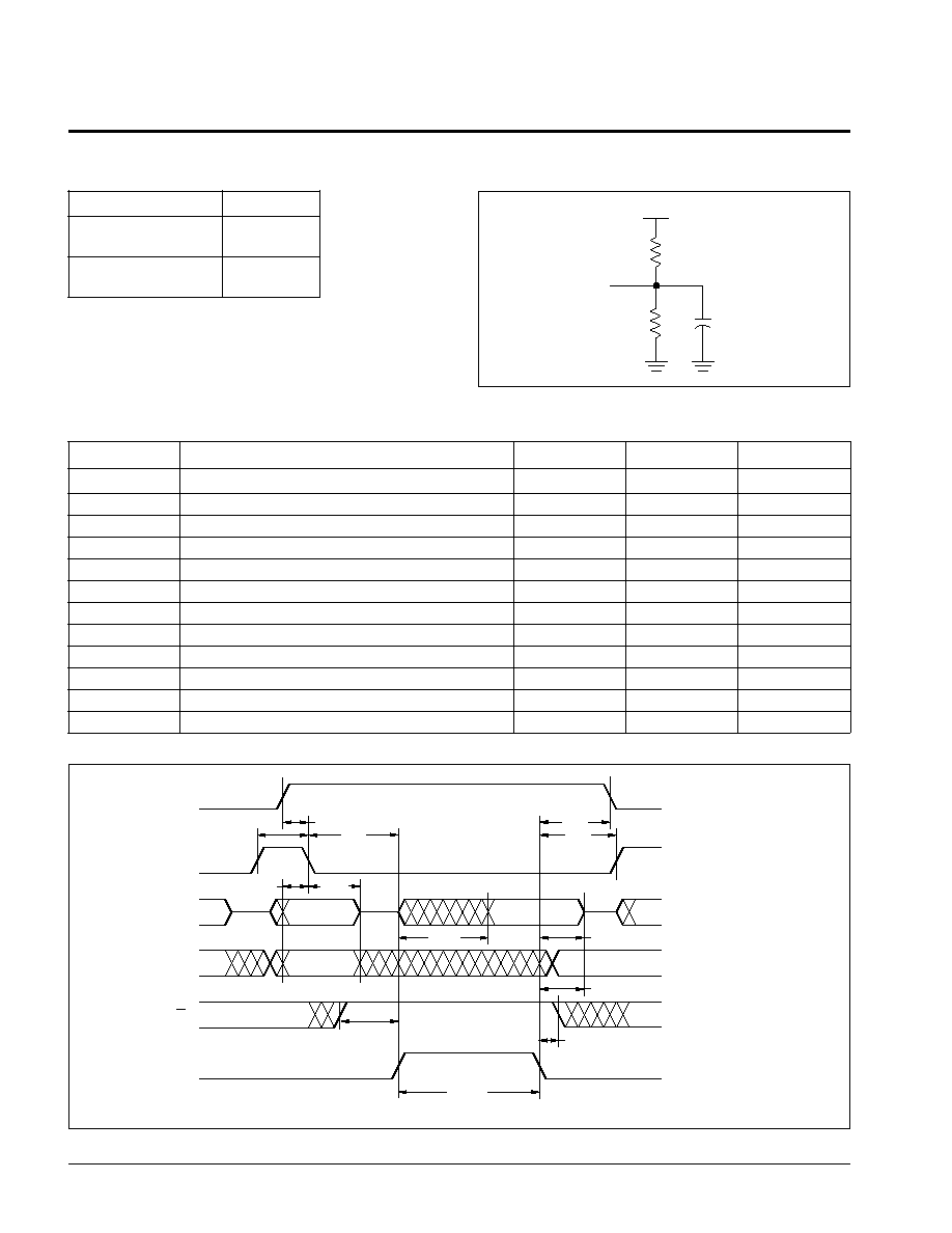
E Controlled Read Cycle
E Controlled Read Cycle
Symbol
Parameter
Min.
Max.
Units
PW
ASH
Address Strobe Pulse Width
80
ns
t
ASL
Address Setup Time
20
ns
t
AHL
Address Hold Time
30
ns
t
ACC
Data Access Time
120
ns
t
DHR
Data Hold Time
0
ns
t
CSL
CE Setup Time
7
ns
PW
EH
E Pulse Width
150
ns
t
ES
Enable Setup Time
30
ns
t
EH
E Hold Time
20
ns
t
RWS
R/
W
Setup Time
20
ns
t
HZ(3)
E LOW to High Z Output
50
ns
t
LZ(3)
E HIGH to Low Z Output
0
ns
6539 PGM T09.1
A.C. CHARACTERISTICS (Over the recommended operating conditions unless otherwise specified.)
TEST CIRCUIT
6539 FHD F04.2
5V
1.92K
100pF
OUTPUT
1.37K
AS
A/D0≠A/D7
A8≠A14
R/W
AIN
DOUT
PWASH
CE
tCSL
tASL
tAHL
A8≠A14
tES
tACC
tDHR
PWEH
tRWS
tEH
tEH
tHZ
tEH
E
6539 FHD F05.2
X68257
9
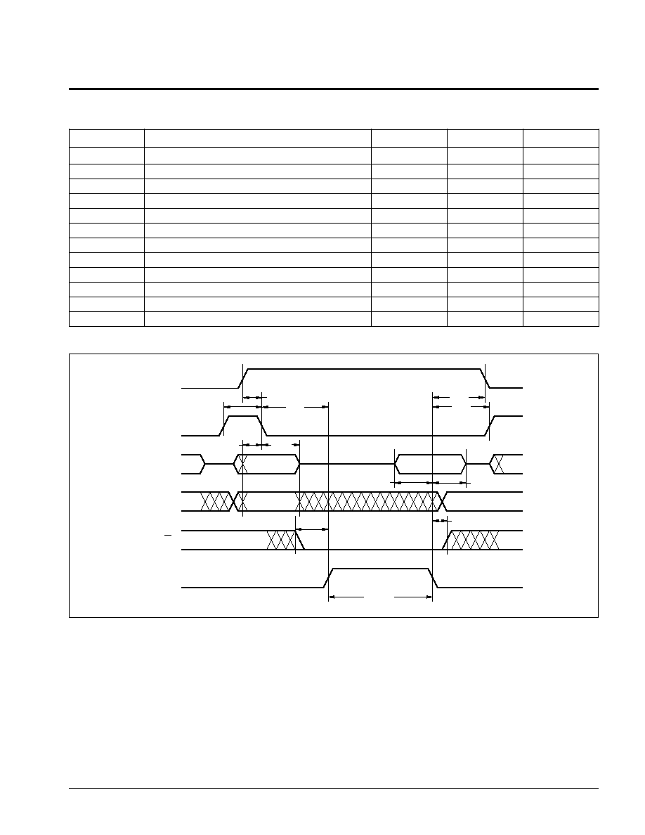
E Controlled Write Cycle
Symbol
Parameter
Min.
Max.
Units
PW
ASH
Address Strobe Pulse Width
80
ns
t
ASL
Address Setup Time
20
ns
t
AHL
Address Hold Time
30
ns
t
DSW
Data Setup Time
50
ns
t
DHW
Data Hold Time
30
ns
t
CSL
CE Setup Time
7
ns
PW
EH
E Pulse Width
120
ns
t
WC
Write Cycle Time
5
ms
t
ES
Enable Setup Time
30
ns
t
RWS
R/
W
Setup Time
20
ns
t
EH
E Hold Time
20
ns
t
BLC
Byte Load Time (Page Write)
0.5
100
µ
s
6539 PGM T10
E Controlled Write Cycle
Note: (4) t
WC
is the minimum cycle time to be allowed from the system perspective unless polling techniques are used. It is the maximum
time the device requires to automatically complete the internal write operation.
6539 FHD F06.2
6539 FHD F05.2
AS
A/D0≠A/D7
A8≠A14
R/W
AIN
DIN
PWASH
CE
tCSL
tASL
tAHL
A8≠A14
tES
tDSW
tDHW
PWEH
tRWS
tEH
tEH
tEH
E
X68257
10
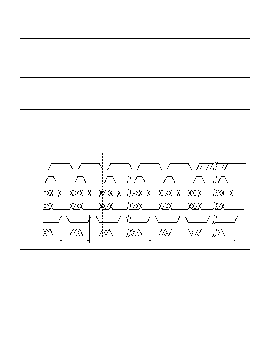
WR
Controlled Write Cycle
Symbol
Parameter
Min.
Max.
Units
t
LHLL
ALE Pulse Width
80
ns
t
AVLL
Address Setup Time
20
ns
t
LLAX
Address Hold Time
30
ns
t
DVWH
Data Setup Time
50
ns
t
WHDX
Data Hold Time
30
ns
t
ELLL
Chip Enable Setup Time
7
ns
t
WLWH
WR
Pulse Width
120
ns
t
WRS
WR
Setup Time
30
ns
t
WRH
WR
Hold Time
20
ns
t
BLC
Byte Load Time (Page Write)
0.5
100
µ
s
t
WC (7)
Write Cycle Time
5
ms
6539 PGM T11
WR
Controlled Write Timing Diagram
Note: (7) t
WC
is the minimum cycle time to be allowed from the system perspective unless polling techniques are used. It is the maximum
time the device requires to automatically complete the internal write operation.
tBLC
CE
AS
A/D0≠A/D7
A8≠A14
E
R/W
AIN
DIN
An
OPERATION
BYTE 0
BYTE 1
BYTE 2
LAST BYTE
READ (1)(2)
AFTER tWC READY FOR
NEXT WRITE OPERATION
tWC
6539 FHD F07.1
AIN
DIN
AIN
DIN
AIN
DIN
AIN
DIN
AIN
ADDR
AIN
Next Address
An
An
An
An
X68257
11
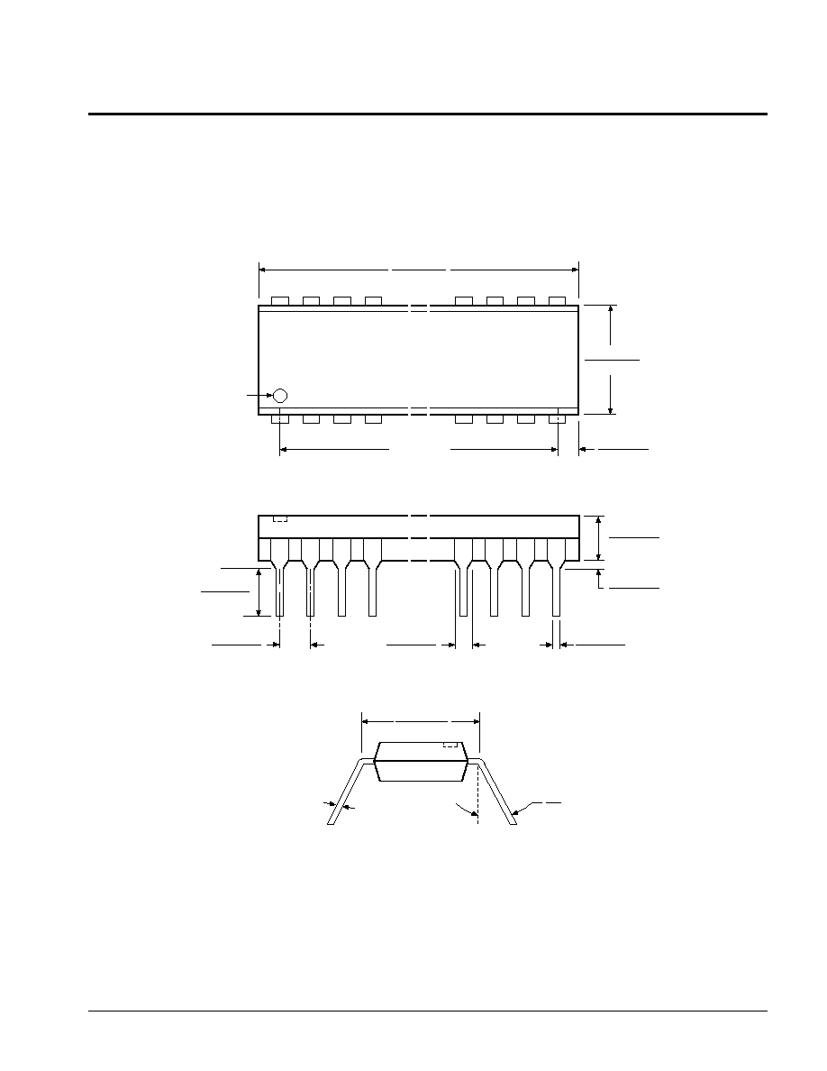
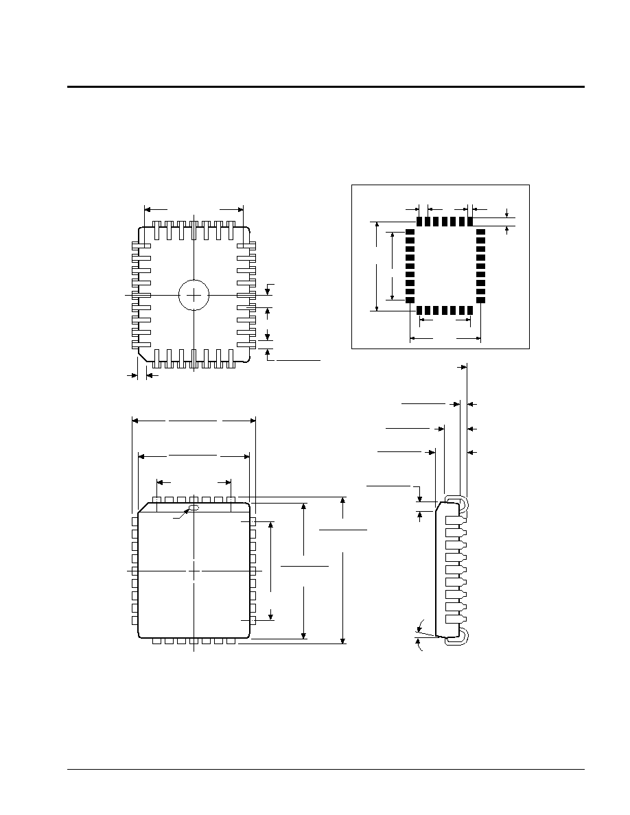
PACKAGING INFORMATION
3926 FHD F04
NOTE:
1. ALL DIMENSIONS IN INCHES (IN PARENTHESES IN MILLIMETERS)
2. PACKAGE DIMENSIONS EXCLUDE MOLDING FLASH
0.022 (0.56)
0.014 (0.36)
0.160 (4.06)
0.120 (3.05)
0.625 (15.88)
0.590 (14.99)
0.110 (2.79)
0.090 (2.29)
1.470 (37.34)
1.400 (35.56)
1.300 (33.02)
REF.
PIN 1 INDEX
0.160 (4.06)
0.125 (3.17)
0.030 (0.76)
0.015 (0.38)
PIN 1
SEATING
PLANE
0.065 (1.65)
0.040 (1.02)
0.557 (14.15)
0.510 (12.95)
0.085 (2.16)
0.040 (1.02)
0
∞
15
∞
28-LEAD PLASTIC DUAL IN-LINE PACKAGE TYPE P
TYP. 0.010 (0.25)

X68257
12
PACKAGING INFORMATION
28-LEAD PLASTIC SMALL OUTLINE GULL WING PACKAGE TYPE S
0.299 (7.59)
0.290 (7.37)
0.419 (10.64)
0.394 (10.01)
0.020 (0.508)
0.014 (0.356)
0.0200 (0.5080)
0.0100 (0.2540)
0.050 (1.270)
BSC
0.713 (18.11)
0.697 (17.70)
0.012 (0.30)
0.003 (0.08)
0.105 (2.67)
0.092 (2.34)
0.0350 (0.8890)
0.0160 (0.4064)
0.013 (0.32)
0.008 (0.20)
0
∞
≠ 8
∞
X 45
∞
3926 FHD F17
NOTES:
1. ALL DIMENSIONS IN INCHES (IN PARENTHESES IN MILLIMETERS)
2. FORMED LEAD SHALL BE PLANAR WITH RESPECT TO ONE ANOTHER WITHIN 0.004 INCHES
SEATING PLANE
BASE PLANE
0.42" MAX
0.030" TYPICAL
28 PLACES
0.050" TYPICAL
0.050"
TYPICAL
FOOTPRINT
X68257
13
PACKAGING INFORMATION
0.021 (0.53)
0.013 (0.33)
0.420 (10.67)
0.050 (1.27) TYP.
TYP. 0.017 (0.43)
0.045 (1.14) x 45
∞
0.300 (7.62)
REF.
0.453 (11.51)
0.447 (11.35)
TYP. 0.450 (11.43)
0.495 (12.57)
0.485 (12.32)
TYP. 0.490 (12.45)
PIN 1
0.400
(10.16)
REF.
0.553 (14.05)
0.547 (13.89)
TYP. 0.550 (13.97)
0.595 (15.11)
0.585 (14.86)
TYP. 0.590 (14.99)
3
∞
TYP.
0.048 (1.22)
0.042 (1.07)
0.140 (3.56)
0.100 (2.45)
TYP. 0.136 (3.45)
0.095 (2.41)
0.060 (1.52)
--
0.015 (0.38)
SEATING PLANE
±
0.004 LEAD
CO ≠ PLANARITY
3926 FHD F13
32-LEAD PLASTIC LEADED CHIP CARRIER PACKAGE TYPE J
NOTES:
1. ALL DIMENSIONS IN INCHES (IN PARENTHESES IN MILLIMETERS)
2. DIMENSIONS WITH NO TOLERANCE FOR REFERENCE ONLY
0.510"
TYPICAL
0.050"
TYPICAL
0.050"
TYPICAL
0.300"
REF
FOOTPRINT
0.400"
0.410"
0.030" TYPICAL
32 PLACES

X68257
14
ORDERING INFORMATION
LIMITED WARRANTY
Devices sold by Xicor, Inc. are covered by the warranty and patent indemnification provisions appearing in its Terms of Sale only. Xicor, Inc. makes
no warranty, express, statutory, implied, or by description regarding the information set forth herein or regarding the freedom of the described
devices from patent infringement. Xicor, Inc. makes no warranty of merchantability or fitness tor any purpose. Xicor, Inc. reserves the right to
discontinue production and change specifications and prices at any time and without notice.
Xicor, Inc. assumes no responsibility for the use of any circuitry other than circuitry embodied in a Xicor, Inc. product. No other circuits, patents,
licenses are implied.
US. PATENTS
Xicor products are covered by one or more of the following U.S. Patents: 4,263,664; 4,274,012; 4,300,212; 4,314,265; 4,326,134; 4,393,481;
4,404,475; 4,450,402; 4,486,769; 4,488,060; 4,520,461; 4,533,846; 4,599,706; 4,617,652; 4,668,932; 4,752,912; 4,829,482; 4,874,967; 4,883,976;
4,980,859; 5,012,132; 5,003,197; 5,023,694. Foreign patents and additional patents pending.
LIFE RELATED POLICY
In situations where semiconductor component failure may endanger life, system designers using this product should design the system with
appropriate error detection and correction, redundancy and back-up features to prevent such an occurrence.
Xicor's products are not authorized for use as critical components in life support devices or systems.
1. Life support devices or systems are devices or systems which, (a) are intended for surgical implant into the body, or (b) support or sustain life,
and whose failure to perform, when properly used in accordance with instructions for use provided in the labeling, can be reasonably expected
to result in a significant injury to the user.
2. A critical component is any component of a life support device or system whose failure to perform can be reasonably expected to cause the failure
of the life support device or system, or to affect its satety or effectiveness.
Device
X68257 X X
Temperature Range
Blank = Commercial = 0
∞
C to +70
∞
C
I = Industrial = ≠40
∞
C to +85
∞
C
M = Military = ≠55
∞
C to +125
∞
C
Package
P = 28-Lead Plastic DIP
S = 28-Lead SOIC
J = 32-Lead PLCC