©
Xicor, 1995, 1996 Patents Pending
7053 8/13/97 T0/C0/D0 SH
1
Characteristics subject to change without notice
4 Megabit Puma Module
XM28C040P
512K x 8 Bit
High Density 5 Volt Byte Alterable Nonvolatile Memory Array
FEATURES
∑ High Density Memory Module
--150ns, 200ns, and 250ns Access Times
Available
--4 Megabit Memory in 1 square inch.
∑ Flexible Multiplane Architecture
--Four Separate Chip Selects
--32 Separate I/Os
∑ User Configurable I/Os--x8, x16, or x32
∑ User Configurable Page Size--64 Double-
words, 128 Words, or 256 Bytes
--Concurrent Read/Write Operations
∑ Able to Continue Reading During a
Nonvolatile Write Cycle.
∑ 5 Volt Byte or Page Alterable
--No Erase Before Write
∑ Software Data Protection
∑ Early End of Write Polling
--DATA Polling
--Toggle Bit Polling
∑ High Reliability
--Endurance: 100,000 Cycles
--Data Retention: 100 Years
DESCRIPTION
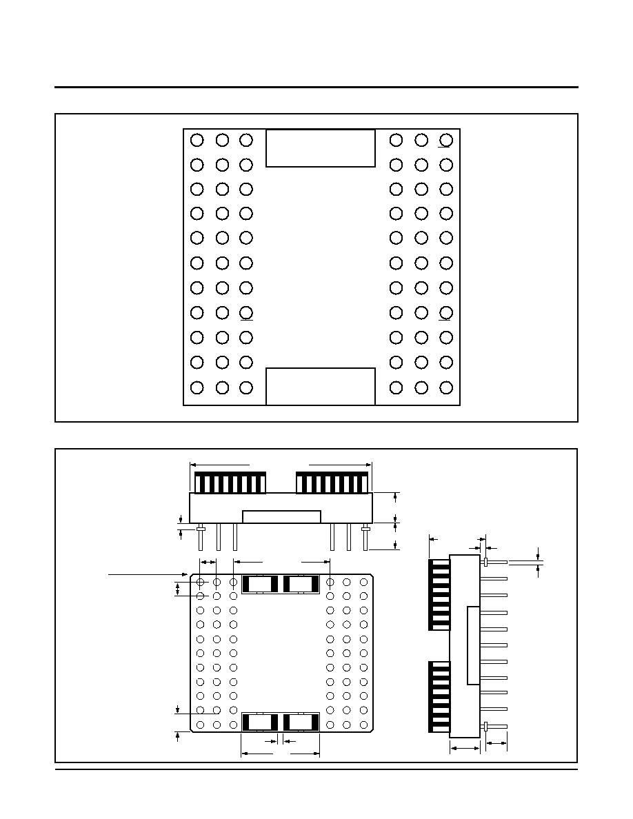
The XM28C040P is a high density CMOS byte alter-
able nonvolatile memory array constructed on a co-
fired ceramic substrate using Xicor's 128K x 8 compo-
nents in 32-pad leadless chip carriers. The Substrate is
a 66-pin ceramic pin grid array.
The module is configured with four separate chip
enable and write enable inputs and 32 separate I/Os.
This, along with the small footprint, provides the end
user with a large degree of flexibility in board layout and
memory configuration. In addition, with the large num-
ber of pins and the growth path being implemented, the
module will be able to grow to 16 megabits.
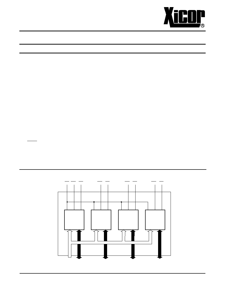
FUNCTIONAL DIAGRAM
128K x 8
128K x 8
128K x 8
128K x 8
OE WE1 CE1
WE2 CE2
WE3 CE3
WE4 CE4
A0-A16 I/O0-I/O7
I/O8-I/O15
I/O16-I/O23
I/O24-I/O31
XM28C040P
4
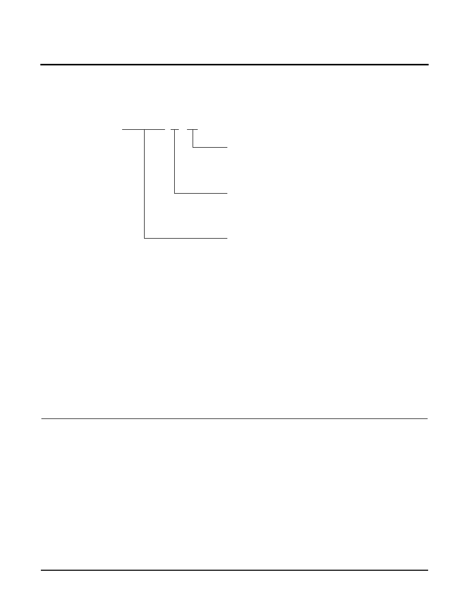
ORDERING INFORMATION
XM28C040P X
X
Devices
Access Time
15 = 150ns
20 = 200ns
25 = 250ns
Temperature Range
Blank = Commercial = 0
∞
C to +70
∞
C
I = Industrial = ≠40
∞
C to +85
∞
C
M = Military = ≠55
∞
C to +125
∞
C
P = 66 Pin PUMA Module
≠
LIMITED WARRANTY
Devices sold by Xicor, Inc. are covered by the warranty and patent indemnification provisions appearing in its Terms of Sale only. Xicor, Inc. makes no warranty,
express, statutory, implied, or by description regarding the information set forth herein or regarding the freedom of the described devices from patent infringement.
Xicor, Inc. makes no warranty of merchantability or fitness for any purpose. Xicor, Inc. reserves the right to discontinue production and change specifications and
prices at any time and without notice.
Xicor, Inc. assumes no responsibility for the use of any circuitry other than circuitry embodied in a Xicor, Inc. product. No other circuits, patents, licenses are implied.
U.S. PATENTS
Xicor products are covered by one or more of the following U.S. Patents: 4,263,664; 4,274,012; 4,300,212; 4,314,265; 4,326,134; 4,393,481; 4,404,475; 4,450,402;
4,486,769; 4,488,060; 4,520,461; 4,533,846; 4,599,706; 4,617,652; 4,668,932; 4,752,912; 4,829, 482; 4,874, 967; 4,883, 976. Foreign patents and additional pat-
ents pending.
LIFE RELATED POLICY
In situations where semiconductor component failure may endanger life, system designers using this product should design the system with appropriate error detec-
tion and correction, redundancy and back-up features to prevent such an occurrence.
Xicor's products are not authorized for use in critical components in life support devices or systems
1.
Life support devices or systems are devices or systems which, (a) are intended for surgical implant into the body, or (b) support or sustain life, and whose fail-
ure to perform, when properly used in accordance with instructions for use provided in the labeling, can be reasonably expected to result in a significant injury to the
user.
2.
A critical component is any component of a life support device or system whose failure to perform can be reasonably expected to cause the failure of the life
support device or system, or to affect its safety or effectiveness.