 | –≠–ª–µ–∫—Ç—Ä–æ–Ω–Ω—ã–π –∫–æ–º–ø–æ–Ω–µ–Ω—Ç: M16450 | –°–∫–∞—á–∞—Ç—å:  PDF PDF  ZIP ZIP |
January 12, 1998
1
Virtual IP Group, Inc.
1094 E. Duane Ave., Suite 211
Sunnyvale, CA 94086 USA
Phone:
+1 408-733-3344
Fax:
+1 408-733-9922
E-mail:
sales@virtualipgroup.com
URL: www.virtualipgroup.com
Features
∑
Available under terms of the SignOnce IP License
∑
Functionally compatible to NS16450
∑
Complete asynchronous communication protocol
including:
-
5, 6, 7 or 8 bit data transmission
-
Even/odd or no parity bit generation and detection
-
Start and stop bit generation and detection
-
Line break detection and generation
-
Receiver overrun and framing errors detection
-
Communications rates of upto 56K baud
∑
Internal programmable baud rate generator
∑
Buffered transmit and receive registers
∑
Exception handling using interrupt/polled modes
∑
Internal diagnostic capabilities with loopback
∑
Modem handshake capability using CTS, RTS, DSR,
DTR, RI and DCD signals
∑
Complete status reporting capabilities
∑
Line break generation and detection
Applications
∑
Serial Communication Port
∑
Modem Interface port
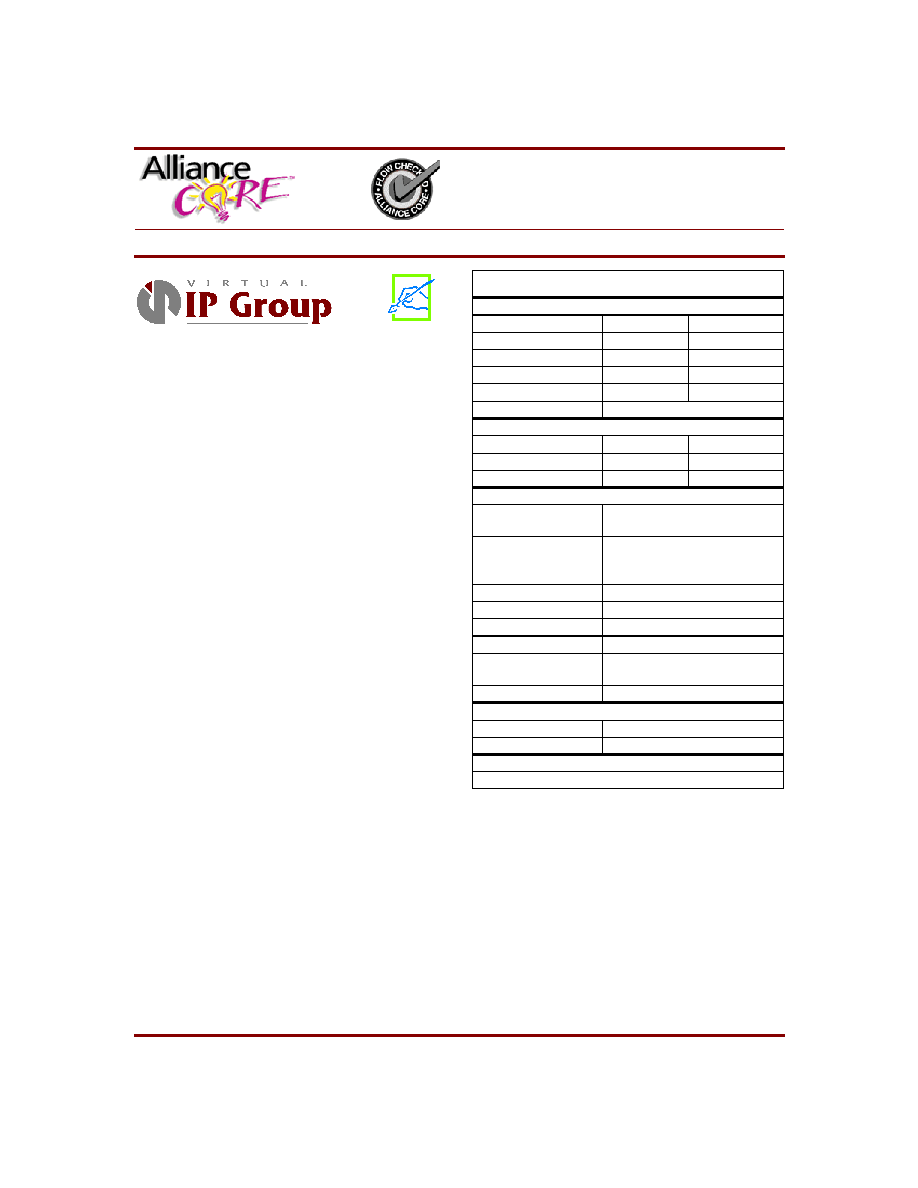
AllianceCORETM Facts
Core Specifics
Device Family
Spartan
XC4000E
CLBs Used
188
188
IOBs Used
34
1
34
1
CLKIOBs Used
4
4
System Clock fmax
18.4 MHz
18.4 MHz
Device Features Used
Global Buffers
Supported Devices/Resources Remaining
I/O
CLBs
XCS40PQ240-3
155
1
596
XC4020EHQ240-2
155
1
596
Provided with Core
Documentation
Core Design Document
Designers application note
Design File Formats
.ngd, XNF netlist
Verilog Source RTL
available extra
Constraint Files
.cst file, xactinit.dat.
Verification Tool
Test Vectors
Schematic Symbols
None
Evaluation Model
None
Reference designs &
application notes
FPGA Design Document
Additional Items
Evaluation board available extra
Design Tool Requirements
Xilinx Core Tools
Alliance 1.3
Entry/Verification Tool
Verilog RTL/Verilog XL simulator
Support
Support provided by Virtual IP Group, Inc.
Note:
1. Assuming all core signals are routed off chip.
M16450 Universal Asynchronous
Receiver/Transmitter
January 12, 1998
Product Specification

M16450 Universal Asynchronous Receiver/Transmitter
2
January 12, 1998
General Description
M16C450 interfaces with a microcontroller or microproces-
sor on one side and serial communications equipment on
the other. It provides full modem control through input and
output signals for easy handshaking with modems during
communication. Internal registers provide full programma-
bility of serial asynchronous communication parameters.
This core is functionally compatible to the National Semi-
conductor NS16450.
Functional Description
The functional Block Diagram is shown in Figure 1. The
internal modules are explained below.
System Interface and Control Block
This block supports the Processor interface and generates
the internal system level signals for proper functioning.
LSR and LCR Block
This block holds the Line Status and Line Control Regis-
ters. These two registers control communication for the
core.
Interrupt Control Block
This block handles all interrupt capabilities for the core.
Figure 1: M16450 Block Diagram

January 12, 1998
3
Eureka Technology, Inc.
Transmit Block
This block controls serial data transmission as per pro-
grammed parameters.
Baud Rate Generator Block
This block generates the Baud Rate Clock for the transmit-
ter section of the core. This clock can also be used by the
receiver block connecting BAUDOUT to RCLK.
Receiver Block
This block handles reception for the core. The clock for this
block is provided by RCLK. This clock should be 16 times
the baud rate.
Modem Control Logic Block
This block handles modem handshaking for the core.
These signals can be used for communication or as gen-
eral purpose signals. The modem control register resides in
this block, providing internal diagnostic capability.
Verification Methods
The core has been tested with in-house developed simula-
tion test vectors that are provided with the core. Assembly
level 80x86 programs were used to test the functionality of
the FPGA using a hardware evaluation board.
Recommended Design Experience
Knowledge of interface with Microprocessor based sys-
tems is required. The user must be familiar with HDL
design methodology as well as instantiation of Xilinx
netlists in a hierarchical design environment. Usage of Alli-
ance or Foundation tools is required.
Core Modifications
Modifications can be done to remove the internal baud rate
generator, or to strip off either transmitter or receiver.
These modifications can be performed by Virtual IP Group,
Inc. for additional cost.
Available Support Products
The FPGA Design Document included with the core gives
directions of constructing a general purpose FPGA evalua-
tion daughter board that can be plugged in to a standard
port socket on the target system through a flat cable.
Ordering Information
This AllianceCORE product is available from Xilinx Alli-
anceCORE partner, Virtual IP Group, Inc., under terms of
the SignOnce IP License. To learn about the SignOnce IP
License program, contact Virtual IP Group, visit www.xil-
inx.com/ipcenter/signonce.htm, or write to commonli-
cense@xilinx.com.
Please contact Virtual IP Group, Inc. for pricing and addi-
tional information about this AllianceCORE product.
Related Information
Refer to Specification Document for programming of this
core for a typical application in a system. The user is
required to refer to Designer's application note for integrat-
ing this core with other cores.
Xilinx Programmable Logic
For information on Xilinx programmable logic or develop-
ment system software, contact your local Xilinx sales office,
or:
Xilinx, Inc.
2100 Logic Drive
San Jose, CA 95124
Phone:
+1 408-559-7778
Fax:
+1 408-559-7114
URL:
www.xilinx.com
For general Xilinx literature, contact:
Phone:
+1 800-231-3386 (inside the US)
+1 408-879-5017 (outside the US)
E-mail:
literature@xilinx.com

M16450 Universal Asynchronous Receiver/Transmitter
4
January 12, 1998
Pinout
The pinout has not been fixed to a specific FPGA/IO allow-
ing flexibility with the user application. A pinout is sug-
gested for use with a user-constructible evaluation board.
Information for this is in the FPGA Design Document
included with the core. Signal names are provided in the
block diagram shown in Figure 1 and Table 1.
Table 1:
Signal
Signal
Direction
Description
System Interface Signals
A0, A1, A2
Input
Address signals to select an internal register for read/write operations.
CS0-2
Input
Chip Select. CS0 and CS1 are active high, CS2 is active low.
ADS
Input
Address Strobe. Chip Select and address signals are latched internally on rising edge of
ADS
.
Pulled low if unused.
MR
Input
Master Reset, active high.
RD
Input
Read Control, active high. Pulled low if unused.
RD
Input
Read Control, active low. Pulled high if unused.
WR
Input
Write Control, active high. Pulled low if unused.
WR
Input
Write Control, active low. Pulled high if unused.
DDIS
Output
Driver DISable signal, driven low, when core outputs data. Used to control data flow direction
in transceiver or, tristate buffers enable control.
CSOUT
Output
Indicates read/write selection of UART. Active high and remains high when UART is selected
through chip select inputs.
XIN
Input
Master clock input.
XOUT
Input
Master clock output, inverted from XIN.
D7 - D0
In/Out
Bidirectional databus carries data to be written to internal registers; also reports status of reg-
isters during read cycle.
Modem Interface Signals
RTS
Output
Active low REQUEST TO SEND indicates UART is ready to exchange data. System controls
this pin bit in modem control register.
CTS
Input
Active low CLEAR TO SEND indicates modem is ready to exchange data. Present state mon-
itored by reading MSR.
DTR
Output
Active low DATA TERMINAL READY tells modem that UART is ready to establish commu-
nication link. System controls this pin through bit in MSR.r.
DSR
Input
Active low DATA SET READY indicates modem is ready to handshake with core. Present
state monitored by reading MSR.
DCD
Input
Active low DATA CARRIER DETECT indicates modem has detected carrier on communica-
tions line. Present state monitored by reading MSR.
RI
Input
Active low RING INDICATOR indicates modem has detected ring signal. Present state mon-
itored by reading MSR.
OUT1-2
Output
General purpose outputs. System controls these pins by through bit in MSR.
Transmit/Receive Signals
SOUT
Output
Serial data output from transmitter block.
RCLK
Input
Input receive clock, should be 16 times communications baud rate.
SIN
Input
Serial data input for receiver block.
Other Signals
INTR
Output
Active high interrupt signal.
BAUDOUT
Output
Baud rate generator output clock. 16 times programmed communication baud rate.