© 2001 Xilinx, Inc. All rights reserved. All Xilinx trademarks, registered trademarks, patents, and disclaimers are as listed at
http://www.xilinx.com/legal.htm
.
All other trademarks and registered trademarks are the property of their respective owners. All specifications are subject to change without notice.
DS031-1 (v1.7) October 2, 2001
www.xilinx.com
Module 1 of 4
Advance Product Specification
1-800-255-7778
1
Summary of Virtex
Æ
-II Features
∑
Industry First Platform FPGA Solution
∑
IP-ImmersionTM Architecture
-
Densities from 40K to 8M system gates
-
420 MHz internal clock speed (Advance Data)
-
840+ Mb/s I/O (Advance Data)
∑
SelectRAMTM Memory Hierarchy
-
3 Mb of True Dual-PortTM RAM in 18-Kbit block
SelectRAM resources
-
Up to 1.5 Mb of distributed SelectRAM resources
-
High-performance interfaces to external memory
∑
DDR-SDRAM interface
∑
FCRAM interface
∑
QDRTM-SRAM interface
∑
Sigma RAM interface
∑
Arithmetic Functions
-
Dedicated 18-bit x 18-bit multiplier blocks
-
Fast look-ahead carry logic chains
∑
Flexible Logic Resources
-
Up to 93,184 internal registers / latches with Clock
Enable
-
Up to 93,184 look-up tables (LUTs) or cascadable
16-bit shift registers
-
Wide multiplexers and wide-input function support
-
Horizontal cascade chain and Sum-of-Products
support
-
Internal 3-state bussing
∑
High-Performance Clock Management Circuitry
-
Up to 12 DCM (Digital Clock Manager) modules
∑
Precise clock de-skew
∑
Flexible frequency synthesis
∑
High-resolution phase shifting
-
16 global clock multiplexer buffers
∑
Active InterconnectTM Technology
-
Fourth generation segmented routing structure
-
Predictable, fast routing delay, independent of
fanout
∑
SelectI/O-UltraTM Technology
-
Up to 1,108 user I/Os
-
19 single-ended standards and six differential
standards
-
Programmable sink current (2 mA to 24 mA) per I/O
-
Digitally Controlled Impedance (DCI) I/O: on-chip
termination resistors for single-ended I/O standards
-
PCI-X @ 133 MHz, PCI @ 66 MHz and 33 MHz
compliance, and CardBus compliant
-
Differential Signaling
∑
840 Mb/s Low-Voltage Differential Signaling I/O
(LVDS) with current mode drivers
∑
Bus LVDS I/O
∑
Lightning Data Transport (LDT) I/O with current
driver buffers
∑
Low-Voltage Positive Emitter-Coupled Logic
(LVPECL) I/O
∑
Built-in DDR Input and Output registers
-
Proprietary high-performance SelectLinkTM
Technology
∑
High-bandwidth data path
∑
Double Data Rate (DDR) link
∑
Web-based HDL generation methodology
∑
Supported by Xilinx FoundationTM and AllianceTM
Series Development Systems
-
Integrated VHDL and Verilog design flows
-
Compilation of 10M system gates designs
-
Internet Team Design (ITD) tool
∑
SRAM-Based In-System Configuration
-
Fast SelectMAPTM configuration
-
Triple Data Encryption Standard (DES) security
option (Bitstream Encryption)
-
IEEE1532 support
-
Partial reconfiguration
-
Unlimited re-programmability
-
Readback capability
∑
0.15 µm 8-Layer Metal process with 0.12 µm
high-speed transistors
∑
1.5 V (V
CCINT
) core power supply, dedicated 3.3 V
V
CCAUX
auxiliary and V
CCO
I/O power supplies
∑
IEEE 1149.1 compatible boundary-scan logic support
∑
Flip-Chip and Wire-Bond Ball Grid Array (BGA)
packages in three standard fine pitches (0.80mm,
1.00mm, and 1.27mm)
∑
100% factory tested
0
Virtex-II 1.5V
Field-Programmable Gate Arrays
DS031-1 (v1.7) October 2, 2001
0
0
Advance Product Specification
R
Virtex-II 1.5V Field-Programmable Gate Arrays
R
Module 1 of 4
www.xilinx.com
DS031-1 (v1.7) October 2, 2001
2
1-800-255-7778
Advance Product Specification
General Description
The Virtex-II family is a platform FPGA developed for high
performance from low-density to high-density designs that
are based on IP cores and customized modules. The family
delivers complete solutions for telecommunication, wire-
less, networking, video, and DSP applications, including
PCI, LVDS, and DDR interfaces.
The leading-edge 0.15µm / 0.12µm CMOS 8-layer metal
process and the Virtex-II architecture are optimized for high
speed with low power consumption. Combining a wide vari-
ety of flexible features and a large range of densities up to
10 million system gates, the Virtex-II family enhances pro-
grammable logic design capabilities and is a powerful alter-
native to mask-programmed gates arrays. As shown in
Table 1
, the Virtex-II family comprises 12 members, ranging
from 40K to 10M system gates.
Packaging
Offerings include ball grid array (BGA) packages with
0.80mm, 1.00mm, and 1.27mm pitches. In addition to tradi-
tional wire-bond interconnects, flip-chip interconnect is used
in some of the BGA offerings. The use of flip-chip intercon-
nect offers more I/Os than is possible in wire-bond versions
of the similar packages. Flip-Chip construction offers the
combination of high pin count with high thermal capacity.
Table 2
shows the maximum number of user I/Os available.
The Virtex-II device/package combination table (
Table 6
at
the end of this section) details the maximum number of I/Os
for each device and package using wire-bond or flip-chip
technology.
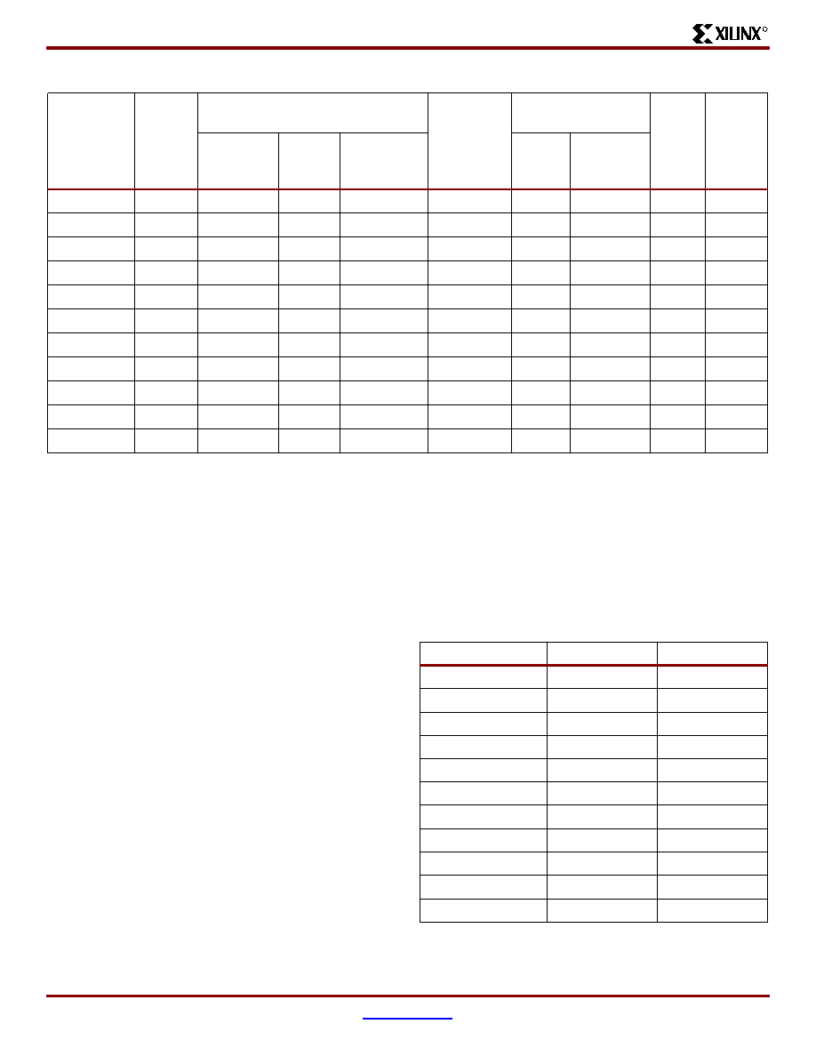
Table 1:
Virtex-II Field-Programmable Gate Array Family Members
Device
System
Gates
CLB
(1 CLB = 4 slices = Max 128 bits)
Multiplier
Blocks
SelectRAM Blocks
DCMs
Max I/O
Pads
(1)
Array
Row x Col.
Slices
Maximum
Distributed
RAM Kbits
18-Kbit
Blocks
Max RAM
(Kbits)
XC2V40
40K
8 x 8
256
8
4
4
72
4
88
XC2V80
80K
16 x 8
512
16
8
8
144
4
120
XC2V250
250K
24 x 16
1,536
48
24
24
432
8
200
XC2V500
500K
32 x 24
3,072
96
32
32
576
8
264
XC2V1000
1M
40 x 32
5,120
160
40
40
720
8
432
XC2V1500
1.5M
48 x 40
7,680
240
48
48
864
8
528
XC2V2000
2M
56 x 48
10,752
336
56
56
1,008
8
624
XC2V3000
3M
64 x 56
14,336
448
96
96
1,728
12
720
XC2V4000
4M
80 x 72
23,040
720
120
120
2,160
12
912
XC2V6000
6M
96 x 88
33,792
1,056
144
144
2,592
12
1,104
XC2V8000
8M
112 x 104
46,592
1,456
168
168
3,024
12
1,108
Notes:
1.
See details in
Table 2, "Maximum Number of User I/O Pads"
.
Table 2:
Maximum Number of User I/O Pads
Device
Wire-Bond
Flip-Chip
XC2V40
88
XC2V80
120
XC2V250
200
XC2V500
264
XC2V1000
328
432
XC2V1500
392
528
XC2V2000
456
624
XC2V3000
516
720
XC2V4000
912
XC2V6000
1,104
XC2V8000
1,108
Virtex-II 1.5V Field-Programmable Gate Arrays
R
DS031-1 (v1.7) October 2, 2001
www.xilinx.com
Module 1 of 4
Advance Product Specification
1-800-255-7778
3
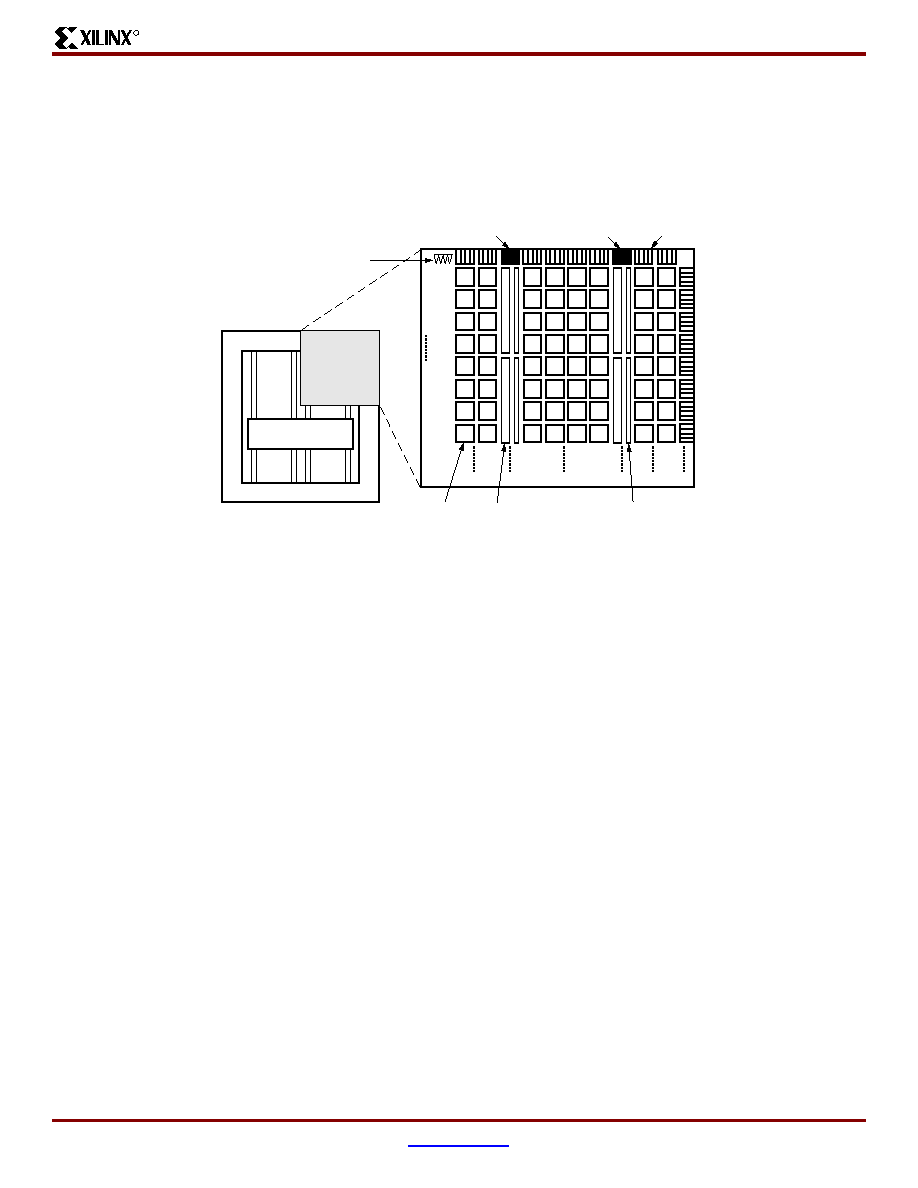
Architecture
Virtex-II Array Overview
Virtex-II devices are user-programmable gate arrays with various configurable elements. The Virtex-II architecture is
optimized for high-density and high-performance logic designs. As shown in
Figure 1
, the programmable device is
comprised of input/output blocks (IOBs) and internal configurable logic blocks (CLBs).
Programmable I/O blocks provide the interface between
package pins and the internal configurable logic. Most
popular and leading-edge I/O standards are supported by
the programmable IOBs.
The internal configurable logic includes four major elements
organized in a regular array.
∑
Configurable Logic Blocks (CLBs) provide functional
elements for combinatorial and synchronous logic,
including basic storage elements. BUFTs (3-state
buffers) associated with each CLB element drive
dedicated segmentable horizontal routing resources.
∑
Block SelectRAM memory modules provide large
18-Kbit storage elements of True Dual-Port RAM.
∑
Multiplier blocks are 18-bit x 18-bit dedicated
multipliers.
∑
DCM (Digital Clock Manager) blocks provide
self-calibrating, fully digital solutions for clock
distribution delay compensation, clock multiplication
and division, coarse and fine-grained clock phase
shifting.
A new generation of programmable routing resources called
Active Interconnect Technology interconnects all of these
elements. The general routing matrix (GRM) is an array of
routing switches. Each programmable element is tied to a
switch matrix, allowing multiple connections to the general
routing matrix. The overall programmable interconnection is
hierarchical and designed to support high-speed designs.
All programmable elements, including the routing
resources, are controlled by values stored in static memory
cells. These values are loaded in the memory cells during
configuration and can be reloaded to change the functions
of the programmable elements.
Virtex-II Features
This section briefly describes Virtex-II features.
Input/Output Blocks (IOBs)
IOBs are programmable and can be categorized as follows:
∑
Input block with an optional single-data-rate or
double-data-rate (DDR) register
∑
Output block with an optional single-data-rate or DDR
register, and an optional 3-state buffer, to be driven
directly or through a single or DDR register
∑
Bi-directional block (any combination of input and
output configurations)
These registers are either edge-triggered D-type flip-flops
or level-sensitive latches.
IOBs support the following single-ended I/O standards:
∑
LVTTL, LVCMOS (3.3 V, 2.5 V, 1.8 V, and 1.5 V)
∑
PCI-X at 133 MHz, PCI (3.3 V at 33 MHz and 66 MHz)
∑
GTL and GTLP
∑
HSTL (Class I, II, III, and IV)
Figure 1:
Virtex-II Architecture Overview
Global Clock Mux
DCM
DCM
IOB
CLB
Programmable I/Os
Block SelectRAM
Multiplier
Configurable Logic
DS031_28_100900
Virtex-II 1.5V Field-Programmable Gate Arrays
R
Module 1 of 4
www.xilinx.com
DS031-1 (v1.7) October 2, 2001
4
1-800-255-7778
Advance Product Specification
∑
SSTL (3.3 V and 2.5 V, Class I and II)
∑
AGP-2X
The digitally controlled impedance (DCI) I/O feature auto-
matically provides on-chip termination for each I/O element.
The IOB elements also support the following differential sig-
naling I/O standards:
∑
LVDS
∑
BLVDS (Bus LVDS)
∑
ULVDS
∑
LDT
∑
LVPECL
Two adjacent pads are used for each differential pair. Two or
four IOB blocks connect to one switch matrix to access the
routing resources.
Configurable Logic Blocks (CLBs)
CLB resources include four slices and two 3-state buffers.
Each slice is equivalent and contains:
∑
Two function generators (F & G)
∑
Two storage elements
∑
Arithmetic logic gates
∑
Large multiplexers
∑
Wide function capability
∑
Fast carry look-ahead chain
∑
Horizontal cascade chain (OR gate)
The function generators F & G are configurable as 4-input
look-up tables (LUTs), as 16-bit shift registers, or as 16-bit
distributed SelectRAM memory.
In addition, the two storage elements are either edge-trig-
gered D-type flip-flops or level-sensitive latches.
Each CLB has internal fast interconnect and connects to a
switch matrix to access general routing resources.
Block SelectRAM Memory
The block SelectRAM memory resources are 18 Kb of True
Dual-Port RAM, programmable from 16K x 1 bit to 512 x 36
bits, in various depth and width configurations. Each port is
totally synchronous and independent, offering three
"read-during-write" modes. Block SelectRAM memory is
cascadable to implement large embedded storage blocks.
Supported memory configurations for dual-port and sin-
gle-port modes are shown in
Table 3
.
A multiplier block is associated with each SelectRAM mem-
ory block. The multiplier block is a dedicated 18 x 18-bit
multiplier and is optimized for operations based on the block
SelectRAM content on one port. The 18 x 18 multiplier can
be used independently of the block SelectRAM resource.
Read/multiply/accumulate operations and DSP filter struc-
tures are extremely efficient.
Both the SelectRAM memory and the multiplier resource
are connected to four switch matrices to access the general
routing resources.
Global Clocking
The DCM and global clock multiplexer buffers provide a
complete solution for designing high-speed clocking
schemes.
Up to 12 DCM blocks are available. To generate de-skewed
internal or external clocks, each DCM can be used to elimi-
nate clock distribution delay. The DCM also provides 90-,
180-, and 270-degree phase-shifted versions of its output
clocks. Fine-grained phase shifting offers high-resolution
phase adjustments in increments of 1/256 of the clock
period. Very flexible frequency synthesis provides a clock
output frequency equal to any M/D ratio of the input clock
frequency, where M and D are two integers. For the exact
timing parameters, see
VirtexTM-II Electrical Characteris-
tics
.
Virtex-II devices have 16 global clock MUX buffers, with up
to eight clock nets per quadrant. Each global clock MUX
buffer can select one of the two clock inputs and switch
glitch-free from one clock to the other. Each DCM block is
able to drive up to four of the 16 global clock MUX buffers.
Routing Resources
The IOB, CLB, block SelectRAM, multiplier, and DCM ele-
ments all use the same interconnect scheme and the same
access to the global routing matrix. Timing models are
shared, greatly improving the predictability of the perfor-
mance of high-speed designs.
There are a total of 16 global clock lines, with eight available
per quadrant. In addition, 24 vertical and horizontal long
lines per row or column as well as massive secondary and
local routing resources provide fast interconnect. Virtex-II
buffered interconnects are relatively unaffected by net
fanout and the interconnect layout is designed to minimize
crosstalk.
Horizontal and vertical routing resources for each row or
column include:
∑
24 long lines
∑
120 hex lines
∑
40 double lines
∑
16 direct connect lines (total in all four directions)
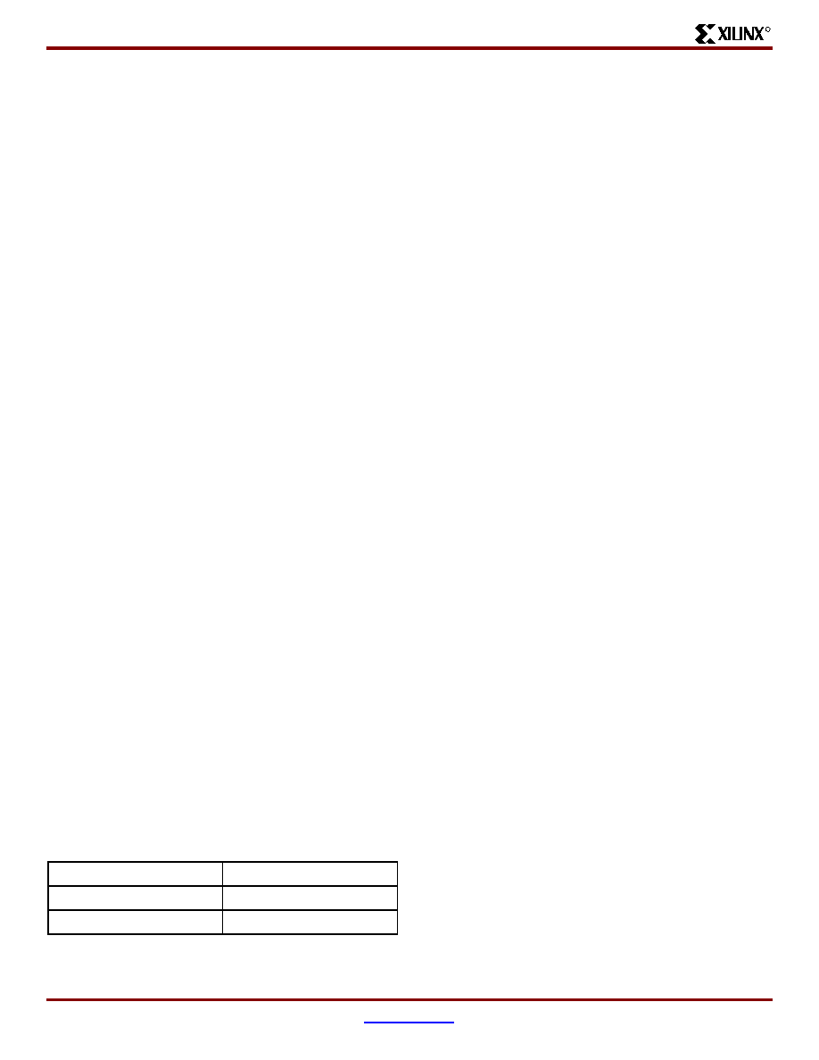
Table 3:
Dual-Port And Single-Port Configurations
16K x 1 bit
2K x 9 bits
8K x 2 bits
1K x 18 bits
4K x 4 bits
512 x 36 bits
Virtex-II 1.5V Field-Programmable Gate Arrays
R
DS031-1 (v1.7) October 2, 2001
www.xilinx.com
Module 1 of 4
Advance Product Specification
1-800-255-7778
5
Boundary Scan
Boundary scan instructions and associated data registers
support a standard methodology for accessing and config-
uring Virtex-II devices that complies with IEEE standards
1149.1 - 1993 and 1532. A system mode and a test mode
are implemented. In system mode, a Virtex-II device per-
forms its intended mission even while executing non-test
boundary-scan instructions. In test mode, boundary-scan
test instructions control the I/O pins for testing purposes.
The Virtex-II Test Access Port (TAP) supports BYPASS,
PRELOAD, SAMPLE, IDCODE, and USERCODE non-test
instructions. The EXTEST, INTEST, and HIGHZ test instruc-
tions are also supported.
Configuration
Virtex-II devices are configured by loading data into internal
configuration memory, using the following five modes:
∑
Slave-serial mode
∑
Master-serial mode
∑
Slave SelectMAP mode
∑
Master SelectMAP mode
∑
Boundary-Scan mode (IEEE 1532)
A Data Encryption Standard (DES) decryptor is available
on-chip to secure the bitstreams. One or two triple-DES key
sets can be used to optionally encrypt the configuration
information.
Readback and Integrated Logic Analyzer
Configuration data stored in Virtex-II configuration memory
can be read back for verification. Along with the configura-
tion data, the contents of all flip-flops/latches, distributed
SelectRAM, and block SelectRAM memory resources can
be read back. This capability is useful for real-time debug-
ging.
The Integrated Logic Analyzer (ILA) core and software pro-
vides a complete solution for accessing and verifying
Virtex-II devices.
Virtex-II Device/Package Combinations
and Maximum I/O
Wire-bond and flip-chip packages are available.
Table 4
and
Table 5
show the maximum possible number of user I/Os in
wire-bond and flip-chip packages, respectively.
Table 6
shows the number of available user I/Os for all device/pack-
age combinations.
∑
CS denotes wire-bond chip-scale ball grid array (BGA)
(0.80 mm pitch).
∑
FG denotes wire-bond fine-pitch BGA (1.00 mm pitch).
∑
FF denotes flip-chip fine-pitch BGA (1.00 mm pitch).
∑
BG denotes standard BGA (1.27 mm pitch).
∑
BF denotes flip-chip BGA (1.27 mm pitch).
The number of I/Os per package include all user I/Os except
the 15 control pins (CCLK, DONE, M0, M1, M2, PROG_B,
PWRDWN_B, TCK, TDI, TDO, TMS, HSWAP_EN, DXN,
DXP, AND RSVD) and VBATT.
Table 4:
Wire-Bond Packages Information
Package
CS144
FG256
FG456
FG676
BG575
BG728
Pitch (mm)
0.80
1.00
1.00
1.00
1.27
1.27
Size (mm)
12 x 12
17 x 17
23 x 23
27 x 27
31 x 31
35 x 35
I/Os
92
172
324
484
408
516
Table 5:
Flip-Chip Packages Information
Package
FF896
FF1152
FF1517
BF957
Pitch (mm)
1.00
1.00
1.00
1.27
Size (mm)
31 x 31
35 x 35
40 x 40
40 x 40
I/Os
624
824
1,108
684