YMF744B
DS-1S
YAMAHA CORPORATION
December 18, 1998
Preliminary
YMF744B CATALOG
CATALOG No.:LSI-4MF744B00
February 3, 1999
OVERVIEW
YMF744B (DS-1S) is a high performance audio controller for the PCI Bus. DS-1S consists of two separated
functional blocks. One is the PCI Audio block and the other is the Legacy Audio block. PCI Audio block
allows Software Driver to handle maximum of 73 concurrent audio streams with the Bus Master DMA engine.
The PCI Audio Engine converts the sampling rate of each audio stream and the streams are mixed without
utilizing the CPU or causing system latency. By using the Software Driver from YAMAHA, PCI Audio
provides 64-voice XG wavetable synthesizer with Reverb and variation. It also supports DirectSound hardware
accelerator, Downloadable Sound (DLS) and DirectMusic accelerator.
Legacy Audio block supports FM Synthesizer, Sound Blaster Pro, MPU401 UART mode and Joystick
function in order to provide hardware compatibility for numerous PC games on real DOS without any software
driver. To achieve legacy DMAC compatibility on the PCI, DS-1S supports both PC/PCI and Distributed
DMA protocols. DS-1S also supports Serialized IRQ for legacy IRQ compatibility.
DS-1S supports the connection to AC'97 which provides high quality DAC, ADC and analog mixing, and it
can connect two AC'97s. In addition, it supports consumer IEC958, Audio Digital Interface (SPDIF), to
connect external audio equipment by digital.
FEATURES
� PCI 2.2 Compliant
� PC'98/PC'99 specification Compliant
� PCI Bus Power Management rev. 1.0 Compliant
(Support D0, D2 and D3 state)
� Supports clock run
� PCI Bus Master for PCI Audio
True Full Duplex Playback and Capture with
different Sampling Rate
Maximum 64-voice XG capital Wavetable
Synthesizer including GM compatibility
DirectSound Hardware Acceleration
DirectMusic Hardware Acceleration
Downloadable Sound (DLS) level-1
� Legacy Audio compatibility
FM Synthesizer
Hardware Sound Blaster Pro compatibility
MPU401 UART mode MIDI interface
Joystick
� Supports Serialized IRQ
� Supports PC/PCI and Distributed DMA for legacy
DMAC (8237) emulation
� Supports I
2
S serial input for Zoomed Video Port
� Supports Consumer IEC958 Output (SPDIF OUT)
� Supports Consumer IEC958 Input (SPDIF IN)
� Supports AC'97 Interface (AC-Link) Revision 2.1
� AC'97 Digital Docking
� Supports 4-Channel Speaker
� Hardware Volume Control
� EEPROM Interface
� Single Crystal operation (24.576MHz)
� 3.3V Power supply (5V tolerant)
� 128-pin LQFP YMF744B-V : 0.5mm pin pitch
YMF744B-R : 0.4mm pin pitch
The contents of this catalog are target specifications and are subject to change
without prior notice. When using this device, please recheck the specifications.

YMF744B
February 3, 1999
-2-
LOGOS
1. GM system level 1
GM system level 1 is a world standard format about MIDI synthesizer which provides voice arrangements
and MIDI functions.
2. XG
XG is a format about MIDI synthesizer that is proposed by YAMAHA, and keeps the upper compatibility of
GM system level 1. The good points are the voice arrangements kept extensively, a large number of the
voices, modification of the voices, 3 kinds of effects, and so on.
3. SONDIUS-XG
Products bearing the SONDIUS-XG logo are licensed under patents of Stanford University and YAMAHA
Corporation as listed on <http://www.sondius-xg.com>. The SONDIUS-XG produces acoustic sound
outputs by running a virtual simulation of the actual acoustic instrument operation. Therefore, it provides
much more real-world acoustic sound outputs fundamentally different from the Wavetable sound generator
that simply processes the recorded acoustic sound sources only. The SONDIUS-XG adds the technology
of virtual acoustic sound to the XG format.
4. Sensaura
Sensaura is a technology which provides 3D positional audio and moving effect by HRTF (Head Related
Transfer Function) with 2 speakers or headphone. This feature makes it possible to enjoy invariable and
unchangeable sound feelings in all-positional area covering as wide as 360 degrees.
GENERAL MIDI logo is a trademark of Association of Musical Electronics Industry (AMEI),
and indicates GM system level 1 Compliant.
XG logo is a trademark of YAMAHA Corporation.
SONDIUS-XG logo is a trademark that Stanford University in the United States and
YAMAHA Corporation hold jointly.
Sensaura logo is a trademark of Central Research Laboratories Limited.
YMF744B
February 3, 1999
-5-
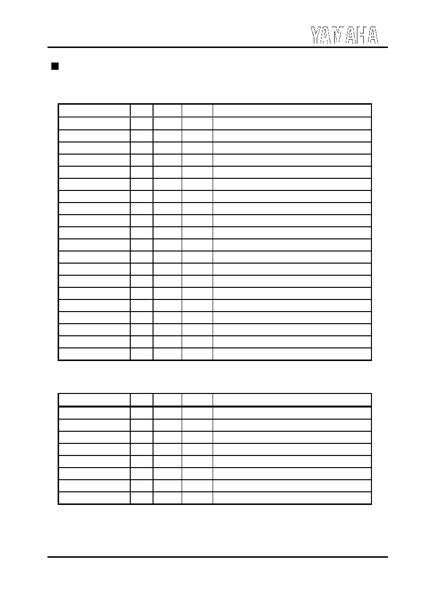
PIN DESCRIPTION
1. PCI Bus Interface (54-pin)
Name
I/O
Type
Size
Function
PCICLK
I
P
PCI Clock
RST#
I
P
Reset
AD[31:0]
IO
Ptr
Address / Data
C/BE[3:0]#
IO
Ptr
Command / Byte Enable
PAR
IO
Ptr
Parity
FRAME#
IO
Pstr
Frame
IRDY#
IO
Pstr
Initiator Ready
TRDY#
IO
Pstr
Target Ready
STOP#
IO
Pstr
Stop
IDSEL
I
P
ID Select
DEVSEL#
IO
Pstr
Device Select
REQ#
O
Ptr
PCI Request
GNT#
I
P
PCI Grant
PCREQ#
O
Ptr
PC/PCI Request
PCGNT#
I
P
PC/PCI Grant
PERR#
IO
Pstr
Parity Error
SERR#
O
Pod
System Error
INTA#
O
Pod
Interrupt signal output for PCI bus
SERIRQ#
IO
Ptr
Serialized IRQ
CLKRUN#
IO
Ptr
Clock Run
2. AC'97 Interface (8-pin)
Name
I/O
Type
Size
Function
CRST#
O
T
6mA
Reset signal for AC'97
CMCLK
O
C
6mA
Master Clock for AC'97 (24.576MHz)
CBCLK
I
T
-
AC-link: Bit Clock for AC'97 audio data
CSDO
O
T
6mA
AC-link: AC'97 Serial audio output data
CSYNC
O
T
6mA
AC-link: AC'97 Synchronized signal
CSDI0
I
T
-
AC-link: AC'97 Serial audio input data (Primary)
CSDI2
I
Tup
-
AC-link: AC'97 Serial audio input data (Secondary)
DOCKEN#
I
Tup
-
Docking Enable