YMU757B
MA-1C
YAMAHA CORPORATION
YMU757B CATALOG
CATALOG No.:LSI-4MU757B2
2000.4
Outline
The YMU75B is a high quality melody LSI for cellular phone handsets, supporting the data format for various
applications including ringing and holding melody sounds. The built-in Yamaha's original FM synthesizer can create
various timbres, and its built-in sequencer can produce up to 4 different sounds with 4 different timbres simultaneously
without placing a load to the controller.
The serial port controller interface enables real time reproduction of the melody data via FIFO, without the limitation of
the data capacity.
With a built-in amplifier to drive the dynamic type speaker, it is possible to connect the speaker directly.
This LSI also has an analog-output terminal for the phone jack. In the stand-by mode, the power consumption
can be reduced to 1
�
A or less while waiting.
Features
YAMAHA's original FM sound generator function
Built-in sequencer
Capable of producing up to 4 different sounds simultaneously (4 independent timbres available).
Built-in output 400mW speaker amplifier
Built-in circuit for sound quality correcting equalizer
Built-in serial interface
2.688, 8.4, 12.6, 14.4, 19.2, 19.68, 19.8 and 27.82 MHz serial clock inputs support
And support the mode which set to optional frequency from 2.685MHz to 27.853MHz at 55.93kHz intervals
Analog output for ear phone
Power down mode (Typ 1�A or less)
Power supply voltage (Digital and Analog): 3.0V�10 %
20-pin QFN

YMU757B
-2-
Contents
� General description of YMU757B....
.....................................................................3
� Block description........
....................................................................................4
� Pin configuration.....
.......................................................................................5
� Pin description....
..........................................................................................6
� Block diagram.....
..........................................................................................7
� Register map.......
..........................................................................................8
� Explanation of registers....
.................................................................................9-20
Musical score data...
..............................................................................9-13
Timbre data..........
..............................................................................14-17
Other control data.........
........................................................................17-20
� Power-down control division diagram......
...............................................................21
� Explanation of each bit........
..............................................................................21-23
� Resetting...................................................
......................................................24
� Settings & procedure required to generate melody..................
.......................................24
� Settings of clock frequency.............................................
.......................................24
� Interrupt sequence..............
..............................................................................25
� State transition description...........
........................................................................26-27
� Operation in FIFO empty state...
...........................................................................28
� Reproduction method assuming occurrence of empty state...
.............................................28
� Example of system connection...
...........................................................................29
� One sound and volume level adjustment in 4 sound pronunciation....
....................................30-31
� Sound quality correction circuit.
...........................................................................32-33
� Serial interface specifications....
...........................................................................34
� Electrical characteristics.......
..............................................................................35-40
� General description of FM sound generator....
............................................................41
� External dimensions........
.................................................................................42

YMU757B
-3-
General description of YMU757B
The YMU757B is controlled by way of the serial interface.
Shown below is its internal configuration.
When the data is inputted into the serial interface, it is converted into the parallel data and transmitted to each
function block according to the index address.
The musical score data is stored in the 32-word FIFO first and then transmitted to the sequencer where it is interpreted
and signals to control sound generation of the FM synthesizer is output.
The timbre register is where up to 8 timber data can be stored.
Also, as the sequencer controlling parameters, the start/stop and tempo signals are provided.
In order to have sound generated, the following processes must be performed for this LSI.
1) Initial status setting (cancellation of power-down function, clock selection, etc.)
2) Timbre data setting
3) Writing the musical score data in FIFO before starting the sequence
4) Writing the next musical score data before FIFO becomes empty upon receipt of the interrupt signal from
FIFO during reproduction,.
(For the details, refer to "Settings & procedure required to generate melody".)
Serial
interface
FIFO
32word
/IRQ
Sequencer
FM
Synthesizer
D/A +
Volume
AMP
Timbre
register
Musical score
data
Tempo
START/STOP
Timbre allotment
Timbre Data
Volume, power management, etc.
SDIN
SYNC
SCLK
SPOUT
HPOUT

YMU757B
-4-
Block description
1) Serial interface
When the serial interface receives the serial data, it identifies the index data and transmits the control data to each
function block.
2) FIFO
The musical score data are stored temporarily in FIFO which can contain up to 32 musical score data. The musical
score data are processed are processed in the sequencer when they are generated as sounds and those that have been
processed are deleted one after another. When the remaining data amount in FIFO reaches the register setting (IRQ
point) or less, it outputs an interrupt signal to ask for the continuing musical score data to be fed.
3) Sequencer
When the sequencer receives the START command, it starts to read the musical score data which have been stored in
FIFO. The processed musical score data are deleted.
4) Timbre register (Index 10h~2Fh)
The timbre data are stored in this register which can contain up to 8 timbres. Settings for this register must be made
before sound generation. Though it is initialized by hardware resetting, contents of a register aren't cleared, and the
value which had light last time is held as for the following.
� Software reset (CLR bit of Index32h)
� After the inside of the power going down mode and a release.
5) FM synthesizer
The timbres are synthesized and generated according to settings. Four sounds can be generated at the same time.
6) D/A, volume and amplifier
The outputs from the synthesizer are D/A converted and volume processed. After that, they are output from the
speaker or the earphone out terminal.
YMU757B
-5-
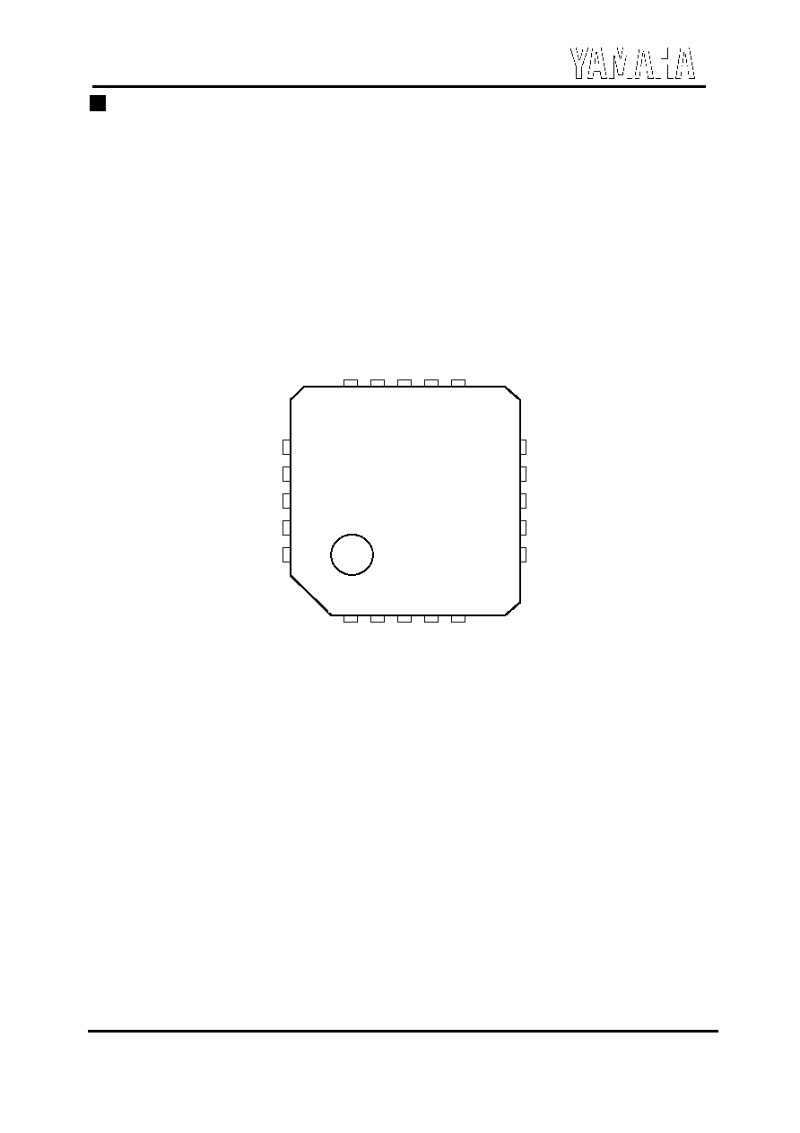
Pin configuration
20 Pin QFN Top View
SPVSS
AVDD
EQ3
EQ2
EQ1
SPO
U
T1
SPO
U
T2
D
V
SS
DVDD
/IRQ
1 2 3 4 5
15 14 13 12 11
10
9
8
7
6
16
17
18
19
20
/TESTI
/RST
TESTO
CLK_I
SDIN
HPO
U
T
VREF
AVSS
SCLK
SYN
C