
Features
∑
12 Fully Independent Correlation Channels
GPS
12-CHANNEL
CORRELATOR
POWER AND
RESET
CONTROL
MICRO_CLK
NRESET_O/P
A<22:20>
ARM60
INTERFACE
MEMORY
INTERFACE
ARM SYSTEM
ALE_I/P NCS WREN READ
STANDARD INTERFACE
MICROPROCESSOR INTERFACE
DUAL UART
REAL TIME CLOCK
WRPROG
NINTEL/ MOT
A<9:0>
NARMSYS
D<15:0>
SIGN, MAG
SAMPCLK
CLK_T, CLK_I
POWER_GOOD
PLL_LOCK
NRESET_I/P
ACCUM_INT
MEAS_INT
RXA
RXB
XIN
XOUT
TXA
TXB
DATA BUS
CONTROL BUS
Ordering Information
GP2021/IG/GQ1N (Trays)
GP2021/IG/GQ1Q (Tape and Reel)
∑
On-Chip Dual UART and Real Time Clock
∑
Compatible with most 16- and 32-bit Microprocessors
∑
Memory Control Logic for ARM60 Microprocessor
∑
Low Voltage, Low Current Power-Down Mode
∑
Power Dissipation 150mW Typical
∑
Compatible with GP2015 and GP2010 RF Front Ends
∑
Battery Backup Voltage 2.2V (min)
Applications
∑
GPS Navigation Systems
∑
GPS Geodetic Receivers
∑
Time Transfer Receivers
Related Global Positioning Products
Description
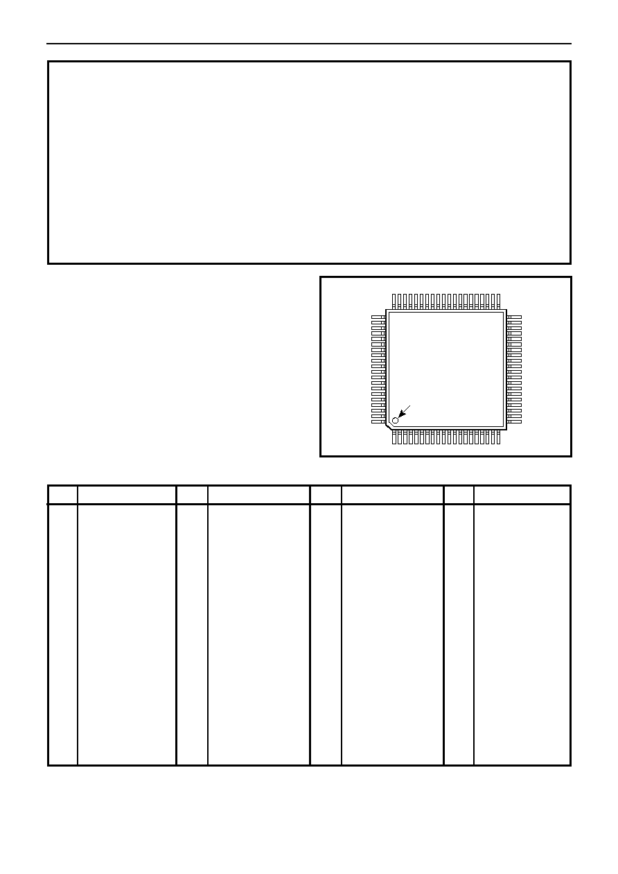
The GP2021 is a 12-channel C/A code baseband correlator
for use in NAVSTAR GPS satellite navigation receivers.
The GP2021 complements the GP2015 and GP2010 C/A
code RF downconverters available from Zarlink
Semiconductor.
The GP2021 is compatible with most 16-bit and 32-bit
microprocessors, especially those from Motorola and Intel,
with additional on-chip support for the ARM60 32-bit RISC
processor. When the ARM60 is used, the on-chip memory
management functions allow implementation of a full GPS
receiver with minimal external logic.
The GP2021 allows individual channel de-activation, for
systems not requiring full 12-channel operation, to save
power and processor loading. Receiver power may be
further conserved by reducing the supply voltage to 2.2V
under battery backup; all system functions are then
disabled but the 32.768kHz oscillator and Real Time Clock
are maintained for the microprocessor to estimate satellite
visibility at power-on to reduce signal acquisition time.
DS4077
Issue 3.2
April 2001
GP2021
GPS 12-Channel Correlator
Description
GPS receiver RF front end
(48-lead TQFP package)
GPS receiver RF front end
(44-lead PQFP package)
Data ref.
DS4374
DS4056
Part
GP2015
GP2010
32 bit RISC microprocessor
DS3553
P60ARM-B
App. Note
GPS ORION 12 Channel
GPS Receiver Reference
Design
AN4808
App. Note
GPS2000 GPS Receiver
Hardware Design
AN4855
2
GP2021
Pin
NRD/NC
ARM_ALE/NC
DBE/NC
ACCUM_INT
MEAS_INT
NBW/WRPROG
NMREQ/DISCIP2
NOPC/NINTELMOT
NRW/DISCIP3
MCLK/NC
ABORT MICRO_CLK
DISCIO
A22/READ
V
DD
V
SS
A21/NCS
A20/WREN
A9
A8
A7
Description
1
2
3
4
5
6
7
8
9
10
11
12
13
14
15
16
17
18
19
20
MULTI_FN_IO
POWER _GOOD
NRESET_OP
NARMSYS
XIN
XOUT
TXA
TXB
RXA
RXB
NROM/NC
NEEPROM/NC
NSPARE_CS/NC
V
DD
V
SS
NRAM/NC
NW0/NC
NW1/NC
NW2/NC
NW3/NC
Description
Pin
21
22
23
24
25
26
27
28
29
30
31
32
33
34
35
36
37
38
39
40
Pin
41
42
43
44
45
46
47
48
49
50
51
52
53
54
55
56
57
58
59
60
Description
A6
A5
A4
A3
A2
A1/ALE_IP
A0/NRESET_IP
D0
D1
D2
D3
D4
D5
D6
V
DD
V
SS
D7
D8
D9
D10
Pin
61
62
63
64
65
66
67
68
69
70
71
72
73
74
75
76
77
78
79
80
Description
D11
D12
D13
D14
D15
PLL_LOCK
V
DD
DISCOP
V
SS
CLK_T
CLK_I
V
SS
SAMPCLK
V
DD
NBRAM / DISCIP4
SIGN0
MAG0
SIGN1
MAG1
DISCIP1
Table 1 Pin assignments
Figure 2 Pin connections - top view
1
20
21
40
60
41
80
61
PIN 1 IDENT
GP2021
GQ80
Absolute Maximum Ratings
These are not the operating conditions, but are the absolute
limits which if exceeded, even momentarily, may cause
permanent damage. To ensure sustained correct operation
the device should be used within the limits given under
Electrical Characteristics. It is essential for both V
DD
and
V
SS
to be present before input signals are applied.
Page
3
4
7
7
8
11
11
12
12
14
15
15
21
Page
24
28
28
30
30
43
43
43
44
45
47
51
CONTENTS
TYPICAL GPS RECEIVER
PIN DESCRIPTION
FUNCTIONAL DESCRIPTION
12-Channel Correlator
Tracking Modules
PERIPHERAL FUNCTIONS
Dual UART
Real Time Clock (RTC) and Watchdog
Power and Reset Control
Discrete l/O
Digital System Test Interface
MICROPROCESSOR INTERFACE
SOFTWARE REQUIREMENTS
CONTROLLING THE GP2021
DETAILED DESCRIPTION OF REGISTERS
GP2021 Register Map
Correlator Registers
Tracking Channel Registers
Peripheral Functions Registers
Real Time Clock and Watchdog
DUART
SYSTEM CONTROL
GENERAL CONTROL
ELECTRICAL CHARACTERISTICS
TIMING CHARACTERISTICS
Supply voltage (V
DD
)
Input voltage (any input pin)
Output voltage (any output pin)
Storage temperature
V
SS
20∑3V to 16V
V
SS
20∑3V to V
DD
10∑3V
V
SS
20∑3V to V
DD
10∑3V
255
∞C to 1150∞C

3
GP2021
TYPICAL GPS RECEIVER
Fig. 3 shows a typical GPS receiver employing a GP2010
or GP2015 RF front end, a GP2021 correlator and an
ARM60 32-bit RISC microprocessor.
A single front end may be used, since all GPS satellites
use the same L1 frequency of 1575∑42 MHz. However, in
order to achieve better sky coverage, it is sometimes
desirable to use more than one antenna. In this case,
separate front ends will be required.
The RF section, GP2010 or GP2015, performs down
conversion of the L1 signal for digital baseband processing.
The resultant signal is then correlated in the GP2021 with
an internally generated replica of the satellite code to be
received. Individual codes for each channel may be
selected independently to enable acquisition and tracking
of up to 12 different satellites simultaneously. The results
of the correlations form the accumulated data and are
transferred to the microprocessor to give the broadcast
satellite data (the Navigation Message) and to control the
software signal tracking loops.
The GP2021 can be interfaced to one of two styles of front
end. In Real_lnput mode, the front end supplies either
a 1-bit (sign) or 2-bit (sign and magnitude) signal to either
the SIGN0/MAG0 or SIGN1/MAG1 inputs of the GP2021.
Alternatively, in Real_lnput mode, two separate front ends
can be connected to a single GP2021 and selected under
software control. The GP2015 and GP2010 are Real_lnput
mode front ends.
In Complex_lnput mode, the front end is required to supply
In-phase (I) and Quadrature (Q) signals to the SIGN0/
MAG0 and SIGN1/MAG1 inputs respectively. Hence, only
a single front end can be used with each GP2021 in
Complex_lnput mode. See Table 3, page 6.
Figure 3 Block diagram of a typical ARM-based receiver
GP2010/
GP2015
10MHz
TCXO
12-CHANNEL
CORRELATOR
SIGN
MAG
SAMPCLK
CLK_T
CLK_I
PLL_LOCK
L1 ANTENNA
WREN
READ
MICRO_CLK
PERIPHERAL
FUNCTIONS
ACCUM_INT, MEAS_INT
CONTROL
DATA
ADDR
MEMORY CONTROL
MEMORY
ARM60
TX/RX
SERIAL COMMS PORT
GP2021
4
GP2021
PIN DESCRIPTIONS
All V
SS
and V
DD
pins must be connected to their respective supplies in order to ensure reliable operation. Any unused
inputs must be tied high or low. Table 2 describes the pin functions in Real_lnput mode and assumes a master clock input
frequency of 40MHz. Those pins whose functions differ in Complex_lnput mode are described in Table 3.
Note that those pin names containing a forward slash (/) have dual functionality between ARM System and Standard
Interface modes. The pin mnemonic for ARM System mode always precedes the forward slash.
ARM system mode
15,35
56,69
72
14,34
55,67
74
1
2
3
4
5
6
7
8
9
10
11
12
13
16
17
18
19
20
21
22
23
V
SS
V
DD
MULTI_FN_IO
POWER _GOOD
NRESET_OP
NARMSYS
XIN
XOUT
TXA
TXB
RXA
RXB
NROM/NC
NEEPROM/NC
NSPARE_CS/NC
NRAM/NC
NW0/NC
NW1/NC
NW2/NC
NW3/NC
NRD/NC
ARM_ALE/NC
DBE/NC
Description
Pin
Signal name
Type
Standard interface mode
Ground pins
Power supply to device
2
1
I/O
I
O
I
I
O
O
O
I
I
O
O
O
O
O
O
O
O
O
O
O
Multi-function input / output. Its function is configured by the IO_CONFIG register.
After a GP2021 reset it acts as the Digital System Test Enable input. It can also be
configured as a discrete output, or a discrete input if certain conditions are met.
Can be configured as the TRIGGER
input to the DEBUG block
ROM Chip Select output (active low).
EEPROM Chip Select output (active low)
Spare Chip Select output (active low).
RAM Chip Select output (active low).
Byte 0 Write Strobe output (active low).
Byte 1 Write Strobe output (active low).
Byte 2 Write Strobe output (active low).
Byte 3 Write Strobe output (active low).
Read Data Strobe output (active low).
ALE output to the microprocessor (active
high). Controls the transparent latches at
the microprocessor address outputs.
Data Bus Enable output to the
microprocessor. When Low, places the
microprocessor data bus drivers in a high
impedance state.
Power Monitor input. High for normal operation. Low forces the GP2021 into
Power Down mode.
System Reset output (active low). Lasts for 4 MICRO_CLK cycles after all reset
conditions have cleared.
Processor Mode Selection input. When low, this input selects ARM System mode.
When high, standard Interface mode is selected.
Crystal input connection to Real Time Clock.
Crystal output connection from Real Time Clock.
Transmit Data output from Channel A of the dual UART.
Transmit Data output from Channel B of the dual UART.
Receive Data input to Channel A of the dual UART. This pin acts as a master
clock input in Digital System Test mode.
Receive Data input to Channel B of the dual UART. This pin acts as the Real Time
Clock reset in Digital System Test mode.
Unused output (do not connect)
Unused output (do not connect).
Unused output (do not connect).
Unused output (do not connect).
Unused output (do not connect.)
Unused output (do not connect).
Unused output (do not connect).
Unused output (do not connect).
Unused output (do not connect).
Unused output (do not connect).
Unused output (do not connect).
Table 2 Pin descriptions
cont...
5
GP2021
ARM system mode
24
25
26
27
28
29
30
31
32
33
36
37
38-45
46
47
ACCUM_INT
MEAS_INT
NBW/WRPROG
NMREQ/DISCIP2
NOPC/NINTELMOT
NRW/DISCIP3
MCLK/NC
ABORT/MICRO_CLK
DISCIO
A22/READ
A21/NCS
A20/WREN
A<9:2>
A1/ALE_IP
A0/NRESET_IP
Description
Pin
Signal name
Type
Standard interface mode
O
O
I
I
I
I
O
O
I/O
I
I
I
I
I
I
A free running interrupt to the microprocessor. It allows control of data transfer
between the accumulators in the correlator and the microprocessor. It is active
low when configured for ARM System mode or Motorola mode and is active high
in Intel mode.
An interrupt to the microprocessor. It allows control of measurement data transfer
between the correlator and the microprocessor. It is active Low when configured
for ARM System mode or Motorola mode and is active High in Intel mode.
Byte/Word input from the
microprocessor. Low indicates a byte
transfer, and high a word transfer.
Memory Request input from the
microprocessor. Low indicates that the
microprocessor requires a memory
access during the following cycle.
Opcode fetch input from the
microprocessor. Low indicates that an
instruction is being fetched and igh that
data is being transferred.
Read/Write Select input from the
microprocessor. Low indicates a read
cycle and high a write cycle.
Microprocessor Clock output (nominally
20MHz). Its phases can be stretched
under control of the Microprocessor
Interface.
Write-Read Program input. In Intel
mode, High selects 486 interface and
low 186 style. Unused in Motorola mode
Multi-purpose discrete input.
High selects Motorola mode and low
Intel mode.
Multi-purpose discrete input.
Unused output (do not connect).
Abort output to the microprocessor.
Generates a valid ARM Data Abort
sequence, triggered by a rising edge at
MULTI_FN_IO if this function is enabled.
20MHz Clock output. Provides a 20MHz
clock with a 1:1 mark-to-space ratio.
Multi-purpose discrete input/output. After a GP2021 reset it is configured as an
input.
Address input from the microprocessor.
A<22:20> are decoded to select the
address space partitioning.
Address input from the microprocessor.
A<22:20> are decoded to select the
address space partitioning.
Address input from the microprocessor
A<22:20> are decoded to select the
address space partitioning.
Read input from the microprocessor. In
Intel mode it is the active low read strobe.
In Motorola mode it is the Read (high)/
Write (low) select line.
GP2021 Chip Select input (active low).
Write-Read Strobe input from the
microprocessor. In Intel mode it is the
active low write strobe. In Motorola mode
it is the active high Write-Read strobe.
Address input 1 from the micro-
processor. A<1:0> are decoded to
provide individual byte write selection via
NW<3:0>.
Address input 0 from the micro-
processor. A<1:0> are decoded to
provide individual byte write selection via
NW<3:0>.
Address Inputs <9:2> from the microprocessor. These allow register selection.
Table 2 Pin descriptions (continued)
cont...
Address Latch Enable input from
microprocessor (active high)
Reset input (active low).