 | –≠–ª–µ–∫—Ç—Ä–æ–Ω–Ω—ã–π –∫–æ–º–ø–æ–Ω–µ–Ω—Ç: MEA224 | –°–∫–∞—á–∞—Ç—å:  PDF PDF  ZIP ZIP |

Obsolescence Notice
This product is obsolete.
This information is available for your
convenience only.
For more information on
Zarlink's obsolete products and
replacement product lists, please visit
http://products.zarlink.com/obsolete_products/

© 1997 Zarlink Semiconductor Inc.
Page:
1
Rev. 4.0 ≠December, 1997
P R E L I M I N A R Y D A T A S H E E T
EA-224
≠ 4-Port Fast Ethernet Access Controller
(XpressFlow
T M
2001 Series 10/100 Ethernet Switch Chipset)
1. DISTINCTIVE
CHARACTERISTICS
4 independent 10/100Mbps Ethernet Access Ports
Direct interface with 10BaseT transceiver
IEEE 802.3u compliant MII (Media Independent In-
terface) and Serial Management interface
Direct interface with 100BaseTX, -T2, -T4, or -TF
physical transceivers
State of the art 0.5 micron 3.3Volt CMOS process
352-PIN BGA package
Operating frequency
-33
33 MHz maximum
-40
40 MHz maximum
-50
50 MHz maximum
32-bit Local Buffer Memory Interface
Supports 128k to 1M bytes
Utilize high performance 32-bit Synchronous
Burst SRAM
Hardware assisted Buffer and Queue Management
to minimized CPU overhead
16-bit Processor Bus I/O Interface
Allows host to access Control Registers & Local
Buffer Memory
Supports Big and Little Endian CPUs
Direct interface with various different standard
microprocessors including 386, 486 families and
Motorola MPC series embedded processors.
32-bit XpressFlow Bus Interface
Uses Granule for frame transferring between
Access Controllers
Supports unicast, multicast, and broadcast frames
Also detects IEEE 802.3X MAC Control frames
Works together with SC-201 XpressFlow Engine
Capable to forward frames at full line-rate
Distributed Flow CachingTM to reduce frame for-
warding latency
Supports both Half & Full Duplex operation
Programmable Flow Control Enable
Jam Fake Collision for Half Duplex Mode
Transmit Flow Control Frame for IEEE 802.3x
Full Duplex Mode
Three frame forwarding modes
Store-&-Forward
Safe Cut-Thru (Runt Free)
Turbo Cut-Thru (10Mbps Mode only)
Automatically selects the optimized mode for
forwarding
Allows manual frame forwarding mode selection
override
Multi-Media ready with QoS supports
Four frame transmission priority queues
Complies with IEEE 802.1 Bridge Standard
Assigns one unique MAC Address for each port
VLAN ID Tagging & Stripping
Auto padding if necessary after stripping
Automatic retry frame transmission
Transmit collision
Transmit buffer under-run
Automatic receive filtering for bad frames for Store
& Forward Mode
Bad FCS
Short events or frames under 64 bytes
Long events or frames over 1518 bytes
Automatic statistic collection for RMON
LOCAL
BUFFER
MEMORY
Management BUS
XpressFlow BUS
16
32
32
EA-224
4-Port Ethernet
Access Controller
10/100M BaseTx Xceiver
Port
1
Port
3
Port
2
Port
0
10/100M BaseTx Ports

P
R
E
L
I
M
I
N
A
R
Y
D
A
T
A
S
H
E
E
T
XpressFlow-2001 Series ≠
EA-224
Ethernet Switch Chip-set
4-Port 10/100M Ethernet Access Controller
© 1997 Zarlink Semiconductor Inc. Page: 2
Rev. 4.0 ≠December, 1997
2. GENERAL DESCRIPTION:
The EA-224 provides four
10/100Mbps Ethernet network ac-
cess interface ports. MII interface
is used to connect external PHY
devices for 100 Mbps Ethernet.
They also can direct connect with
standard 10Mbps serial interface.
The EA-224 provides the Ethernet
MAC protocols, handles the local
buffer memory interface and
management, arbitrates among
multiple priority queues, and in-
terfaces with the
XpressFlow
En-
gine and other Access Controllers
through the
XpressFlow
message
passing protocol.
2.1 Related Components:
SC-201
≠ XpressFlow Engine
EA-208E
≠ 8-port 10Mbps
Ethernet Access Controller
EA-208
≠ 6-port 10 + 2-port
10/100 Ethernet Access Con-
troller
EA-222
≠ 2-port 10/100 Fast
Ethernet Access Controller
2.2 Typical Application:
A 16-port Ethernet Switch with
4 Fast Ethernet Up-Links
Local
Buffer
Memory
Management BUS
SWITCH BUS
Switch Bus
Interafce
MAC Port #0 to #3
Port 0
2
3
16
32
32
4-Port 100Base-Tx PHY
Managem
Bus Interafce
Local
Buffer
Memory
Interface
Automatic
Buffer
Manager
MAC Interface
1
Port 0
2
3
1
32
32
EA-224
Block Diagram ≠
EA-224 4-Port Ethernet Access Controller
Address
Mapping
Table
Flash
ROM
SC201
XpressFlow
Engine
EA208E
8-Port
Ethernet
Access
Controller
Management Bus
Buffer
RAM
Switch
Manager
CPU
DRAM
RS232 Local
Control Console
Buffer
RAM
8 Ethernet ports
Buffer
RAM
8 Ethernet ports
XpressFlow Bus
EA208E
8-Port
Ethernet
Access
Controller
Buffer
RAM
Four 100M
Fast Ethernet ports
EA224
4-Port
Ethernet
Access
Controller
System Block Diagram --
16-Port Ethernet Switch with 4 Fast Ethernet Up-Links
P
R
E
L
I
M
I
N
A
R
Y
D
A
T
A
S
H
E
E
T
XpressFlow-2001 Series ≠
EA-224
Ethernet Switch Chip-set
4-Port 10/100M Ethernet Access Controller
© 1997 Zarlink Semiconductor Inc. Page: 3
Rev. 4.0 ≠December, 1997
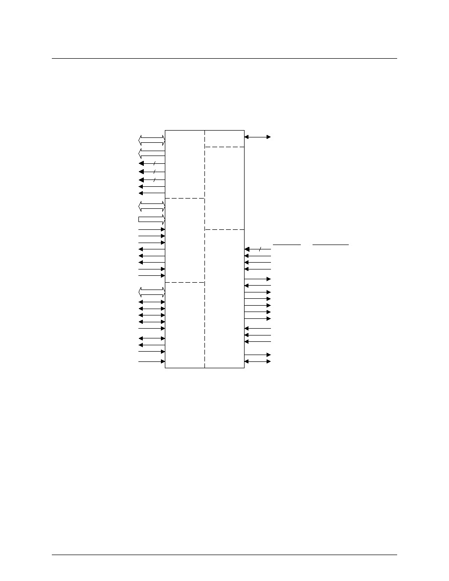
3. PIN ASSIGNMENT
3.1 Logic Symbol
EA-224
T _ M O D E
M _ M D C
M _ M D I O
XpressFlow
Bus Interface
Management Bus
Interface
Test Pin
P_D[15:0]
P _ C S #
P _ A D S #
P _ R W C
P _ B S 1 6 #
P _ R D Y #
P _ I N T
P _ R S T #
P _ C L K
P_A[11:1]
Control Buffer
Memory Interface
MII Serial
M a n a g e m ' t
M m _ R X D [ 3 : 0 ]
M m _ R X D V
M m _ R X C
M m _ R X E R
4
M m _ T X E R
M m _ T X C
M m _ T X E N
M m _ T X D [ 0 ]
M m _ T X D [ 1 ]
M m _ T X D [ 2 ]
M m _ T X D [ 3 ]
Port [3:0]
10/100 MII Interface
M m _ C O L
M m _ C R S
M m _ L N K
T m _ R X D
T m _ R X C
T m _ T X C
T m _ T X E N
T m _ T X D
T m _ L P B K
T m _ F D
T m _ C O L
T m _ C R S
T m _ L N K
M I I M o d e
1 0 B a s e T
Serial Xface
S_D[31:0]
S _ M S G E N #
S _ E O F #
S _ I R D Y
S _ T A B T #
S _ O V L D #
S _ H P R E Q #
S _ R E Q #
S _ G N T #
S _ C L K
L_D[31:0]
L_OE[3:0]#
L _ A D S C #
L _ C L K
L_A[18:2]
L _ W E [ 3 : 0 ] #
L _ B W E [ 3 : 0 ] #
4
4
4
P
R
E
L
I
M
I
N
A
R
Y
D
A
T
A
S
H
E
E
T
XpressFlow-2001 Series ≠
EA-224
Ethernet Switch Chip-set
4-Port 10/100M Ethernet Access Controller
© 1997 Zarlink Semiconductor Inc. Page: 4 Rev. 4.0 ≠December, 1997
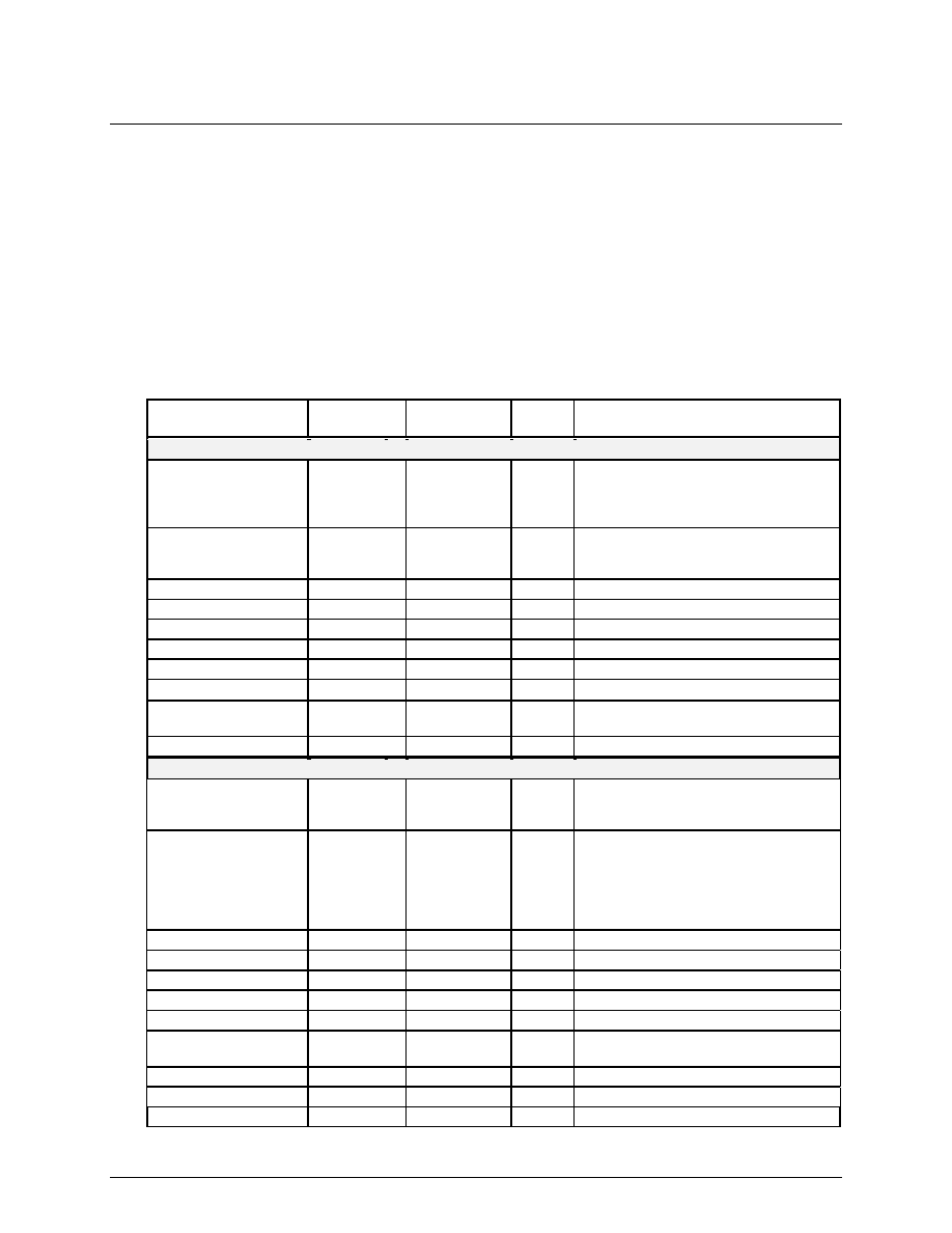
3.2 Pin Assignment (Preliminary)
Note:
#
Active low signal
Input
Input signal
I-ST
Input signal with Schmitt-Trigger
Output
Output signal (Tri-State driver)
Out-OD
Output signal with Open-Drain driver
I/O-TS
Input & Output signal with Tri-State driver
I/O-OD
Input & Output signal with Open-Drain driver
5VT
Input with 5V Tolerance
?
Output signal with programmable polarity.
@
Input or output pins with weak internal pull up resistors (50k to 100k Ohms each)
A
These pins are reserved for internal use only. They should be left unconnected.
Pin No(s).
Symbol
Type
Max
I
OL
/ I
OH
Name & Functions
Management Bus Interface
J25,K26,L24,K25,L26,
M24,L25,M26,N24,M25,
P24,N26,N25,R24,P26,
P25
P_D[15:0]
TTL I/O-TS
(5VT)
16mA
Management Bus ≠ Data Bit [15:0]
C26,D24,C25,E24,D26,
D25,F24,E26,E25,G24,
F26
P_A[11:1]
TTL In (5VT)
Management Bus ≠ Address Bit [11:1]
F25
P_ADS#
TTL In (5VT)
Management Bus ≠ Address Strobe
H25
P_RWC
TTL In (5VT)
Management Bus ≠ Read/Write Control
J24
P_RDY#
TTL Out-OD
16mA
Management Bus ≠ Data Ready
G25
P_BS16#
TTL Out-OD
16mA
Management Bus ≠ 16 bit Data Bus
G26
P_CS#
TTL In (5VT)
Management Bus ≠ Chip Select
H26
P_INT
?
CMOS Output
4mA
Management Bus ≠ Interrupt Request
J26
P_RST#
TTL In-ST
(5VT)
Management Bus ≠ Master Reset
K24
P_CLK
TTL In (5VT)
Management Bus ≠ Bus Clock
XpressFlow Bus Interface
C23,A23,B22,C22,A22
S_D[31:27] /
P_C[0:4]
CMOS I/O-TS
12 mA
XpressFlow Bus ≠ Data Bit [31:27] or
Management Bus Interface Configuration
bit [0:4]
B21,D20,C21,A21,B20,
A20,C20,B19,A19,C19,
B18,A18,B17,C18,A17,
D17,B16,C17,A16,B15,
A15,C16,B14,D15,A14,
C15,B13
S_D[26:0]
CMOS I/O-TS
12mA
XpressFlow Bus ≠ Data Bit [26:0]
B12
S_MSGEN#
CMOS I/O-TS
12 mA
XpressFlow Bus ≠ Message Envelope
A12
S_EOF#
CMOS I/O-TS
12mA
XpressFlow Bus ≠ End of Frame
C14
S_IRDY
CMOS I/O-TS
12 mA
XpressFlow Bus ≠ Initiator Ready
C13
S_TABT#
CMOS I/O-OD
12 mA
XpressFlow Bus ≠ Target Abort
B23
S_HPREQ#
CMOS I/O-OD
12mA
XpressFlow Bus ≠ High Priority Request
A24
S_REQ#
CMOS Output
4mA
XpressFlow Bus ≠ Bus Request to
SC201
B24
S_GNT#
CMOS Input
XpressFlow Bus ≠ Bus Grant from SC201
A13
S_OVLD#
CMOS Input
XpressFlow Bus ≠ Bus Overload
D13
S_CLK
CMOS Input
XpressFlow Bus ≠ Clock