 | –≠–ª–µ–∫—Ç—Ä–æ–Ω–Ω—ã–π –∫–æ–º–ø–æ–Ω–µ–Ω—Ç: MF272SMA | –°–∫–∞—á–∞—Ç—å:  PDF PDF  ZIP ZIP |
Document Outline
- Features
- Applications
- Description
- Figure 1 - Pin Diagram
- Figure 2 - Functional Schematic
- Optical and Electrical Characteristics - Case Temperature 25�C
- Absolute Maximum Ratings
- Thermal Characteristics
- Typical Fiber-Coupled Power
- Figure 3 - Relative Fiber-coupled Power vs. z - Axial Displacement of Fiber
- Figure 4 - Relative Fiber-Coupled Power vs. r - Radial Displacement of Fiber
- Figure 5 - Relative Fiber-coupled Power vs. Forward Current
- Figure 6 - Max. Electrical Power Dissipation vs. Operating Temperature
- Figure 7 - Forward Current vs. Forward Voltage
- Figure 8 - Peak Forward Current vs. Operating Temperature

1
Zarlink Semiconductor Inc.
Zarlink, ZL and the Zarlink Semiconductor logo are trademarks of Zarlink Semiconductor Inc.
Copyright 2001-2004, Zarlink Semiconductor Inc. All Rights Reserved.
Features
∑ 810 nm Surface-Emitting LED
∑ 70 MHz Bandwidth
∑ Designed for 200/280 µm fiber
Applications
∑ Avionics
∑ Sensors
∑ Military LANs
Description
This high speed device is optimized at 810 nm
wavelength which is of particular interest for use in
radiation-hardened fiber. It operates in a wide
temperature range and delivers very high power to
200 µm core fiber, making it ideal in avionics and
military datacom applications.
October 2004
Ordering Information
MF272
TO-46 Package
MF272 ST
ST Housing
MF272 SMA
SMA Housing
MF272 FC
FC Housing
-55
∞
C to +125
∞
C
Note: Rated Fiber coupled power apply only on the TO-46
package, for housing options fiber coupled power is
typically 10% less
MF272
810 nm - 70 MHz High Performance LED
Data Sheet
Figure 1 - Pin Diagram
Figure 2 - Functional Schematic
ANODE
CASE
Bottom View
CATHODE
Anode in electrical contact with the case
ANODE
CATHODE

MF272
Data Sheet
2
Zarlink Semiconductor Inc.
Note 1: Measured at the exit of 100 meters of fiber.
Optical and Electrical Characteristics - Case Temperature 25
∞
C
Parameter
Symbol
Min.
Typ.
Max.
Unit
Test Condition
Fiber-Coupled Power
(Figures 3, 4, and 5) (Table 1)
P
fiber
1300
1600
µW
I
F
= 100 mA
(Note 1)
Fiber:
200/280
µm
Step
Index
Rise and Fall Time (10-90%)
t
r
,t
f
7
10
ns
I
F
= 100 mA
(no bias)
Bandwidth (3 dB
el
)
f
c
70
MHz
I
F
= 100 mA
Peak Wavelength
p
790
810
830
nm
I
F
= 100 mA
Spectral Width (FWHM)
50
nm
I
F
= 100 mA
Forward Voltage (Figure 7)
V
F
2.2
2.4
V
I
F
= 100 mA
Reverse Current
I
R
20
µA
V
R
= 1 V
Capacitance
C
250
pF
V
R
-0V, f = 1 MHz
Absolute Maximum Ratings
Parameter
Symbol
Limit
Storage Temperature
T
stg
-55 to +125
∞
C
Operating Temperature (derating: Figure 6)
T
op
-55 to +125
∞
C
Electrical Power Dissipation (derating: Figure 6)
P
tot
250 mW
Continuous Forward Current (f<10 kHz)
I
F
110 mA
Peak Forward Current (duty cycle<50%,f>1 MHz
I
FRM
180 mA
Reverse Voltage
V
R
1.5 V
Soldering Temperature (2 mm from the case for 10 sec.)
T
sld
260
∞
C
Thermal Characteristics
Parameter
Symbol
Min.
Typ.
Max.
Unit
Thermal Resistance - Infinite Heat Sink
R
thjc
100
∞
C/W
Thermal Resistance - No Heat Sink
R
thja
400
∞
C/W
Temperature Coefficient - Optical Power
dP/dT
j
-0.4
%/
∞
C
Temperature Coefficient - Wavelength
d
/dT
j
0.3
nm/
∞
C
Typical Fiber-Coupled Power
Core Diameter/Cladding Diameter Numerical Aperture
50/125
µm
0.20
62.5/125
µm
0.275
100/140
µm
0.29
200/230
µm
0.37
200/280
µm
0.24
60
µW
150
µW
600
µW
2000
µW
1600
µW
MF272
Data Sheet
3
Zarlink Semiconductor Inc.
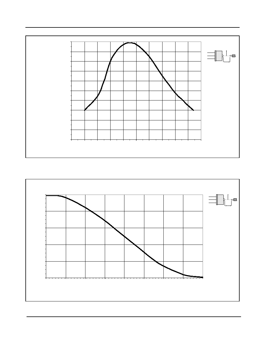
Figure 3 - Relative Fiber-coupled Power vs. z - Axial Displacement of Fiber
Figure 4 - Relative Fiber-Coupled Power vs. r - Radial Displacement of Fiber
0
10
20
30
40
50
60
70
80
90
100
0.5
0.75
1
1.25
1.5
1.75
2
2.25
2.5
2.75
3
z - Axial Displacem ent of Fiber (m m )
Relative Fiber
-
Coupled Power
(%)
z
r
r - optimal
ÿ
C
= 200
µm
(
µm)
0
20
40
60
80
100
0
25
50
75
100
125
150
175
200
r - Radial Displacem ent of Fiber (
µm)
Rel
a
ti
ve Fi
ber
-
Coupl
ed Power
(%)
z
r
z - optimal
ÿ
C
= 200
µm
MF272
Data Sheet
4
Zarlink Semiconductor Inc.
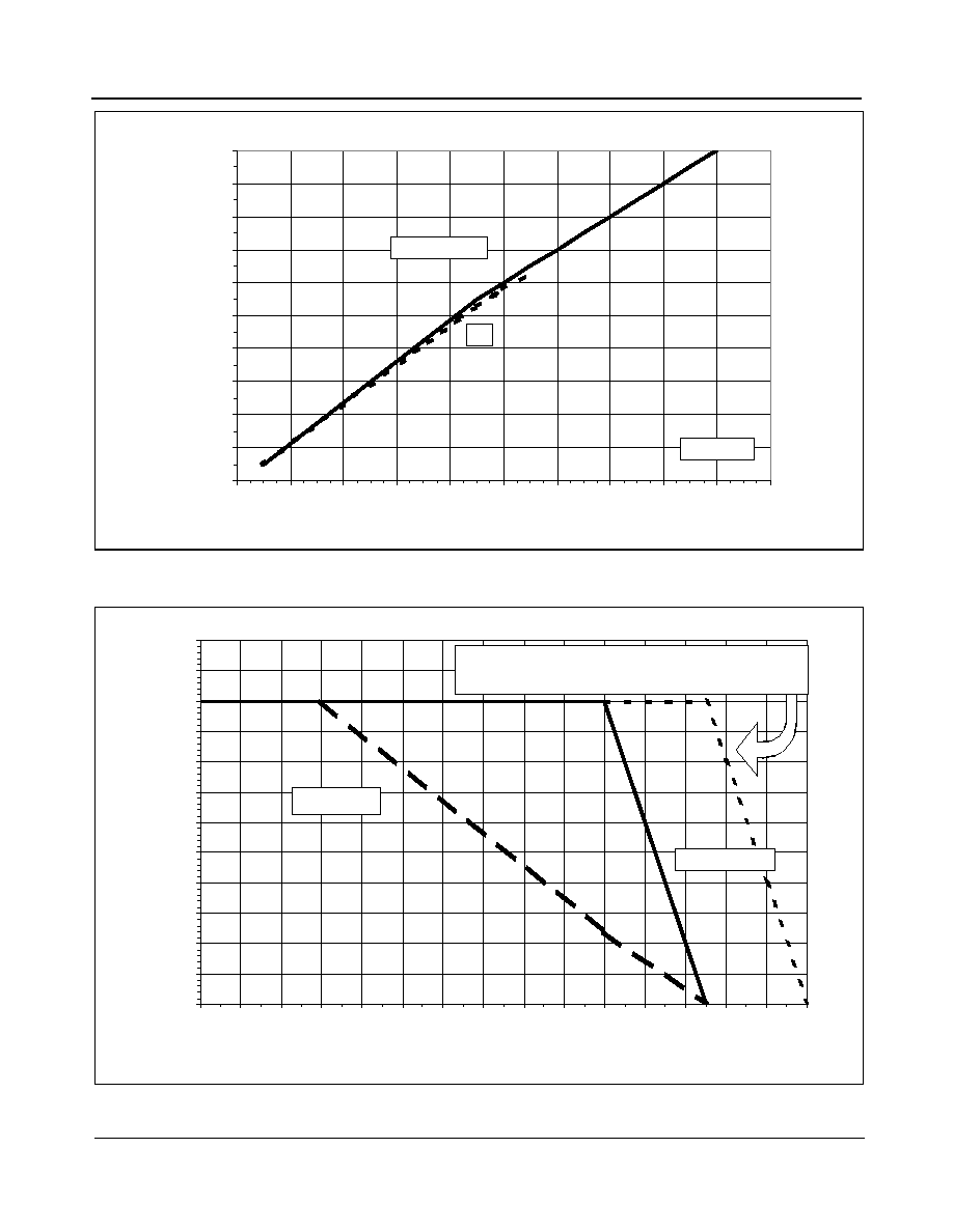
Figure 5 - Relative Fiber-coupled Power vs. Forward Current
Figure 6 - Max. Electrical Power Dissipation vs. Operating Temperature
0
10
20
30
40
50
60
70
80
90
100
0
20
40
60
80
100
120
140
160
180
200
Forw ard Current (mA)
Relative Fiber-Coupled Power (%)
50% Duty Cycle
Heat Sinked
DC
0
25
50
75
100
125
150
175
200
225
250
275
300
0
10
20
30
40
50
60
70
80
90
100
110
120
130
140
150
Operating Temperature (
O
C)
Max. Elect
rical Power Dissipat
i
on (
m
W)
No Heat Sink
Infinite Heat Sink
Note: Maximum junction temperature can be increased to
150
o
C after additional burn-in and screening.
MF272
Data Sheet
5
Zarlink Semiconductor Inc.
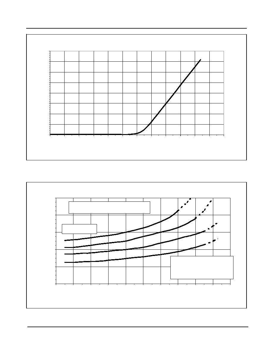
Figure 7 - Forward Current vs. Forward Voltage
Figure 8 - Peak Forward Current vs. Operating Temperature
0
25
50
75
100
125
150
175
200
0
0.25
0.5
0.75
1
1.25
1.5
1.75
2
2.25
2.5
2.75
3
Forw ard Voltage (V)
Forward Current (mA)
0
40
80
120
160
200
-60
-40
-20
0
20
40
60
80
100
120
140
Operating Tem perature (
O
C)
Peak Forward Current (mA)
a
b
c
d
a) P fiber = const. 1450 W peak
b) P fiber = const. 1200 W peak
c) P fiber = const. 950 W peak
d) P fiber = const. 700 W peak
Note: Dashed line indicates that the pow er
dissipation may exceed the maximum ratings.
Heat Sinked
µ
µ
µ
µ