1
Zarlink Semiconductor Inc.
Zarlink, ZL and the Zarlink Semiconductor logo are trademarks of Zarlink Semiconductor Inc.
Copyright 2003, Zarlink Semiconductor Inc. All Rights Reserved.
Features
∑ 780nm Surface-Emitting LED
∑ 55MHz Bandwidth
∑ Designed for 62.5/125µm fiber
∑ Low thermal droop
Applications
∑ Baseband Video
∑ Sensors
∑ General Purpose
Description
The low thermal droop of this device allows baseband
video transmission with minimum distortion. The
double-lens optical system provides for optimum
coupling of power into the fiber. It matches with the
MF446 PIN Photodiode.
August 2003
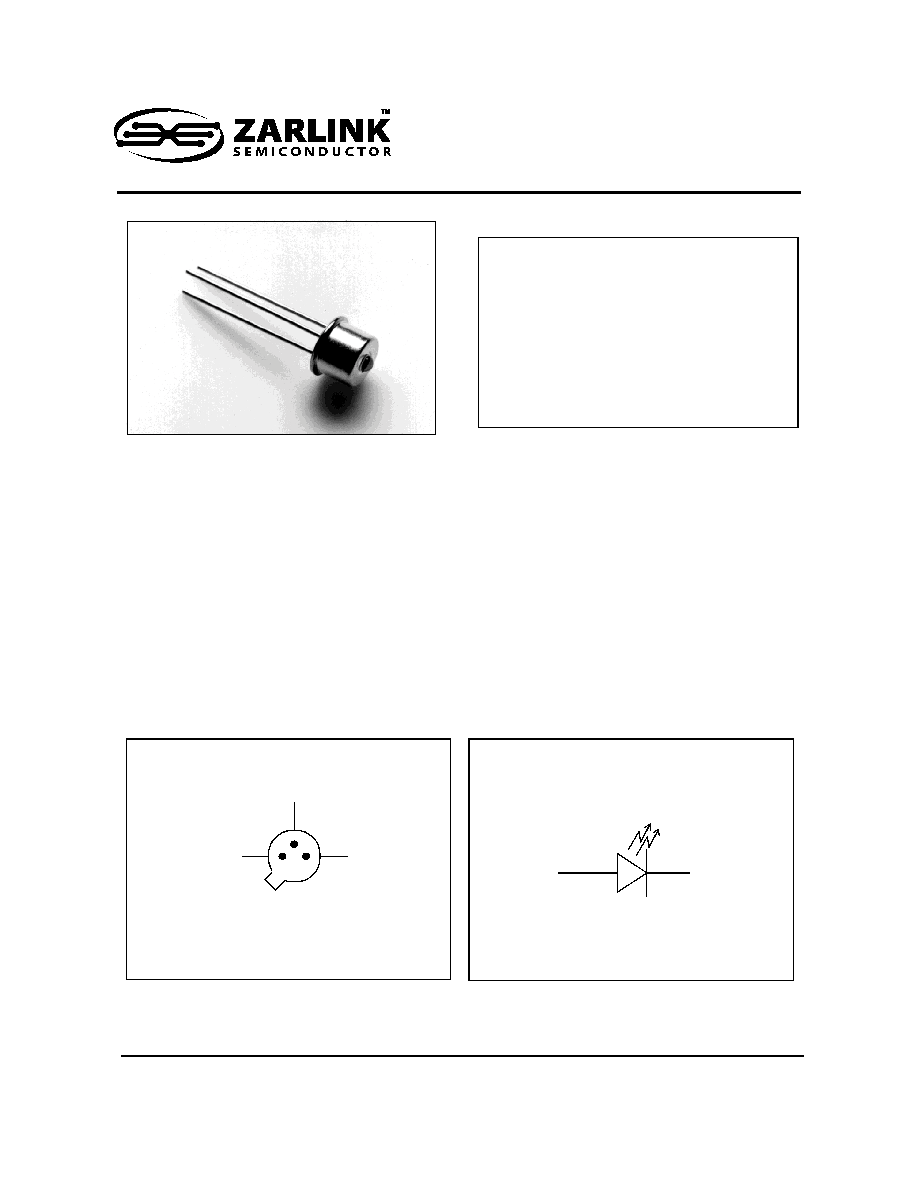
MF359
780nm - 55MHz High Performance LED
Data Sheet
Ordering Information
MF359
TO-46 Package
MF359 ST
ST Housing
MF359 SMA
SMA Housing
-40
∞
C to +85
∞
C
Note: Rated Fiber coupled power apply only on the TO-46
package, for housing options fiber coupled power is
typically 10% less.
Figure 1 - Pin Diagram
Figure 2 - Functional Schematic
CATHODE
CASE
Bottom View
ANODE
ANODE
CATHODE
MF359
Data Sheet
2
Zarlink Semiconductor Inc.
Note 1: Measured at the exit of 100 meters of fiber.
Note 2: Transient decline in optical power due to self-heating.
Optical and Electrical Characteristics - Case Temperature 25
∞
C
Parameter
Symbol
Min
Typ
Max
Unit
Test Condition
Fiber-Coupled Power
P
fiber
80
120
µ
W
I
F
=80mA
(Note 1)
Fiber:
62.5/
125
µ
m
Graded
Index
NA=0.275
Rise and Fall Time (10-90%)
t
r
,t
f
6
8
ns
I
F
=80mA
(no bias)
Bandwidth (3dB
el
)
f
c
55
MHz
I
F
=80mA
Thermal Droop
(non linearity) (Note 2)
I
PI
2
%
I
F
=80mA
Peak Wavelength
p
760
780
800
nm
I
F
=80mA
Spectral Width (FWHM)
50
nm
I
F
=80mA
Forward Voltage (Figure 7)
V
F
2.2
2.6
V
I
F
=80mA
Reverse Current
I
R
20
µ
A
V
R
=1V
Capacitance
C
250
pF
V
R
-0V, f=1MHz
Absolute Maximum Ratings
Parameter
Symbol
Limit
Storage Temperature
T
stg
-55 to +125
∞
C
Operating Temperature (derating: Figure 6)
T
op
-40 to +85
∞
C
Electrical Power Dissipation (derating: Figure 6)
P
tot
300 mW
Continuous Forward Current (f<10kHz)
I
F
110 mA
Peak Forward Current (duty cycle<50%,f>1MHz
I
FRM
180 mA
Reverse Voltage
V
R
1.5 V
Soldering Temperature (2mm from the case for 10 sec.)
T
sld
260
∞
C
Thermal Characteristics
Parameter
Symbol
Min
Typ
Max
Unit
Thermal Resistance - Infinite Heat Sink
R
thjc
100
∞
C/W
Thermal Resistance - No Heat Sink
R
thja
400
∞
C/W
Temperature Coefficient - Optical Power
dP/dT
j
-0.5
%/
∞
C
Temperature Coefficient - Wavelength
d
/dT
j
0.3
nm/
∞
C
MF359
Data Sheet
3
Zarlink Semiconductor Inc.
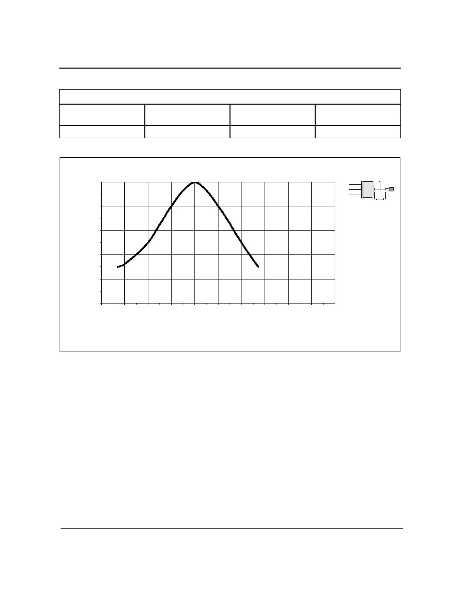
Figure 3 - Relative Fiber-coupled Power vs. z - Axial Displacement of Fiber
Typical Fiber-Coupled Power
Core Diameter/Cladding Diameter Numerical Aperture
50/125
µ
m
0.20
62.5/125
µ
m
0.275
100/140
µ
m
0.29
200/230
µ
m
0.37
60
µ
W
120
µ
W
250
µ
W
400
µ
W
0
20
40
60
80
100
0.5
0.75
1
1.25
1.5
1.75
2
2.25
2.5
2.75
3
z - Axial Displacem ent of Fiber (m m )
Re
l
a
ti
v
e
Fi
be
r-c
oupl
e
d
P
o
w
e
r (%)
z
r
r - optimal
ÿ
C
= 62.5
µ
m
MF359
Data Sheet
4
Zarlink Semiconductor Inc.
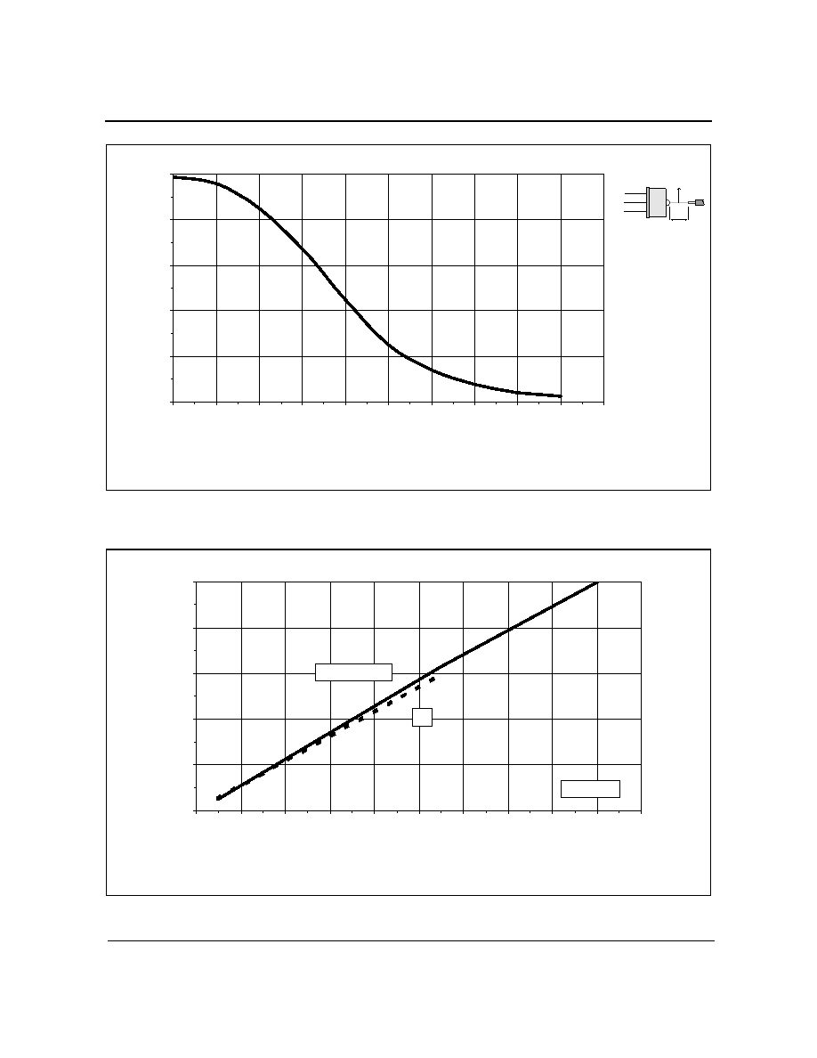
Figure 4 - Relative Fiber-coupled Power vs. r - Radial Displacement of Fiber
Figure 5 - Relative Fiber-coupled Power vs. Forward Current
z
r
z - optimal
ÿ
C
= 62.5
µ
m
0
20
40
60
80
100
0
10
20
30
40
50
60
70
80
90
100
r - Radial Displacem ent of Fiber (
µ
µ
µ
µ
m )
Re
l
a
ti
v
e
Fi
be
r-c
oupl
e
d
P
o
w
e
r (%)
0
20
40
60
80
100
0
20
40
60
80
100
120
140
160
180
200
Forw ard Current (mA)
Re
l
a
ti
v
e
Fi
be
r
-
c
oupl
e
d
P
o
we
r
(%)
50% Duty Cycle
DC
Heat Sinked
MF359
Data Sheet
5
Zarlink Semiconductor Inc.
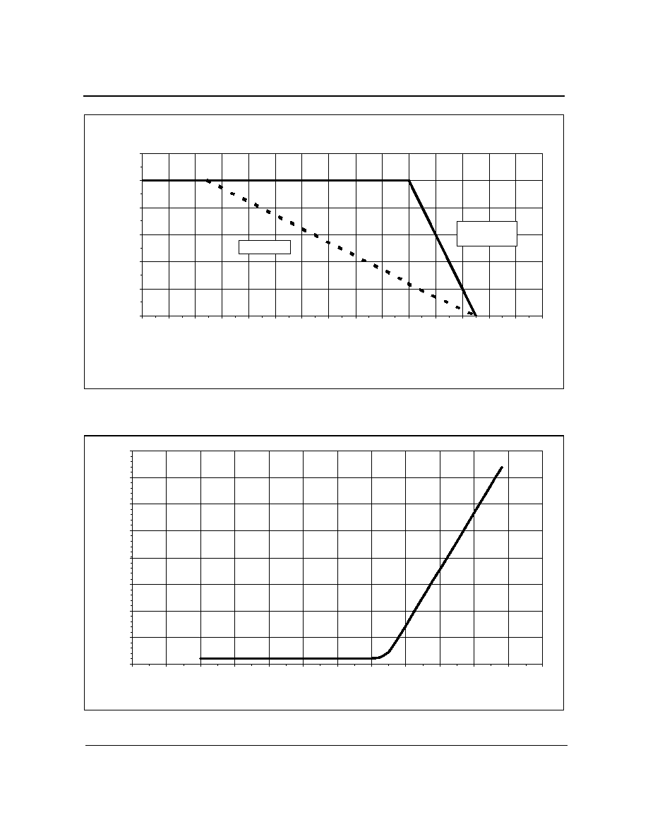
Figure 6 - Max. Electrical Power Dissipation vs. Operating Temperature
Figure 7 - Forward Current vs. Forward Voltage
0
50
100
150
200
250
300
0
10
20
30
40
50
60
70
80
90
100
110
120
130
140
150
Operating Tem perature (
o
C)
M
ax.
El
ectr
i
cal
Po
wer
D
i
ssi
p
a
ti
o
n
(mW
)
No Heat Sink
Infinite
Heat Sink
0
25
50
75
100
125
150
175
200
0
0.25
0.5
0.75
1
1.25
1.5
1.75
2
2.25
2.5
2.75
3
Forw ard Voltage (V)
F
o
r
ward
C
u
rren
t
(
m
A
)