
2-287
�
zFeatures
�
Loop Start Trunk Interface
�
900
Input Impedance
�
2-4 Wire Conversion
�
On-Hook Reception
�
Line State Detection Outputs:
- Forward Loop
- Reverse Loop
- Switch Hook
- Ringing Voltage
�
Relay Driver
�
Industrial Temperature Range option
�
DIL and SMT versions
�
Meets FCC part 68 Leakage Current
Requirements
Applications
Interface to Central Office for:
�
PABX
�
Key Telephone Systems
�
Channel Bank
�
Voice Mail
�
Terminal Equipment
�
Digital Loop Carrier
�
Optical Multiplexer
Description
The Mitel MH88636-4 Central Office Trunk Interface
circuit provides a complete analog and signalling link
between audio switching equipment and a subscriber
Line.
The device is fabricated as a thick film hybrid
technology for optimum circuit design and very high
reliability for both commercial and industrial
temperature changes.
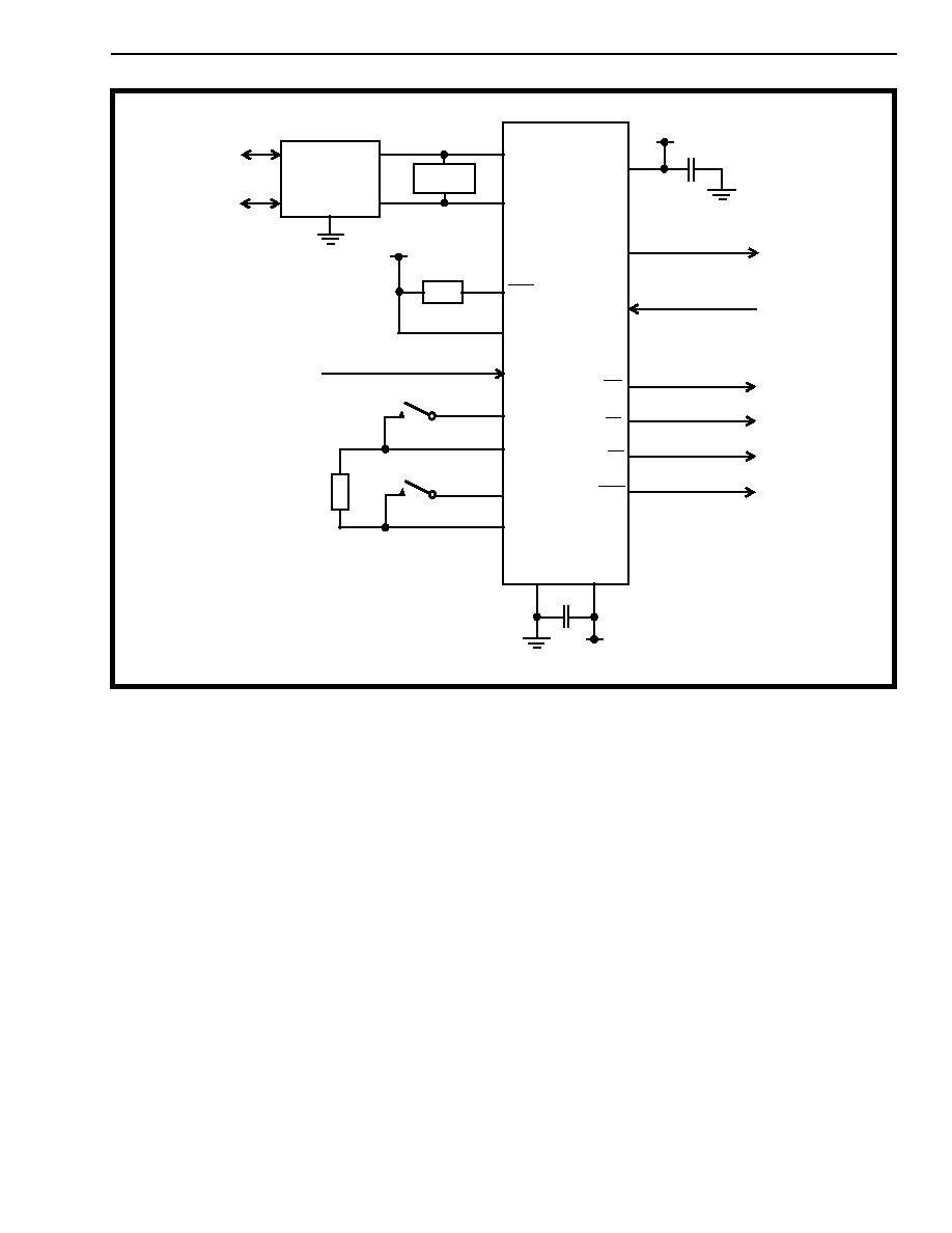
Figure 1 - Functional Block Diagram
Status
Detection
Receive
Gain
Transmit
Gain
2 - 4 Wire
Hybrid
Line
Termination
Loop Relay
Driver
Network
Balance
XLA XLB XLC XLD
LRC
LRD
VRLY
TIP
RV
VCC
RX
TX
VEE
AGND
FL
RL
SHK
RING
&
Impedance
Matching
ISSUE 2
January 1997
Ordering Information
MH88636AD-4I
28 Pin DIL Package
-40
�
C to 85
�
C
MH88636AD-4
28 Pin DIL Package
MH88636AS-4
28 Pin SMT Package
0
�
C to 70
�
C
MH88636-4
Central Office Interface Circuit
Preliminary Information

MH88636-4
Preliminary Information
2-288
Figure 2 - Pin Connections
Pin Description
Pin #
Name
Description
1
XLB
Loop Relay Contact B. Connects to XLA through the Loop Relay contacts (K1) when the
relay is activated.
2
XLC
Loop Relay Contact C. Connects to XLD through the Loop Relay contacts (K1) when the
relay is activated.
3
IC
Internal Connection. No connection should be made to this pin.
4
TIP
Tip lead. Connects to the Tip lead of a Telephone Line.
5
RING
Ring Lead. Connects to the Ring lead of a Telephone Line.
6 - 11
IC
Internal Connection. No connection should be made to this pin.
12
RL
Reverse Loop detect. In the on-hook status, a logic 0 output indicates that reverse loop
battery is present. In the off-hook state, a logic 0 output indicates that reverse loop current
is present.
13
FL
Forward Loop Detect. In the on-hook status, a logic 0 output indicates that forward loop
battery is present. In the off-hook state, a logic 0 output indicates that forward loop current
is present.
14
RV
Ringing Voltage Detect (Output). A logic 0 indicates that ringing voltage is across the Tip
and Ring leads.
15, 16,
19
IC
Internal Connection. No connection should be made to this pin.
17
TX
Transmit (Output). 4 Wire ground (AGND) referenced analog output.
18
RX
Receive (Input). 4 Wire ground (AGND) referenced analog input.
20
SHK
Switch Hook (Output). A logic 0 indicates the presence of forward or reverse battery
when LRC is logic 0 and the presence of forward or reverse loop current when LRC is logic
1.
21
LRC
Loop Relay Control (Input). A logic 1 activates the Loop Relay Driver output (LRD).
22
VEE
Negative Power Supply. -5V DC
23
AGND
Analogue Ground. 4 Wire ground. Normally connected to System Ground.
24
VCC
Positive Power Supply. +5V DC
25
VRLY
Relay Supply Voltage. Typically +5V. Connects to the relay supply voltage.
XLB
XLC
IC
TIP
RING
IC
IC
IC
IC
RV
FL
RL
IC
IC
XLD
XLA
LRD
VRLY
VCC
AGND
VEE
LRC
SHK
IC
RX
TX
IC
IC
1
2
3
4
5
6
7
8
9
10
11
12
13
14
15
16
17
18
19
20
21
22
23
24
25
26
27
28

Preliminary Information
MH88636-4
2-289
Functional Description
The MH88636-4 is a Central Office Interface Circuit
(COIC). It is used to correctly terminate a Central
Office 2-Wire telephone line. The device provides a
signalling link and a 2-4 Wire line interface between
the telephone line and subscriber equipment. The
subscriber equipment can include Private Branch
Exchanges (PBX's), Key Telephone Systems,
Terminal Equipment, Digital Loop Carriers and
Wireless Local Loops.
All descriptions assume that the device is connected
as in the application circuit shown in Figure 3.
Isolation Barrier
The MH88636-4 provides an isolation barrier which
is designed to meet FCC Part 68 (November 1987)
Leakage Current Requirements.
External Protection Circuit
An external Protection Circuit assists in preventing
damage to the device and the subscriber equipment,
due to over-voltage conditions. The type of
protection required is dependant upon the
application and regulatorary standards. In Figure 3
the protection is shown in block form. Further details
should be obtained from the specific country's
regulatorary body.
Suitable Markets
The MH88636-4 has a selectable Input Impedance
of 900
or 900
+ 2.16
�
F. This makes it suitable
primarily for North America or Brazilian markets.
Line Termination
When LRC is at a logic 1,
LRD will sink current
which energizes the Loop Relay (K1), connecting
XLA to XLB and XLC to XLD. This places a line
termination across Tip and Ring. The device can be
considered to be in an off-hook state and DC loop
current will flow. The line termination consists of a
DC resistance and an AC impedance.
When LRC is at a logic 0, the Line Termination is
removed from across Tip and Ring. An external
Dummy Ringer should be permanently connected
across Tip and Ring and under these conditions is
the only load on the line. The device can be
considered to be in an on-hook state and negligible
DC current will flow. The Dummy Ringer is a series
AC load of typically (17k
+330nF) which represents
a mechanical telephone ringer and allows ringing
voltages to be sensed. This load can be considered
negligible when the line has been terminated.
Depending on the Network Protocol being used the
line termination can seize the line for an outgoing
call, terminate an incoming call, or if applied and
disconnected at the correct rate can be used to
generate dial pulse signals.
The DC line termination circuitry provides the line
with an active DC load which is equivalent to a DC
resistance of less than 300
,
dependant upon the
loop current.
Ringing Equivalent Number
The Ringing Equivalent Number (REN) is application
specific. See the governing regulatory body
specification for details.
AC Input Impedance
The Input Impedance (Zin) is the AC impedance that
the MH88636-4 places across Tip and Ring in order
to terminate the telephone line. It can be set to
either 900
or 900
+ 2.16uF by connecting an
external impedance between XLA and XLD (Zext).
To select a 900
Input Impedance, 1000
must be
connected across XLA and XLD.
26
LRD
Loop Relay Drive (Output). Connects to the Loop Relay coil. When LRC is at a logic 1 an
open collector output at LRD sinks current and energizes the relay.
27
XLA
Loop Relay Contact A. Connects to XLB through the Loop Relay (K1) contacts when the
relay is activated.
28
XLD
Loop Relay Contact D. Connects to XLC through the Loop Relay (K1) contacts when the
relay is activated.
Pin Description (continued)

MH88636-4
Preliminary Information
2-290
To select a 900
+ 2.16
�
F Input Impedance, 1000
+ 360
//2.2uF must be connected across XLA and
XLD.
All connections should be kept as short as possible.
Network Balance Impedance
The MH88636-4's Network Balance Impedance has
been optimised for either of the two Input
Impedances.
2-4 Wire Conversion
The device converts the balanced 2-Wire input,
presented by the line at Tip and Ring, to a ground
referenced signal at TX. This circuit operates with or
without loop current; signal reception with no loop
current is required for on-hook reception enabling the
detection of Caller Line Identification (CLI) signals.
Conversely the device converts the ground
referenced signal input at RX, to a balanced 2-Wire
signal across Tip and Ring.
The 4-Wire side (TX and RX) can be interfaced to a
filter/codec, such as the Mitel MT896X, for use in
digital voice switched systems
During full duplex transmission, the signal at Tip and
Ring consists of both the signal from the device to
the line and the signal from the line to the device.
The signal input at RX, being sent to the line, must
not appear at the output TX. In order to prevent this,
the device has an internal cancellation circuit. The
measure of attenuation is Transhybrid Loss (THL).
Transmit and Receive Gain
The Transmit Gain of the device is the gain from the
balanced signal across Tip and Ring to the ground
referenced signal at TX. It is set at 0dB.
The Receive Gain of the device is the gain from the
ground referenced signal at RX to the balanced
signal across Tip and Ring. It is set at -2dB.
Supervision Features
Line Status Detection Outputs
The MH88636-4 supervisory circuitry provides the
signalling status outputs which are monitored by the
system controller. The supervisory circuitry is
capable of detecting: Ringing Voltage; Forward and
Reverse loop battery; Forward and Reverse loop
current; and Switch Hook.
�
Ringing Voltage Detect Output (RV)
The RV output provides a logic 0 when ringing
voltage is detected across Tip and Ring. It toggles at
the ringing frequency, typically going low 50ms after
the ringing voltage is applied and remains low for 50
ms after ringing voltage is removed.
�
Forward Loop and Reverse Loop Detect
Outputs (FL & RL)
The FL output provides a logic 0 when either forward
loop battery or forward loop current is detected, that
is the Ring pin voltage is negative with respect to Tip
pin voltage.
The RL output provides a logic 0 when either reverse
loop battery or reverse loop current is detected, that
is the Tip pin voltage is negative with respect to Ring
pin voltage.
�
The Switch Hook Detect (SHK)
The SHK output is active if either forward loop or
reverse loop current is detected, or if forward or
reverse battery voltage is detected.
Control InputS
The MH88636-4 accepts a control signal from the
system controller at the Loop Relay Control input
(LRC). This energises the relay drive output Loop
Relay Drive (LRD). The output is active low and has
an internal clamp diode to VRLY.
The intended use of this relay driver is to add and
remove the Line Termination from across Tip and
Ring, as shown in Figure 3.
If this Control input and the Supervisory Features are
used as indicated in Figure 3, Loop-Start Signalling
can be implemented.
Mechanical Data
See Figure 9 and 10 for details of the mechanical
specification.
Preliminary Information
MH88636-4
2-291
Figure 3 - Typical LS Application Circuit
MH88636-4
Analog Out
Analog In
Ringing Detect
Forward Loop
Reverse Loop
Switch Hook
-5V
+5V
K1
Protection
Circuit
Tip
Ring
Loop Relay Control
TIP
RING
LRD
VRLY
LRC
XLA
XLB
XLC
XLD
VCC
AGND
VEE
SHK
RL
FL
RV
RX
TX
K1
NOTES:
1) K1 Electro Mechanical 2 Form A
K1
Dummy
2) Dummy Ringer is typically 17k
+ 330nF
Zext
Ringer
C1
C2
3) C1 and C2 are decoupling capacitors
1
27
13
12
2
20
28
23
22
14
21
26
5
25
18
17
24
4
+5V