 | –≠–ª–µ–∫—Ç—Ä–æ–Ω–Ω—ã–π –∫–æ–º–ø–æ–Ω–µ–Ω—Ç: MSC201AL | –°–∫–∞—á–∞—Ç—å:  PDF PDF  ZIP ZIP |

©
1997
9
(57(;
1
(7:25.6
Page:
1
Rev. 4.1 ≠ December, 1997
P R E L I M I N A R Y D A T A S H E E T
SC-201 ≠
XpressFlow Engine
(XpressFlowTM 2001 Series 10/100 Ethernet Switch Chipset)
1. DISTINCTIVE
CHARACTERISTICS
Highly integrated central switch controller
State of the art 0.5 micron 3.3 Volt CMOS
process
256-PIN PQFP package
Operating frequency
-33
33MHz
maximum
-40
40
MHz
maximum
-50
50
MHz
maximum
16-bit external CAM interface
Supports Ωk to 8k MAC addresses
32-bit Control Buffer Memory interface
Supports 128k to 1M bytes
Utilize high performance 32-bit Syn-
chronous Burst SRAM
Hardware assisted Buffer and Queue
Management to minimized CPU overhead
32-bit Management Bus I/O interface
Allows host to access CAM and Control
Buffer Memory
Supports Big and Little Endian CPUs
Direct interface with various different stan-
dard microprocessors including 386, 486
families and Motorola MPC series embed-
ded processors
32-bit
XpressFlow Bus
Interface
Switching
Bandwidth
1.07 Gbps @ 33 MHz system clock
1.28 Gbps @ 40 MHz system clock
1.60 Gbps @ 50 MHz system clock
Supports up to 8 Multi-port Network Access
Controllers
XpressFlow
Bus access arbitration
XpressFlow
Bus data transfer load regula-
tion
MAC Address Mapping Table
Supports either CAM based or SRAM
based Switching data base
Built-in address to port resolution
Embedded
32-bit
HISCTM (High density In-
struction Set Processor Core)
Optimized architecture for switch applica-
tions
Loadable firmware for easy upgrade
Supports unicast, multicast, and broadcast
frames
Unicast Address Filtering
Destination & Source MAC address
matching & filtering
VLAN classification & verification
Level 1 and 2 mapping
VLAN ID tagging & stripping
Auto padding if necessary after stripping
Three Frame Forwarding Mode
Store-&-Forward
Safe Cut-Thru (Runt Free)
Turbo Cut-Thru
Collects statistic for RMON
SC-201
XpressFlow
ENGINE
C O N T R O L
B U F F E R
M E M O R Y
A D D R E S S
M A P P I N G
T A B L E
M a n a g e m e n t B u s
X p r e s s F l o w B U S
3 2
3 2
32
16
C A M
(Optional)
S R A M

P
R
E
L
I
M
I
N
A
R
Y
D
A
T
A
S
H
E
E
T
XpressFlowTM 2001 Series ≠
SC-201
Ethernet Switch Chipset
XpressFlow
Engine
©
1997
9
(57(;
1
(7:25.6
Page:
2
Rev. 4.1 ≠ December, 1997
2. GENERAL DESCRIPTION:
The
XpressFlow
Engine contains
the switching data base interface
and buffer management logic in
order to do the switching decision
making for unicast, multicast, and
broadcast frames. Hardware as-
sisted queue manager is incorpo-
rated to facilitate buffer manage-
ment. It also provides a generic
Management Bus interface to al-
low external processor to do ini-
tialization, learning, VLAN, and
RMON support, etc. In addition,
a
XpressFlow Bus
interface block
is responsible for communicating
with the Network Access Con-
trollers through the
XpressFlow
message passing protocol.
2.1 Related Components:
EA-208
≠ 6-port 10 + 2-port
10/100 Ethernet Access Con-
troller
EA
-208E ≠ 8-port Ethernet
Access Controller
EA-222
≠ 2-port 10/100 Fast
Ethernet Access Controller
EA-224
≠ 4-port 10/100 Fast
Ethernet Access Controller
2.2 Typical Application:
A 18-port Ethernet Switch with
2 Fast Ethernet Up-Links
C O N T R O L
B U F F E R
M E M O R Y
MANAGEMENT-BUS
XpressFlow BUS
X p r e s s F l o w B u s
Interafce
3 2
3 2
3 2
Automatic
Buffer
Manager
Mngmt
Bus
Interface
3 2
3 2
Control
Buffer
Memory
Interface
HISC
I/O
Registers
3 2
C A M
Interface
A D D R E S S
M A P P I N G
T A B L E
3 2
3 2
1 6
HISC Core
3 2
1 6
3 2
3 2
3 2
C A M
(Optional)
S R A M
1 6
SC-201
XpressFlow
Engine
Block Diagram ≠
SC-201
XpressFlow
Engine
A d d r e s s
M a p p i n g
T a b l e
F l a s h
R O M
SC201
X
pressFlow
E n g i n e
EA208E
8-Port
Ethernet
A c c e s s
Controller
M a n a g e m e n t B u s
Buffer
R A M
Switch
M a n a g e r
C P U
D R A M
R S 2 3 2 L o c a l
Control Console
Buffer
R A M
8 Ethernet ports
Buffer
R A M
8 Ethernet ports
X p r e s s F l o w B u s
EA208E
8-Port
Ethernet
A c c e s s
Controller
Buffer
R A M
Two 10M Ethernet + two
100M Fast Ethernet ports
EA224
4-Port
Ethernet
A c c e s s
Controller
System Block Diagram ≠
18-Port Ethernet Switch with 2 Fast Ethernet Up-Links
P
R
E
L
I
M
I
N
A
R
Y
D
A
T
A
S
H
E
E
T
XpressFlowTM 2001 Series ≠
SC-201
Ethernet Switch Chipset
XpressFlow
Engine
©
1997
9
(57(;
1
(7:25.6
Page:
3
Rev. 4.1 ≠ December, 1997
3. PIN INFORMATION
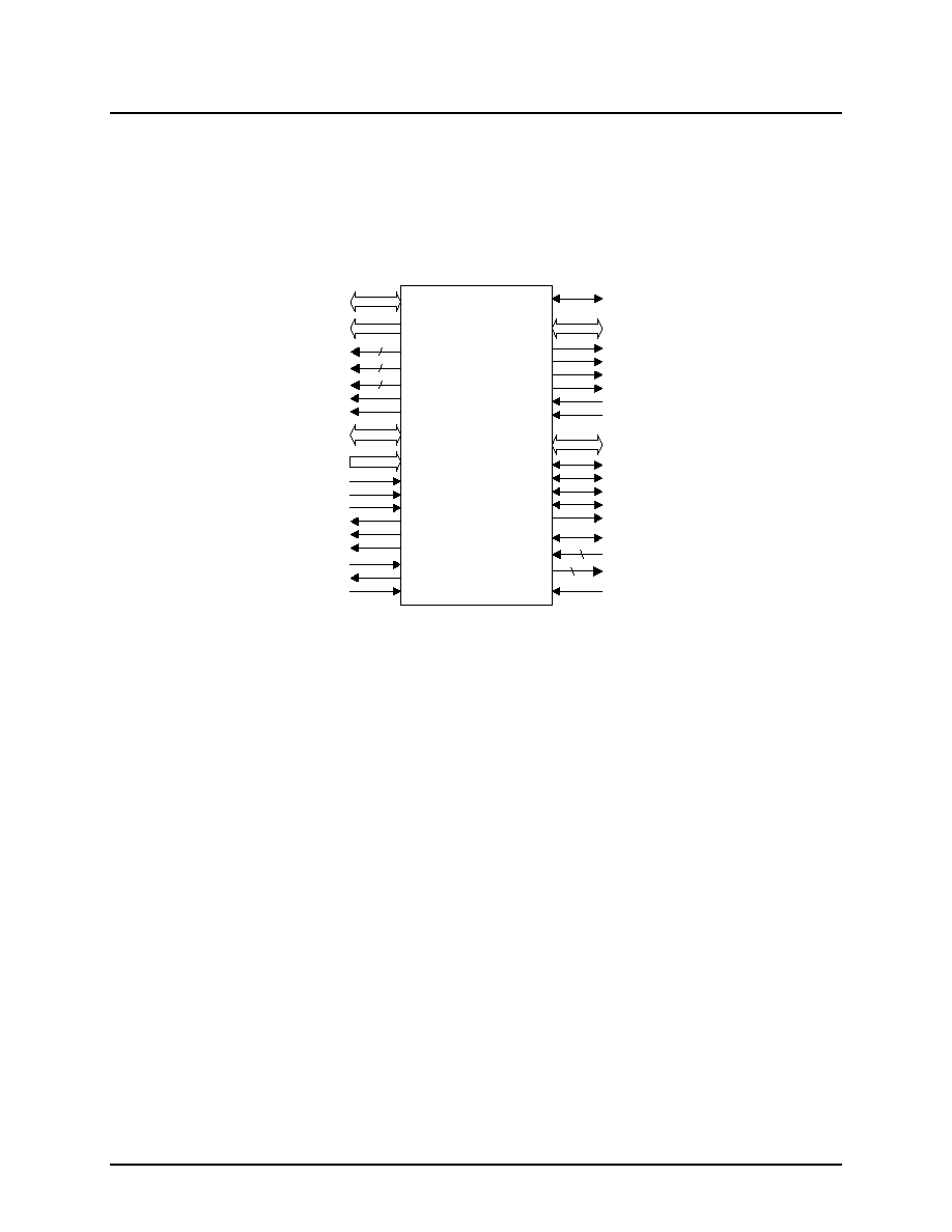
3.1 Logic Symbol
SC-201
T _ M O D E
C_D[15:0]
C _ C E #
C _ W E #
C _ C M #
C _ E C #
C _ M F #
C _ F F #
CAM Interface
Test Pin
S_D[31:0]
S _ M S G E N #
S _ E O F #
S _ I R D Y
S _ T A B T #
S _ O V L D #
4
4
S _ H P R E Q #
S_REQ[8:1]#
S_GNT[8:1]#
S _ C L K
XpressFlow
Bus Interface
Management Bus Interface
P_D[31:0]
P _ C S #
P _ A D S #
P _ R W C
P _ R D Y #
P _ B S 1 6 #
P _ I N T
P_A[11:1]
P _ R S T I N #
P _ R S T O U T
P _ C L K
L_D[31:0]
L_OE[3:0]#
L _ A D S C #
L _ C L K
L_A[18:2]
L _ W E [ 3 : 0 ] #
L _ B W E [ 3 : 0 ] #
4
4
Control Buffer
Memory Interface
4

P
R
E
L
I
M
I
N
A
R
Y
D
A
T
A
S
H
E
E
T
XpressFlowTM 2001 Series ≠
SC-201
Ethernet Switch Chipset
XpressFlow
Engine
©
1997
9
(57(;
1
(7:25.6
Page:
4
Rev. 4.1 ≠ December, 1997
3.2
Pin Assignment
Note:
#
Active low signal
Input
Input signal
In-ST
Input signal with Schmitt-Trigger
Output
Output signal (Tri-State driver)
Out-OD
Output signal with Open-Drain driver
I/O-TS
Input & Output signal with Tri-State driver
I/O-OD
Input & Output signal with Open-Drain driver
5VT
Input with 5V Tolerance
c
Output signal with programmable polarity.
Pin No(s).
Symbol
Type
Max
I
OL
/ I
OH
Name & Functions
Management Bus Interface
185,184,183,182,180,
179,177,176,175,174,
172,171,169,168,167,
166,164,163,160,159,
157,156,154,153,151,
150,149,148,146,145,
143,142
P_D[31:0]
TTL I/O-TS
(5VT)
16mA
Management Bus ≠ Data Bit [31:0]
211,210,208,207,205,
204,203,202,201,199,
198
P_A[11:1]
TTL In (5VT)
Management Bus ≠ Address Bit [11:1]
196
P_ADS#
TTL In (5VT)
Management Bus ≠ Address Strobe
191
P_RWC
TTL In (5VT)
Management Bus ≠ Read/Write Control
183
P_RDY#
TTL Out-OD
16mA
Management Bus ≠ Data Ready
184
P_BS16#
TTL Out-OD
16mA
Management Bus ≠ 16 bit Data Bus
185
P_CS#
TTL In (5VT)
Management Bus ≠ Chip Select
192
P_INT
?
TTL Output
4mA
Management Bus ≠ Interrupt Request
189
P_RSTIN#
TTL In-ST (5VT)
System RESET Input
190
P_RSTOUT
CMOS Output
16mA
CPU RESET Output
187
P_CLK
TTL In (5VT)
CPU Clock
XpressFlow Bus Interface
122,121,119,118,116
S_D[31:27] /
P_C[0:4]
CMOS I/O-TS
12mA
XpressFlow Bus ≠ Data Bit [31:27] or
Processor Interface Configuration Bit [0:4]
114,113,111,109,108,
106,105,104,103,101,
100,98,97,96,95,93,
92,90,89,88,87,85,84,
82,80,79,77
S_D[26:0]
CMOS I/O-TS
12mA
XpressFlow Bus ≠ Data Bit [27:0]
71
S_MSGEN#
CMOS I/O-TS
12mA
XpressFlow Bus ≠ Message Envelope
69
S_EOF#
CMOS I/O-TS
12mA
XpressFlow Bus ≠ End of Frame
72
S_IRDY
CMOS I/O-TS
12mA
XpressFlow Bus ≠ Initiator Ready
70
S_TABT#
CMOS I/O-OD
12mA
XpressFlow Bus ≠ Target Abort
123
S_HPREQ#
CMOS I/O-OD
12mA
XpressFlow Bus ≠ High Priority Request
140,138,135,133,131,
129,126,124
S_REQ[8:1]#
CMOS Input
XpressFlow Bus ≠ Bus Request [7:0]
141,139,137,134,132,
130,128,125
S_GNT[8:1]#
CMOS Output
4mA
XpressFlow Bus ≠ Bus Grant [7:0]
73
S_OVLD#
CMOS Output
12mA
XpressFlow Bus ≠ Bus Overload
75
S_CLK
CMOS Input
XpressFlow Bus ≠ Clock

P
R
E
L
I
M
I
N
A
R
Y
D
A
T
A
S
H
E
E
T
XpressFlowTM 2001 Series ≠
SC-201
Ethernet Switch Chipset
XpressFlow
Engine
©
1997
9
(57(;
1
(7:25.6
Page:
5
Rev. 4.1 ≠ December, 1997
Pin No(s).
Symbol
Type
Max
I
OL
/ I
OH
Name & Functions
Control Buffer Memory Interface
60,59,58,57,56,54,53,
51,50,49,48,47,46,45,
43,42,40,39,38,37,36,
34,33,30,29,27,26,25,
24,23,22,21
L_D[31:0]
TTL I/O-TS
8mA
Local Memory Bus ≠ Data Bit [31:0]
8,6,5,3,2,1,256,255,
254,253,251,250,248,
247,246,245,244
L_A[18:2]
TTL Output
8mA
Local Memory Bus ≠ Address Bit [17:2]
9
L_A[19] /
L_OE[3]#
TTL Output
8mA
Local Memory Bus ≠ Address Bit [19:18] or
Memory Read Chip Select [3]
63, 11, 19
L_OE[2:0]#
CMOS Output
2mA
Local Memory Bus- Read Chip Select [2:0]
242, 62, 10, 18
L_WE[3:0]#,
CMOS Output
2mA
Local Memory Bus ≠ Write Chip Select [3:0]
12,13,14,15
L_BWE[3:0]#
CMOS Output
8mA
Local Memory Bus ≠ Byte Write Enable
[3:0]
16
L_ADSC#
CMOS Output
8mA
Local Memory Bus ≠ Controller Addr.
Status
66
L_CLK
CMOS Output
8mA
Local Memory Bus ≠ Synchronous Clock
CAM Interface
214,215,217,218,219,
220,221,222,223,225,
226,228,229,220.221,
221
C_D[15:0]
TTL I/O-TS
(5VT)
4mA
CAM Interface ≠ Data Bus bit [15:0]
239
C_WE#
TTL Output
4mA
CAM Interface ≠ Write Enable
241
C_CE#
TTL Output
4mA
CAM Interface ≠ Chip Enable
233
C_EC#
TTL Output
4mA
CAM Interface ≠ Enable Comparison
234
C_CM#
TTL Output
4mA
CAM Interface ≠ Data/Command Select
236
C_FF#
TTL In (5VT)
CAM Interface ≠ Full Flag
237
C_MF#
TTL In (5VT)
CAM Interface ≠ Match Flag
Test & Reserved Pins
65
T_MODE
CMOS I/O-TS
with Pull-Up
2mA
Test Pin ≠ Set Test Mode upon Reset, and
provides test status output during test
mode
62,63,64,67,242
n/c
n/a
Reserved Pins (5 pins)
Pin No(s).
Symbol
Type
Name & Functions
Power Pins
32,78,115,161,206,243
VDD (Core)
Power
+3.3 Volt DC Supply for Core Logic (6 pins)
7,20,31,44,55,68,76,86,94,102,110,
120,144,152,162,170,178,186,197,
216,227,238,252
VDD
Power
+3.3 Volt DC Supply for I/O Pads (23 pins)
35,81,112,158,209,240
VSS (Core)
Power
Ground for Core Logic (6 pins)
4,17,28,41,52,61,66,74,83,91,99,197,
117,127,136,147,155,165,173,181,
188,200,213,224,235,249
VSS
Power
Ground for I/O Pads (26 pins)