 | –≠–ª–µ–∫—Ç—Ä–æ–Ω–Ω—ã–π –∫–æ–º–ø–æ–Ω–µ–Ω—Ç: MSC220AL | –°–∫–∞—á–∞—Ç—å:  PDF PDF  ZIP ZIP |

P R E L I M I N A R Y I N F O R M A T I O N
© 1998 Vertex Networks, Inc. 1 Rev. 4.5 ≠ February
1999
Distinctive Characteristics
t
Highly integrated central switch controller
t
State of the art 0.35 micron 3.3 Volt CMOS
process
t
256-PIN PQFP package
t
Operating frequency
-40
40 MHz maximum
-50
50 MHz maximum
-66
66 MHz maximum
t
16-bit external CAM interface
Supports Ωk to 16k MAC addresses
t
32-bit Control Buffer Memory interface
Supports 128k to 1M bytes
Utilize high performance 32-bit Syn-
chronous Burst SRAM
t
Hardware assisted Buffer and Queue Man-
agement to minimize CPU overhead
t
32-bit Management Bus I/O interface
Allows host to access CAM and Control
Buffer Memory
Supports Big and Little Endian CPUs
Direct interface with various different
standard microprocessors including
386, 486 families and Motorola MPC se-
ries embedded processors
t
32-bit XpressFlow Bus Interface
Switching bandwidth
-
1.28 Gbps @ 40 MHz system clock
-
1.60 Gbps @ 50 MHz system clock
-
2.10 Gbps @ 66.67 MHz system clock
Supports up to 8 Multi-port Network Ac-
cess Controllers
XpressFlow Bus access arbitration
XpressFlow Bus data transfer load
regulation
t
Full IP Switching
Addresses resolved by SC220
t
MAC Address Mapping Table
Supports either CAM based or SRAM
based Switching data base
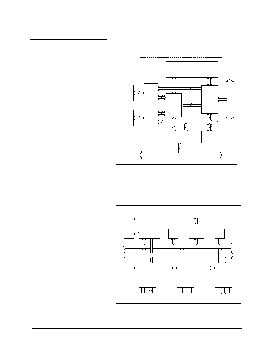
SC220 ≠ XpressFlow Engine
XpressFlow 2020 Ethernet Routing Switch Chipset
CONTROL
BUFFER
MEMORY
XpressFlow BUS
XpressFlow BUS
32
32
32
SC220
XpressFlow
ENGINE
ADDRESS
MAPPING
TABLE
16
C A M
(Optional)
SC220 - XpressFlow Engine
General Description
The XpressFlow Engine contains the switching data base in-
terface and buffer management logic in order to do the switching
decision making for unicast, multicast, and broadcast frames.
Hardware assisted queue manager is incorporated to facilitate
buffer management. It also provides a generic Management Bus
interface to allow external processor to do initialization, learning,
VLAN, and RMON support, etc. In addition, a XpressFlow Bus
interface block is responsible for communicating with the Network
Access Controllers through the XpressFlow message passing
protocol.
Related Components:
t
EA218E
≠ 8-port 10Mbps Ethernet Access Controller
t
EA218
≠ 6-port 10 + 2-port 10/100 Ethernet Access Controller
t
EA234
≠ 4-port 10/100 Fast Ethernet
P
R
E
L
I
M
I
N
A
R
Y
I
N
F
O
R
M
A
T
I
O
N
XpressFlow-2020 Series ≠
SC220
Ethernet Switch Chipset
XpressFlow Engine
© 1998 Vertex Networks, Inc. 2 Rev. 4.5 ≠ February
1999
Characteristics Continue
t
Built-in address to port resolution
Embedded 32-bit HISCTM (High density
Instruction Set Core) Processor
Optimized architecture for switch appli-
cations
Loadable firmware for easy upgrade
t
Supports unicast, multicast, and broadcast
frames
t
Address Filtering
Destination & Source MAC address
matching & filtering
t
VLAN classification & verification
Up to 62 groups
Level 1 and 2 mapping
VLAN ID tagging & stripping
Auto padding if necessary after stripping
t
Supports Store-&-Forward Frame Forward-
ing Mode
t
Collects statistics for RMON
CONTROL
BUFFER
MEMORY
MANAGEMENT-BUS
XpressFlow BUS
XpressFlow Bus
Interafce
32
32
32
Automatic
Buffer
Manager
Mngmt
Bus
Interface
32
32
Control
Buffer
Memory
Interface
HISC
I/O
Registers
32
CAM
Interface
ADDRESS
MAPPING
TABLE
32
32
16
HISC Core
32
16
32
32
32
CAM
SRAM
16
SC220
XpressFlow
Engine
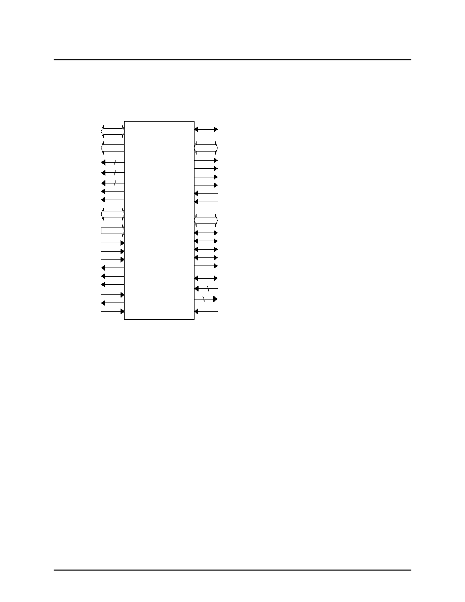
Block Diagram ≠
SC220 XpressFlow Engine
Typical Application
:
A 16-port Ethernet Switch with 4-Fast Ethernet
Address
Mapping
Table
Flash
ROM
SC220
X
pressFlow
Engine
EA208E
8-Port
Ethernet
Access
Controller
Management Bus
Buffer
RAM
Switch
Manager
CPU
DRAM
RS232 Local
Control Console
Buffer
RAM
8 Ethernet ports
Buffer
RAM
8 Ethernet ports
XpressFlow Bus
EA208E
8-Port
Ethernet
Access
Controller
Buffer
RAM
Four 100M
Fast Ethernet ports
EA234
4-Port
Ethernet
Access
Controller
System Block Diagram --
16-Port Ethernet Switch with 4 Fast Ethernet Up-Links
P
R
E
L
I
M
I
N
A
R
Y
I
N
F
O
R
M
A
T
I
O
N
XpressFlow-2020 Series ≠
SC220
Ethernet Switch Chipset
XpressFlow Engine
© 1998 Vertex Networks, Inc. 3 Rev. 4.5 ≠ February
1999
1.
PIN ASSIGNMENT
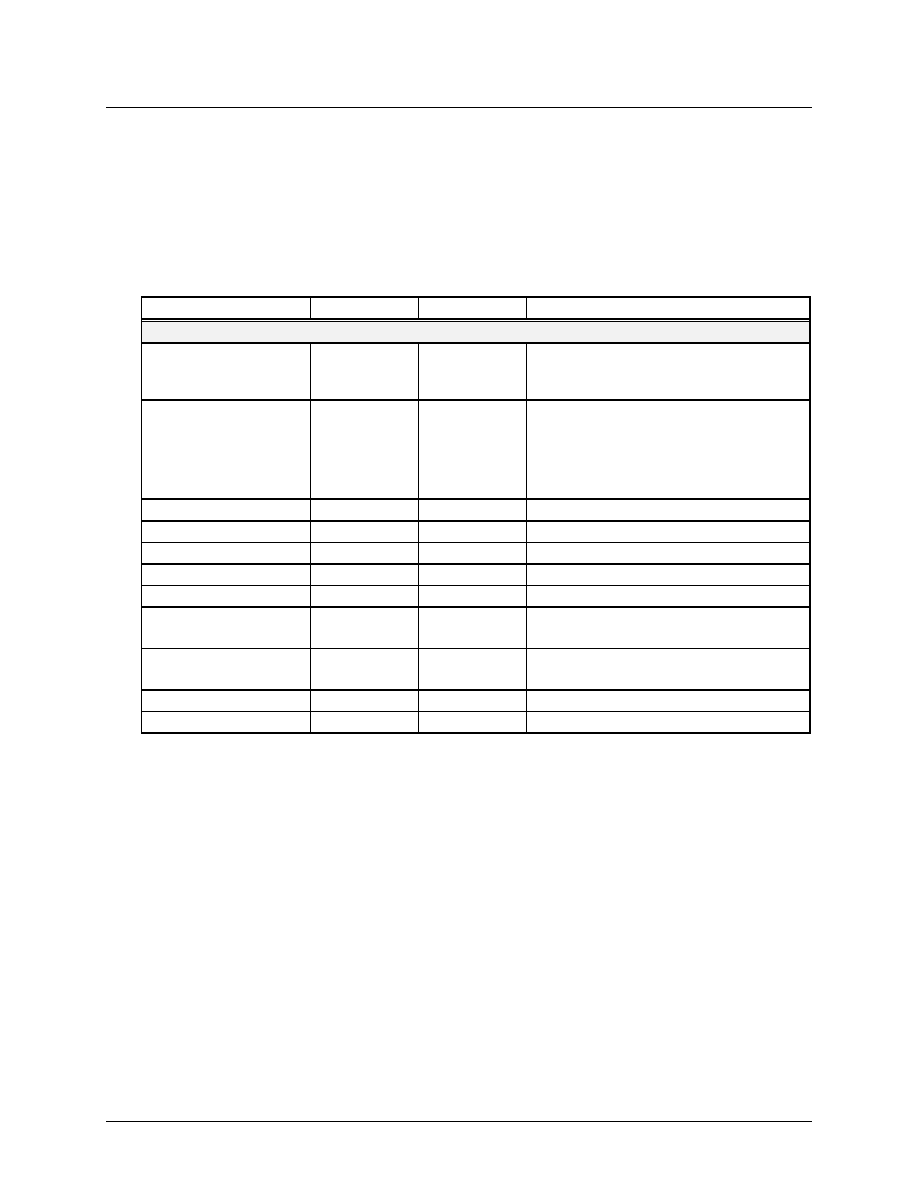
1.1 Logic Symbol
SC220
T_MODE
C_D[15:0]
C_CE#
C_WE#
C_CM#
C_EC#
C_MF#
C_FF#
CAM Interface
Test Pin
S_D[31:0]
S_MSGEN#
S_EOF#
S_IRDY
S_TABT#
S_OVLD#
8
8
S_HPREQ#
S_REQ[8:1]#
S_GNT[8:1]#
S_CLK
XpressFlow
Bus Interface
Management Bus Interface
P_D[31:0]
P_CS#
P_ADS#
P_RWC
P_RDY#
P_BS16#
P_INT
P_A[11:1]
P_RSTIN#
P_RSTOUT
P_CLK
L_D[31:0]
L_OE[3:0]#
L_ADSC#
L_CLK
L_A[18:2]
L_WE[3:0]#
L_BWE[3:0]#
4
4
Control Buffer
Memory Interface
4
Note:
The SC220 is pin compatible to the SC201 with only one exception:
The RSTOUT pin of SC201 is defined as a synchronous RESET output pin which follows the RSTIN input and re-synchronous with
P_CLK for meeting the 80386 timing requirement.
The RSTOUT pin for SC220 has a totally different function. It is no longer related with the RSTIN input. The RSTOUT is a watch-
dog output from SC220 to keep track of the active state of the host processor. Host processor needs to access the Keep
Alive register periodically to prevent the setting of the RSTOUT output. The RSTOUT output can be use as Reset input to
the host processor.
P
R
E
L
I
M
I
N
A
R
Y
I
N
F
O
R
M
A
T
I
O
N
XpressFlow-2020 Series ≠
SC220
Ethernet Switch Chipset
XpressFlow Engine
© 1998 Vertex Networks, Inc. 4 Rev. 4.5 ≠ February
1999
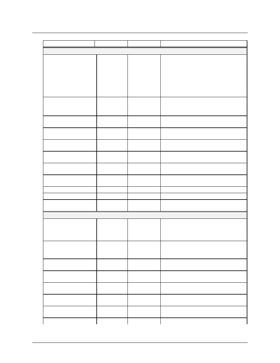
1.2 Pin Assignment
(Preliminary)
Note:
#
Active low signal
Input
Input signal
I-ST
Input signal with Schmitt-Trigger
Output
Output signal (Tri-State driver)
Out-OD
Output signal with Open-Drain driver
I/O-TS
Input & Output signal with Tri-State driver
I/O-OD
Input & Output signal with Open-Drain driver
5VT
Input with 5V Tolerance
Pin No(s).
Sy mbol
Type
Name & Functions
XpressFlow Bus Interface
122,121,119,118, 116
S_D[31:27] /
P_C[0:4]
CMOS I/O-TS XpressFlow Bus ≠ Data Bit [31:28] or
Processor Interface Configuration Bit
[0:4]
114,113,111,109,108,
106,105,104,103,101,
100,98,97,96,95,93,92,
90,89,88,87,85,84,82,
80,79,77
S_D[26:0]
CMOS I/O-TS XpressFlow Bus ≠ Data Bit [27:0]
71
S_MSGEN#
CMOS I/O-TS XpressFlow Bus ≠ Message Envelope
69
S_EOF#
CMOS I/O-TS XpressFlow Bus ≠ End of Frame
72
S_IRDY
CMOS I/O-TS XpressFlow Bus ≠ Initiator Ready
70
S_TABT#
CMOS I/O-OD XpressFlow Bus ≠ Target Abort
123
S_HPREQ#
CMOS I/O-OD XpressFlow Bus ≠ High Priority Request
140,138,135,133,131,
129,126,124
S_REQ[8:1]#
CMOS Input ** XpressFlow Bus ≠ Bus Request [8:1]
141,139,137,134,132,
130,128,125
S_GNT[8:1]#
CMOS Output XpressFlow Bus ≠ Bus Grant [8:1]
73
S_OVLD#
CMOS Output XpressFlow Bus ≠ Bus Overload
75
S_CLK
CMOS Input XpressFlow Bus ≠ Clock
P
R
E
L
I
M
I
N
A
R
Y
I
N
F
O
R
M
A
T
I
O
N
XpressFlow-2020 Series ≠
SC220
Ethernet Switch Chipset
XpressFlow Engine
© 1998 Vertex Networks, Inc. 5 Rev. 4.5 ≠ February
1999
Pin No(s).
Sy mbol
Type
Name & Functions
XpressFlow Bus Interface
185,184,183,182,180,
179,177,176,175,174,
172,171,169,168,167,
166,164,163,160,159,
157,156,154,153,151,
150,149,148,146,145,
143,142
P_D[31:0]
TTL I/O-TS
(5VT)
Management Bus ≠ Data Bit [31:0]
211,210,208,207,205,
204,203,202,201,199,
198
P_A[11:1]
TTL Input
(5VT)
Management Bus ≠ Address Bit [11:1]
196
P_ADS#
TTL Input
(5VT)
Management Bus ≠ Address Strobe
191
P_RWC
TTL Input
(5VT)
Management Bus ≠ Read/Write Control
183
P_RDY#
CMOS Out-
OD
Management Bus ≠ Data Ready
184
P_BS16#
CMOS Out-
OD
Management Bus ≠ 16 bit Data Bus
185
P_CS#
TTL Input
(5VT)
Management Bus ≠ Chip Select
189
P_RSTIN#
TTL In-ST
(5VT)
System RESET Input
190
P_RSTOUT
CMOS Output CPU RESET Output
192
P_INT
CMOS Output Management Bus ≠ Interrupt Request
187
P_CLK
TTL Input
(5VT)
CPU Clock
Control Buffer Memory Interface
60,59,58,57,56,54,53,51,
50,49,48,47,46,45,43,42,
40,39,38,37,36,34,33,30,
29,27,26,25,24,23,22,21,
L_D[31:0]
TTL I/O-TS
Local Memory Bus ≠ Data Bit [31:0]
8,6,5,3,2,1,256,255,254,
253,251,250,248,247,
246,245,244
L_A[18:2]
CMOS Output Local Memory Bus ≠ Address Bit [17:2]
9
L_A[19] /
L_OE[3]#
CMOS Output Local Memory Bus ≠ Address Bit [19:18]
or Memory Read Chip Select [3]
63, 11, 19
L_OE[2:0]#
CMOS Output Local Memory Bus- Read Chip Select
[2:0]
242, 62, 10, 18
L_WE[3:0]#,
CMOS Output Local Memory Bus ≠ Write Chip Select
[3:0]
12,13,14,15
L_BWE[3:0]# CMOS Output Local Memory Bus ≠ Byte Write Enable
[3:0]
16
L_ADSC#
CMOS Output Local Memory Bus ≠ Controller Address
Status
66
L_CLK
CMOS Output Local Memory Bus ≠ Synchronous Clock