 | –≠–ª–µ–∫—Ç—Ä–æ–Ω–Ω—ã–π –∫–æ–º–ø–æ–Ω–µ–Ω—Ç: MT90401AB | –°–∫–∞—á–∞—Ç—å:  PDF PDF  ZIP ZIP |
Document Outline
- Features
- Applications
- Figure 1 - Functional Block Diagram
- Description
- Figure 2 - Pin Connections 80 Pin LQFP for MT90401
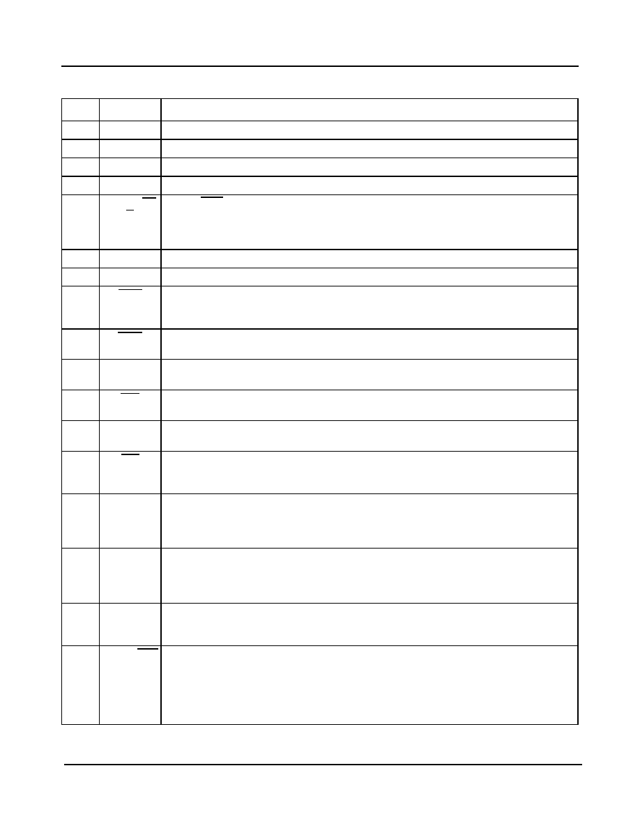
- Pin Description �
- 1.0 Functional Description
- 1.1 Reference Select MUX Circuit
- 1.2 Frequency Select MUX Circuit
- Table 1 - Frequency Selection
- 1.3 Time Interval Error (TIE) Corrector Circuit
- Figure 3 - TIE Corrector Circuit
- 1.4 Digital Phase Lock Loop (DPLL)
- Figure 4 - DPLL Block Diagram
- 1.5 Output Interface Circuit
- Figure 5 - Output Interface Circuit Block Diagram
- 1.6 Input Impairment Monitor
- 1.7 State Machine Control
- Figure 6 - Control State Machine Block Diagram
- 1.8 Master Clock
- 2.0 Control and Mode of Operation
- Table 2 - Input Reference Selection
- Table 3 - Operating Modes and States
- 2.1 Normal Mode
- 2.2 Holdover Mode
- 2.3 Freerun Mode
- 2.4 Fast Lock Mode
- 2.5 Transitions from Freerun Mode or Holdover Mode to Normal Mode
- 3.0 MT90401 Measures of Performance
- 3.1 Jitter Generation
- 3.2 Jitter Tolerance
- Figure 7 - Jitter Tolerance GR-1244 1.544�MHz Reference
- Figure 8 - Jitter Tolerance ITU-T G.813 Option�1
- Figure 9 - Jitter Tolerance SONET Category II (OC1) 19.44 MHz Input Reference
- 3.3 Jitter Transfer
- Figure 10 - Jitter and Wander Transfer with SONET filter
- Figure 11 - Jitter and Wander Transfer with SDH Filter
- Table 4 - Control State Table
- Figure 12 - Control State Diagram
- 3.4 Frequency Accuracy
- 3.5 Holdover Accuracy
- 3.6 Capture Range
- 3.7 Lock Range
- 3.8 Phase Slope
- 3.9 Frequency Slope
- 3.10 Time Interval Error (TIE)
- 3.11 Maximum Time Interval Error (MTIE)
- 3.12 Phase Continuity
- 3.13 Phase Lock Time
- 4.0 MT90401 and Network Specifications
- 5.0 Applications
- 5.1 Master Clock
- 5.2 TIE Correction (using PCCi)
- 5.3 C155 clock generation and LVDS output drivers
- Figure 13 - LVDS Voltage Offset Vos Generation Circuit
- 5.4 Microport
- 5.5 Output Phase Adjustment
- Table 5 - Register Map�
- Table 6 - Control Register 1 (Address 00H - Read/Write)�
- Table 7 - Status Register 1 (Address 01H - Read Only)
- Table 8 - Control Register 2 (Address 04H - Read/Write)
- Table 9 - Set Delay Word 2 (Address 06H - Read/Write)
- Table 10 - Set Delay Word 1 (Address 07H - Read/Write)
- Table 11 - Identification Word (Address 0FH - Read Only)
- Absolute Maximum Ratings*
- Recommended Operating Conditions*
- DC Electrical Characteristics*
- AC Electrical Characteristics - Timing Parameter Measurement Voltage Levels*
- Figure 14 - Timing Parameter Measurement Voltage Levels
- AC Electrical Characteristics - Microprocessor Timing*
- Figure 15 - Microport Timing
- Figure 16 - Input to Output Timing for T1/E1 signals (Normal Mode)
- Figure 17 - Input to Output Timing for 19.44�MHz Signal (Normal Mode)
- AC Electrical Characteristics - Output Timing*�
- Figure 18 - Output Timing 1
- Figure 19 - Output Timing 2
- Figure 20 - Input Controls Setup and Hold Timing
- Figure 21 - Output Timing 3
- AC Electrical Characteristics - C20i Master Clock Input*
- Performance Characteristics: Mode Switching*
- Performance Characteristics: Output Jitter Generation - Filtered�
- Performance Characteristics: Output Jitter Generation - Filtered (VDD = 3.3V +/- 10%, TA = -5∞C t...
- Performance Characteristics: Output Jitter Generation - Unfiltered*

1
Zarlink Semiconductor Inc.
Zarlink, ZL and the Zarlink Semiconductor logo are trademarks of Zarlink Semiconductor Inc.
Copyright 2003-2005, Zarlink Semiconductor Inc. All Rights Reserved.
Features
∑ Meets requirements of GR-253-CORE for SONET
Stratum 3 and SONET minimum clock
∑ Meets requirements of GR-1244-CORE Stratum 3
∑ Meets requirements of G.813 Option 1 and Option
2 for SDH Equipment Clocks (SEC) with external
jitter attenuator
∑ Provides OC-3/STM-1, DS3, E3, 19.44 MHz,
DS2, E1, T1, 8 kHz and ST-BUS clock outputs
∑ Accepts reference inputs from two independent
sources
∑ Selectable 1.544 MHz, 2.048 MHz, 19.44 MHz or
8kHz input reference frequencies
∑ Holdover accuracy of 0.02 ppm
∑ Adjustable output clock phase supporting master-
slave arrangements
∑ Hardware or microprocessor control (8 bit
microprocessor interface)
∑ 3.3 V supply
∑ JTAG boundary scan
Applications
∑ SONET/SDH Add/Drop multiplexers
∑ SONET/SDH uplinks
∑ Integrated access devices
∑ ATM edge switches
Description
The MT90401 is a digital phase locked loop (DPLL)
that is designed to synchronize SDH (Synchronous
Digital Hierarchy) and SONET (Synchronous Optical
Network) networking equipment. The MT90401 is used
to ensure that the timing of outgoing signals remains
within the limits specified by Telcordia, ANSI and the
ITU during normal operation and in the presence of
disturbances on the incoming synchronization signals.
January 2005
Ordering Information
MT90401AB
80 Pin LQFP
Trays
MT90401AB1 80 Pin LQFP*
Trays
*Pb Free Matte Tin
-40
∞C to +85∞C
MT90401
SONET/SDH System Synchronizer
Data Sheet
Figure 1 - Functional Block Diagram
Virtual
Reference
Selected
Refer-
ence
IEEE
1149.1a
Reference
Select
Feedback
TIE
Corrector
Enable
Control State Machine
DPLL
State
Select
State
Select
Frequency
Select
MUX
Input
Impairment
Monitor
Output
Interface
Circuit
Reference
Select
MUX
TIE
Corrector
Circuit
MS1 MS2
FS1
FS2
TCK
SEC
RST
RSEL
VDD
VSS
TCLR
C1.5o
C19o
C2o
C4o
C8o
C16o
C44/C34
F0o
F8o
TDO
TDI
TMS
TRST
C6o
HOLDOVER
FLOCK
LOCK
Reference
Monitor
Prioor
Secoor
D0/D7 A0/A6 CS,DS,R/W
C155P/N
C20i
F16o
Master Clock
PCCi
PRI

MT90401
Data Sheet
2
Zarlink Semiconductor Inc.
The MT90401 can operate in free-run, locked or holdover mode. The loop filter corner frequency can be selected to
suit SONET applications or to suit SDH applications. The MT90401 uses an external 20 MHz oscillator as its
master clock and it does not require external loop filter components.
In Hardware Mode, the MT90401 can be controlled and monitored via external pins. In Microport Mode, a
microprocessor can be used for more comprehensive control and monitoring.
Figure 2 - Pin Connections 80 Pin LQFP for MT90401
MT90401AB
40
42
44
46
48
50
52
54
56
58
60
22
24
26
28
30
34
36
38
32
62
80
78
76
74
72
68
66
64
70
20
18
16
14
12
10
8
6
4
2
Tdi
Tclk
Tms
Tdo
VREF
VSS4
PRI
SEC
E3/DS3
E3DS3/OC3
C155P
C155N
VDD
VDD2
VSS3
IC
VSS2
FS1
Trst
FS2
MS1
A2
A1
C4
o
C8
o
C1
6o
F1
6o
V
SS1
VDD
1
SONET/SDH
A5
F0
o
C2
o
IC
A3
A4
MS2
V
SS9
A6
F8o
SECOOR
OE
CS
RST
HW
D1
D2
D3
VSS8
IC
D6
R/W
IC
VDD5
D4
D5
D7
IC
A0
C1
.5
o
C
19o
R
SEL
TC
LR
VD
D3
NC
C
20i
C
34/
C
4
4
VSS
7
VD
D4
H
O
L
D
OVER
PC
Ci
LO
CK
FL
OCK
DS
IC
PRI
OOR
VSS
5
IC
C6
o
D0
MT90401
Data Sheet
3
Zarlink Semiconductor Inc.
Pin Description
Pin #
Name
Description
1
IC
Internal Connection. Leave unconnected.
2-5
A1 - A4
Address 1 to 4 (5 V tolerant Inputs). Address inputs for the parallel processor interface.
6
V
SS9
Digital ground. 0 Volts
7, 8
A5, A6
Address 5, to 6 (5 V tolerant Input). Address inputs for the parallel processor interface.
9
SONET/SD
H
SONET/SDH (Input). In hardware mode set this pin high to have a loop filter corner
frequency of 70 millihertz and limit the phase slope to 885 ns per second. Set this pin low to
have a corner frequency of approximately 1.1 hertz and limit the phase slope to 53 ns per
1.326 ms. This pin performs no function if the device is not in hardware mode.
10
V
DD1
Positive Power Supply. Digital supply.
11
V
SS1
Digital ground. 0 Volts
12
F16o
Frame Pulse ST-BUS 8.192 Mb/s (CMOS Output). This is an 8kHz 61ns active low
framing pulse, which marks the beginning of an ST-BUS frame. This is typically used for ST-
BUS operation at 8.192 Mb/s.
13
C16o
Clock 16.384 MHz (CMOS Output). This output is used for ST-BUS operation with a
16.384 MHz clock.
14
C8o
Clock 8.192 MHz (CMOS Output). This output is used for ST-BUS operation at
8.192 Mb/s.
15
C4o
Clock 4.096 MHz (CMOS Output). This output is used for ST-BUS operation at 2.048 Mb/s
and 4.096 Mb/s.
16
C2o
Clock 2.048 MHz (CMOS Output). This output is used for ST-BUS operation at
2.048 Mb/s.
17
F0o
Frame Pulse ST-BUS 2.048 Mb/s (CMOS Output). This is an 8 kHz 244 ns active low
framing pulse, which marks the beginning of an ST-BUS frame. This is typically used for ST-
BUS operation at 2.048 Mb/s and 4.096 Mb/s.
18
MS1
Mode/Control Select 1 (Input). This input, together with MS2, determines the state
(Normal, Holdover, or Freerun) of operation. See Table 3 on page 15. The logic level at this
input is gated in by the rising edge of F8o. This pin performs no function if the device is not
in hardware mode.
19
MS2
Mode/Control Select 2 (Input). This input, together with MS1, determines the state
(Normal, Holdover or Freerun) of operation. See Table 3 on page 15. The logic level at this
input is gated in by the rising edge of F8o. This pin performs no function if the device is not
in hardware mode.
20
F8o
Frame Pulse Generic (CMOS Output). This is an 8 kHz 122 ns active high framing pulse,
which marks the beginning of a TDM frame. This is typically used for TDM streams
operating at 8.192 Mb/s.
21
E3DS3/OC3 E3DS3 or OC-3 Selection (Input). In Hardware Mode a low on this pin enables the
differential 155.52 MHz output clock on the C155N/C155P pins; this will also cause the
C34/C44 pin to output its nominal clock frequency divided by 4. In Hardware Mode, a high
on this pin disables the differential 155.52 MHz output clock on the C155N/C155P pins; this
will also cause the C34/C44 pin to output its nominal clock frequency. This pin performs no
function if the device is not in Hardware Mode.

MT90401
Data Sheet
4
Zarlink Semiconductor Inc.
22
E3/DS3
E3 or DS3 Selection (Input). In Hardware Mode a low on this pin selects a clock rate of
44.736 MHz for the C34/C44 pin, while a high selects a clock rate of 34.368 MHz. This pin
performs no function if the device is not in hardware mode.
23
SEC
Secondary Reference (Input). This is one of two (PRI & SEC) input reference sources
(falling edge) used for synchronization. One of four possible frequencies ( 8kHz,
1.544 MHz, 2.048 MHz or 19.44 MHz) may be used. In hardware mode the selection of the
input reference is based upon the MS1, MS2 and RSEL control inputs.
24
PRI
Primary Reference (Input). This is one of two (PRI & SEC) input reference sources
(falling edge) used for synchronization. One of four possible frequencies (8 kHz,
1.544 MHz, 2.048 MHz or 19.44 MHz) may be used. In hardware mode the selection of the
input reference is based upon the MS1, MS2 and RSEL control inputs.
25
V
SS2
Digital ground. 0 Volts
26
IC
Internal Connection. Leave unconnected
27
V
SS3
Analog ground. 0 Volts
28
V
DD2
Positive Analog Power Supply. Analog supply.
29
V
DD
Positive Power Supply. Digital supply.
30
31
C155N,
C155P
LVDS 155.52 MHz (Output)). Differential outputs generating a 155.52 MHz clock
32
V
SS4
Digital ground. 0 Volts
33
VREF
LVDS Reference Voltage (Input).
34
Tdo
IEEE 1149.1a Test Data Output (Output). If not used, this pin should be left unconnected.
35
Tms
IEEE 1149.1a Test Mode Selection (Input). If not used, this pin should be pulled high.
36
Tclk
IEEE 1149.1a Test Clock Signal (Input). If not used, this pin should be pulled high.
37
Trst
IEEE 1149.1a Reset Signal (Input). If not used, this pin should be held low.
38
Tdi
IEEE 1149.1a Test Data Input (Input). If not used, this pin should be pulled high.
39
FS2
Frequency Select 2 (Input). This input, in conjunction with FS1, selects which of four
possible frequencies (8 kHz, 1.544 MHz, 2.048 MHz or 19.44 MHz) may be input to the PRI
and SEC inputs. For more details see FS2 bit description in Table 6 - Control Register 1
(Address 00H - Read/Write).
40
FS1
Frequency Select 1 (Input). This input, in conjunction with FS2, selects which of four
possible frequencies (8 kHz, 1.544 MHz, 2.048 MHz or 19.44 MHz) may be input to the PRI
and SEC inputs. For more details see FS1 bit description in Table 6 - Control Register 1
(Address 00H - Read/Write).
41
PRIOOR
Primary Reference Out Of Range (CMOS Output). A logic high at this pin indicates that
the primary reference is off the PLL center frequency by more than 12 ppm. The
measurement is done on a 1 second basis using a signal derived from the 20 MHz clock
input on C20i. When the accuracy of the 20 MHz clock is
±
4.6 ppm, the effective out of
range limits of the PRIOOR signal will be
+
16.6 ppm to -7.4 ppm or +7.4 ppm to -16.6 ppm.
42
C1.5o
Clock 1.544 MHz (CMOS Output). This output is used in T1 applications.
43
C6
Clock 6.312 MHz (CMOS Output). This output is used for DS2 or J2 applications.
44
IC
Internal Connection. Tie low for normal operation.
Pin Description (continued)
Pin #
Name
Description

MT90401
Data Sheet
5
Zarlink Semiconductor Inc.
45
V
SS5
Digital ground. 0 Volts
46
C19o
Clock 19.44 MHz (CMOS Output). This output is used in OC-N and STM-N applications.
47
RSEL
Reference Source Select (Input). A logic low selects the PRI (primary) reference source
as the input reference signal and a logic high selects the SEC (secondary) input. The logic
level at this input is gated in by the rising edge of F8o. For more details see RSEL bit
description in Table 6 - Control Register 1 (Address 00H - Read/Write).
48
TCLR
TIE Circuit Clear (Input). A logic low at this input clears the Time Interval Error (TIE)
correction circuit resulting in a realignment of output phase with input phase. The TCLR pin
should be held low for a minimum of 300 ns. When this pin is held low, the time interval error
correction circuit is disabled.
49
V
DD3
Positive Power Supply. Digital supply.
50
NC
No Connection.
51
C20i
20 MHz Clock Input (5 V tolerant Input). This pin is the input for the master 20 MHz clock.
52
V
SS7
Digital ground. 0Volts
53
C34/C44
Controlled Clock 34.368 MHz / Clock 44.736 MHz (CMOS Output). This output clock is
programmable to be either 34.368 MHz (for E3 applications) or 44.736 MHz (for DS3
applications). The output clock is controlled via control pins in Hardware Mode or control
bits when the device is in Microport Mode.
If the E3DS3/OC3 control pin or control bit is high, the C34/C44 pin will output its nominal
frequency. If the E3DS3/OC3 control pin or bit is low, the C34/C44 pin will output its nominal
frequency divided by 4. (C8.5o/C11o)
54
V
DD4
Positive Power Supply. Digital supply.
55
HOLDOVER Holdover (CMOS Output). This output goes high when the device is in holdover mode.
56
PCCi
Phase Continuity Control Input (3 V Input). The signal at this pin affects the state
changes between Primary Holdover Mode and Primary Normal Mode and Primary Holdover
Mode and Secondary Normal Mode. The logic level at this input is gated by the rising edge
of F8o. See Figure 12, "Control State Diagram" on page 21 for details.
57
LOCK
Lock Indicator (CMOS Output). This output goes high when the PLL is in frequency lock
to the input reference.
58
FLOCK
Fast Lock Mode (Input). In hardware mode, hold this pin high to lock faster than normal to
the input reference. This pin performs no function if the device is not in hardware mode. In
Fast Lock Mode, the wander generation of the PLL is, of necessity, compromised.
59
DS
Data Strobe (5 V tolerant Input). This input is the active low data strobe of the Motorola
processor interface.
60
IC
Internal Connection. Tie low for normal operation.
61
SECOOR Secondary Reference Out Of Capture Range (CMOS Output). A logic high at this pin
indicates that the secondary reference is off the PLL center frequency by more than 12
ppm. The measurement is done on a 1 second basis using a signal derived from the
20 MHz clock input on the C20i pin. When the accuracy of the 20 MHz clock is
±
4.6 ppm
the effective out of range limits of the SECOOR signal will be
+
16.6 ppm to -7.4 ppm or
+7.4 ppm to -16.6 ppm.
Pin Description (continued)
Pin #
Name
Description