SP8902 (MP)
5GHZ 4
4
4
4
42 Fixed Modulus Divider
Preliminary Information
DS4375 Issue 1.4 September 1999
Ordering Information
SP8902/KG/MP1S (tubes)
SP8902/KG/MP1T (tape and reel)
The SP8902 is one of a range of very high speed low
power prescalers for professional applications. The dividing
elements are static D type flip flops and therefore allow
operation down to DC if the drive signal is a pulse waveform
with fast risetime. The output stage has a differential current
output and provides a direct drive into a 50 ohm load.
Features
G
Very High Operating Speed
G
Operation down to DC with Square Wave Input
G
Silicon Technology for Low Phase Noise
(Typically better than 2140dBc/Hz at 1KHz)
G
5V Single Supply Operation
G
Low Power Dissipation: 335mW (Typ.)
G
Surface Mount Plastic Package
Absolute Maximum Ratings
Supply voltage, V
CC
Storage temperature
Maximum junction temperature
Prescaler input voltage
Operating temperature
6�5V
265
�C to 1150�C
1150
�C
2�5Vp-p
KG240
�C to 185�C T
CASE
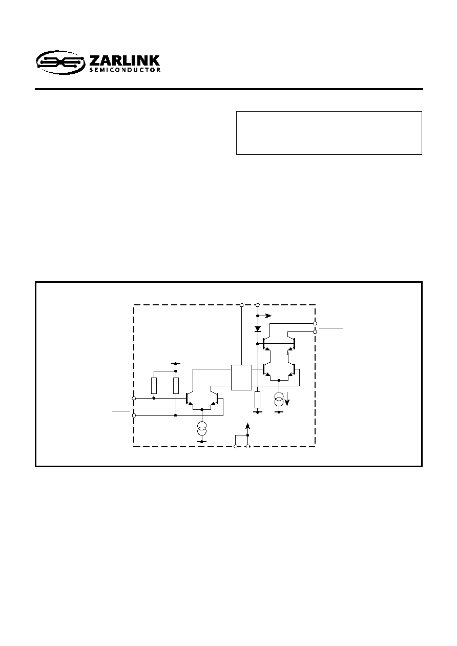
Figure 1 block diagram
4
2
400
400
V
CC
V
REF
OUTPUT
V
CC
10mA
OUTPUT
OUTPUT
1
8
7
6
2
3
INPUT
INPUT
4
4
GND

2
SP8902
1
2
3
4
8
7
6
5
OUTPUT V
CC
OUTPUT
OUTPUT
GND
V
CC
INPUT
INPUT
GND
MP8
Figure 2 Pin connections - top view
Electrical Characteristics
These characteristics are guaranteed by either production test or design over the following range of operating conditions
unless otherwise stated: T
AMB
= 240
�C to 185�C, V
CC
= 4�75V to 5�25V
-
1�0
-
-
440
700
-
215�0
Characteristic
RMS sinewave
f
IN
= 1GHz and 4.2GHz
f
IN
= 5GHz
f
IN
= 1GHz and 3GHz
f
IN
= 5.0GHz and 3.8GHz
Into 50
pullup resistor
f
IN
= 1GHz and 5GHz (see note 1 )
92
5�0
180
570
-
-
-
12�0
Conditions
Pin
1, 8
2, 3
2, 3
2, 3
2, 3
2, 3
6, 7
6, 7
Supply current
Input frequency
Input sensitivity
Input sensitivity
Input overload
Input overload
Output voltage
Output power
Typ.
Max.
Min.
Value
Units
mA
GHz
mVrms
mVrms
mVrms
mVrms
Vp-p
dBm
67
-
-
-
-
-
0�5
112
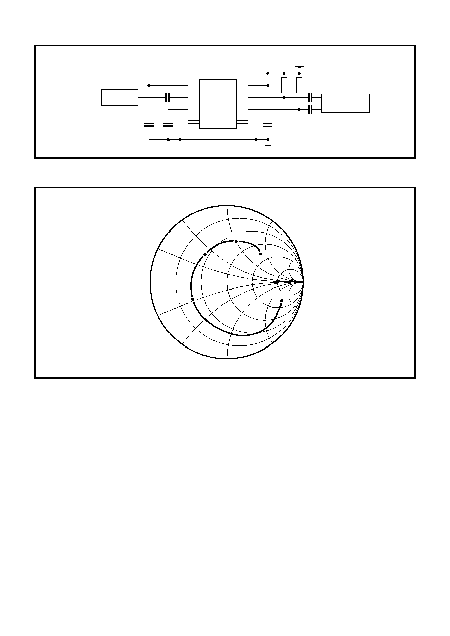
NOTE
1. Measured into 50
measuring instrument in parallel with 50 pullup resistor. See Figure 5.
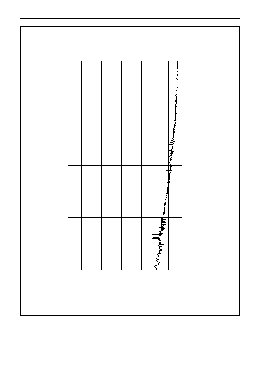
800
600
400
200
V
IN
INT
O
50
(mV RMS)
1
2
3
4
5
6
7
FREQUENCY (GHz)
OPERATING WINDOW
TESTED AS PER
TABLE OF
ELECTRICAL
CHARACTERISTICS
Figure3 Typical input sensitiviy (sinewave drive)
SP8902