The SP8910 is one of a range of very high speed low
power prescalers for professional applications. The
dividing elements are static D type flip flops and therefore
allow operation down to DC if the drive signal is a pulse
waveform with fast risetime. The output stage has
internal100 ohm pull up resistors, giving a 0∑5V p-p output.
If required, an external 100 ohm can be connected in
parallel to give a 50 ohm output.
Features
∑
Very High Operating Speed
∑
Operation down to DC with Square Wave Input
∑
Silicon Technology for Low Phase Noise
(Typically better than 2140dBc/Hz at 1KHz)
∑
5V Single Supply Operation
∑
Low Power Dissipation: 340mW (Typ.)
∑
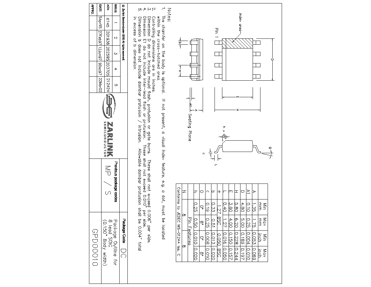
Surface Mount Plastic Package
Absolute Maximum Ratings
Supply voltage, V
CC
Storage temperature
Maximum junction temperature
Prescaler input voltage
Operating temperature
Figure 1 - block diagram
6∑5V
265
∞C to 1150∞C
1150
∞C
2∑5Vp-p
KG240
∞C to 185∞C T
CASE
400
400
V
CC
V
REF
OUTPUT
V
CC
5mA
OUTPUT
OUTPUT
1
8
7
6
2
3
INPUT
INPUT
4
4
100
100
GND
4
5
4
2
SP8910 (MP)
5GHZ
˜
10
Fixed Modulus Divider
Preliminary Information
DS4360
May 2002
Ordering Information
SP8910/KG/MP1S (tubes)
SP8910/KG/MP1T (tape and reel)

2
SP8910
Preliminary Information
Figure 2 - Pin connections - top view
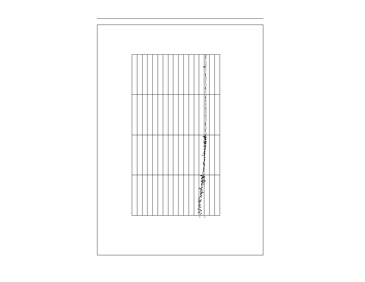
Electrical Characteristics
These characteristics are guaranteed by either production test or design over the following range of operating conditions
unless otherwise stated: T
AMB
= 240
∞C to 185∞C, V
CC
= 4∑75V to 5∑25V
800
600
400
200
V
IN
INT
O 50
(mV RMS)
1
2
3
4
5
6
7
FREQUENCY (GHz)
OPERATING WINDOW
TESTED AS PER
TABLE OF
ELECTRICAL
CHARACTERISTICS
Figure 3 - Typical input sensitiviy (sinewave drive)
1
2
3
4
8
7
6
5
OUTPUT V
CC
OUTPUT
OUTPUT
GND
V
CC
INPUT
INPUT
GND
MP8
SP8910
-
1∑0
1∑0
-
-
440
700
-
218∑0
Characteristic
RMS sinewave
RMS sinewave, T
CASE
= 255
∞C to 185∞C
f
IN
= 1GHz and 4.2GHz
f
IN
= 5GHz
f
IN
= 1GHz and 3GHz
f
IN
= 5.0GHz and 3.8GHz
Into 100
pullup resistor
f
IN
= 1GHz and 5GHz (see note 1 )
92
5∑0
5∑5
180
570
-
-
-
24∑0
Conditions
Pin
1, 8
2, 3
2, 3
2, 3
2, 3
2, 3
2, 3
6, 7
6, 7
Supply current
Input frequency
Input frequency
Input sensitivity
Input sensitivity
Input overload
Input overload
Output voltage
Output power
Typ.
Max.
Min.
Value
Units
mA
GHz
GHz
mVrms
mVrms
mVrms
mVrms
Vp-p
dBm
68
-
-
-
-
-
0∑25
29∑0
NOTE
1. Measured into 50
measuring instrument in parallel with 100 pullup resistor. See Figure 5.