 | –≠–ª–µ–∫—Ç—Ä–æ–Ω–Ω—ã–π –∫–æ–º–ø–æ–Ω–µ–Ω—Ç: ZL10039 | –°–∫–∞—á–∞—Ç—å:  PDF PDF  ZIP ZIP |
Document Outline
- Features
- Applications
- Description
- Figure 1 - Basic Block Diagram
- Figure 2 - Pin Diagram
- Table 1 - Pin Names
- Figure 3 - Detailed Block Diagram
- 1.0 Circuit Description
- 1.1 Functional Description
- 1.2 Signal Path
- 1.2.1 RF Input
- 1.2.2 Baseband
- 1.2.3 RF bypass
- 1.3 Local Oscillator Generation
- 1.3.1 On Chip VCO
- 1.3.2 PLL Frequency Synthesiser
- 1.4 I2C Interface
- 2.0 Register Map and Programming
- Table 2 - Register Map
- 2.1 PLL Registers
- Table 3 - Register 0
- Table 4 - Register 1
- Table 5 - Register 2
- Table 6 - Charge Pump Currents
- Table 7 - PLL Reference Divider Ratios
- Table 8 - Register 3
- 2.2 RF Control Register
- 2.3 Base Band Registers
- Table 10 - Register 5
- Table 11 - Register 6
- Table 12 - Register 7
- Table 13 - BG[3:0] Control of Base Band Post Filter Gain
- 2.4 Local Oscillator Registers
- Table 14 - Register 8
- Table 15 - Register 9
- Table 16 - Register A
- Table 17 - Register B
- Table 18 - Register C
- Table 19 - Register D
- Table 20 - Register E
- 2.5 General Control Register
- Table 21 - Register F
- Table 22 - Output Port States
- 3.0 Applications Information
- Figure 4 - Typical Application with ZL10313 Demodulator
- Table 23 - Typical Performance using ZL10039and ZL10313
- 4.0 Pin Descriptions
- 5.0 Absolute Maximum Ratings
- 6.0 Operating Conditions
- 7.0 Electrical Characteristics
- 8.0 Typical Performance Data
- Figure 5 - Gain v. RFAGC at 25�C
- Figure 6 - Gain v RFAGC v. Temperature
- Figure 7 - IIP3 v Gain at 25�C
- Figure 8 - IIP3 v Gain v Temperature
- Figure 9 - IIP2 v Gain at 25�C
- Figure 10 - IIP2 v Gain v Temperature
- Figure 11 - Noise Figure v Freq at 25�C
- Figure 12 - Noise Figure v RFin v Temperature
- Figure 13 - LO Phase Noise at 25�C
- Figure 14 - LO Phase Noise v Temperature
- Figure 15 - RFin, RF Bypass Return Loss
- Figure 16 - RF Bypass Gain v Temperature
- Figure 17 - Baseband Filter Response 26.5�MHz

1
Zarlink Semiconductor Inc.
Zarlink, ZL and the Zarlink Semiconductor logo are trademarks of Zarlink Semiconductor Inc.
Copyright 2005, Zarlink Semiconductor Inc. All Rights Reserved.
Features
∑ Direct conversion tuner for quadrature down
conversion from L-band to Zero IF
∑ Symbol rate 1-45 MSps
∑ Excellent sensitivity <-84.5 dBm at 27.5 MSps
∑ Independent RF AGC and baseband gain control
∑ Fifth order baseband filters with bandwidth
adjustable from 6 to 43 MHz
∑ Fully integrated alignment-free low phase noise
local oscillator
∑ Selectable RF Bypass
∑ I
2
C compatible control
∑ 3.3 Volt Supply
∑ 28 pin 5x5 mm QFN Package
Applications
∑ DVB-S Free-to-Air Satellite receiver systems
∑ 8PSK Satellite Receiver Systems
Description
The ZL10039 is a fully integrated direct conversion
tuner for digital satellite receiver systems, targeted
primarily at free-to-air DVB-S receivers where high
sensitivity is a priority. The device also contains a RF
Bypass for connecting to a second receiver module.
The ZL10039 is simple to use, requiring no alignment
or tuning algorithms and uses a minimum number of
external components. The device is programmable via
a I
2
C compatible bus.
A complete reference design (ZLE10541) is available
using ZL10313 demodulator.
July 2005
Ordering Information
ZL10039LCG
28 Pin QFN
Trays
ZL10039LCF
28 Pin QFN
Tape and Reel
ZL10039LCG1
28 Pin QFN* Trays
ZL10039LCF1
28 Pin QFN* Tape and Reel
*Pb Free Matte Tin
-10
∞C to +85∞C
ZL10039
Digital Satellite Tuner
with RF Bypass
Data Sheet
Figure 1 - Basic Block Diagram
PLL
I
2
C
Control
Loop
Filter
Z
L103
13
ZL10039
Quadrature
VCO
RF Input
Bypass
Output
I
Q
Crystal
QPSK
De
modulator
RF AGC

ZL10039
Data Sheet
Table of Contents
2
Zarlink Semiconductor Inc.
1.0 Circuit Description. . . . . . . . . . . . . . . . . . . . . . . . . . . . . . . . . . . . . . . . . . . . . . . . . . . . . . . . . . . . . . . . . . . . . . 6
1.1 Functional Description . . . . . . . . . . . . . . . . . . . . . . . . . . . . . . . . . . . . . . . . . . . . . . . . . . . . . . . . . . . . . . . . . 6
1.2 Signal Path . . . . . . . . . . . . . . . . . . . . . . . . . . . . . . . . . . . . . . . . . . . . . . . . . . . . . . . . . . . . . . . . . . . . . . . . . 6
1.2.1 RF Input . . . . . . . . . . . . . . . . . . . . . . . . . . . . . . . . . . . . . . . . . . . . . . . . . . . . . . . . . . . . . . . . . . . . . . . 6
1.2.2 Baseband . . . . . . . . . . . . . . . . . . . . . . . . . . . . . . . . . . . . . . . . . . . . . . . . . . . . . . . . . . . . . . . . . . . . . . 6
1.2.3 RF bypass . . . . . . . . . . . . . . . . . . . . . . . . . . . . . . . . . . . . . . . . . . . . . . . . . . . . . . . . . . . . . . . . . . . . . 7
1.3 Local Oscillator Generation . . . . . . . . . . . . . . . . . . . . . . . . . . . . . . . . . . . . . . . . . . . . . . . . . . . . . . . . . . . . . 7
1.3.1 On Chip VCO . . . . . . . . . . . . . . . . . . . . . . . . . . . . . . . . . . . . . . . . . . . . . . . . . . . . . . . . . . . . . . . . . . . 7
1.3.2 PLL Frequency Synthesiser . . . . . . . . . . . . . . . . . . . . . . . . . . . . . . . . . . . . . . . . . . . . . . . . . . . . . . . . 7
1.4 I2C Interface . . . . . . . . . . . . . . . . . . . . . . . . . . . . . . . . . . . . . . . . . . . . . . . . . . . . . . . . . . . . . . . . . . . . . . . . 8
2.0 Register Map and Programming. . . . . . . . . . . . . . . . . . . . . . . . . . . . . . . . . . . . . . . . . . . . . . . . . . . . . . . . . . . 9
2.1 PLL Registers . . . . . . . . . . . . . . . . . . . . . . . . . . . . . . . . . . . . . . . . . . . . . . . . . . . . . . . . . . . . . . . . . . . . . . 10
2.2 RF Control Register. . . . . . . . . . . . . . . . . . . . . . . . . . . . . . . . . . . . . . . . . . . . . . . . . . . . . . . . . . . . . . . . . . 11
2.3 Base Band Registers. . . . . . . . . . . . . . . . . . . . . . . . . . . . . . . . . . . . . . . . . . . . . . . . . . . . . . . . . . . . . . . . . 12
2.4 Local Oscillator Registers . . . . . . . . . . . . . . . . . . . . . . . . . . . . . . . . . . . . . . . . . . . . . . . . . . . . . . . . . . . . . 13
2.5 General Control Register. . . . . . . . . . . . . . . . . . . . . . . . . . . . . . . . . . . . . . . . . . . . . . . . . . . . . . . . . . . . . . 15
3.0 Applications Information. . . . . . . . . . . . . . . . . . . . . . . . . . . . . . . . . . . . . . . . . . . . . . . . . . . . . . . . . . . . . . . . 16
4.0 Pin Descriptions. . . . . . . . . . . . . . . . . . . . . . . . . . . . . . . . . . . . . . . . . . . . . . . . . . . . . . . . . . . . . . . . . . . . . . . 19
5.0 Absolute Maximum Ratings . . . . . . . . . . . . . . . . . . . . . . . . . . . . . . . . . . . . . . . . . . . . . . . . . . . . . . . . . . . . . 22
6.0 Operating Conditions . . . . . . . . . . . . . . . . . . . . . . . . . . . . . . . . . . . . . . . . . . . . . . . . . . . . . . . . . . . . . . . . . . 22
7.0 Electrical Characteristics . . . . . . . . . . . . . . . . . . . . . . . . . . . . . . . . . . . . . . . . . . . . . . . . . . . . . . . . . . . . . . . 23
8.0 Typical Performance Data. . . . . . . . . . . . . . . . . . . . . . . . . . . . . . . . . . . . . . . . . . . . . . . . . . . . . . . . . . . . . . . 27

ZL10039
Data Sheet
List of Figures
3
Zarlink Semiconductor Inc.
Figure 1 - Basic Block Diagram . . . . . . . . . . . . . . . . . . . . . . . . . . . . . . . . . . . . . . . . . . . . . . . . . . . . . . . . . . . . . . . . 1
Figure 2 - Pin Diagram. . . . . . . . . . . . . . . . . . . . . . . . . . . . . . . . . . . . . . . . . . . . . . . . . . . . . . . . . . . . . . . . . . . . . . . 4
Figure 3 - Detailed Block Diagram . . . . . . . . . . . . . . . . . . . . . . . . . . . . . . . . . . . . . . . . . . . . . . . . . . . . . . . . . . . . . . 5
Figure 4 - Typical Application with ZL10313 Demodulator. . . . . . . . . . . . . . . . . . . . . . . . . . . . . . . . . . . . . . . . . . . 16
Figure 5 - Gain v. RFAGC at 25∞C . . . . . . . . . . . . . . . . . . . . . . . . . . . . . . . . . . . . . . . . . . . . . . . . . . . . . . . . . . . . . 27
Figure 6 - Gain v RFAGC v. Temperature . . . . . . . . . . . . . . . . . . . . . . . . . . . . . . . . . . . . . . . . . . . . . . . . . . . . . . . 27
Figure 7 - IIP3 v Gain at 25∞C . . . . . . . . . . . . . . . . . . . . . . . . . . . . . . . . . . . . . . . . . . . . . . . . . . . . . . . . . . . . . . . . 28
Figure 8 - IIP3 v Gain v Temperature . . . . . . . . . . . . . . . . . . . . . . . . . . . . . . . . . . . . . . . . . . . . . . . . . . . . . . . . . . . 28
Figure 9 - IIP2 v Gain at 25∞C . . . . . . . . . . . . . . . . . . . . . . . . . . . . . . . . . . . . . . . . . . . . . . . . . . . . . . . . . . . . . . . . 29
Figure 10 - IIP2 v Gain v Temperature. . . . . . . . . . . . . . . . . . . . . . . . . . . . . . . . . . . . . . . . . . . . . . . . . . . . . . . . . . 29
Figure 11 - Noise Figure v Freq at 25∞C . . . . . . . . . . . . . . . . . . . . . . . . . . . . . . . . . . . . . . . . . . . . . . . . . . . . . . . . 30
Figure 12 - Noise Figure v RFin v Temperature . . . . . . . . . . . . . . . . . . . . . . . . . . . . . . . . . . . . . . . . . . . . . . . . . . . 30
Figure 13 - LO Phase Noise at 25∞C . . . . . . . . . . . . . . . . . . . . . . . . . . . . . . . . . . . . . . . . . . . . . . . . . . . . . . . . . . . 31
Figure 14 - LO Phase Noise v Temperature . . . . . . . . . . . . . . . . . . . . . . . . . . . . . . . . . . . . . . . . . . . . . . . . . . . . . 31
Figure 15 - RFin, RF Bypass Return Loss . . . . . . . . . . . . . . . . . . . . . . . . . . . . . . . . . . . . . . . . . . . . . . . . . . . . . . . 32
Figure 16 - RF Bypass Gain v Temperature. . . . . . . . . . . . . . . . . . . . . . . . . . . . . . . . . . . . . . . . . . . . . . . . . . . . . . 32
Figure 17 - Baseband Filter Response 26.5 MHz . . . . . . . . . . . . . . . . . . . . . . . . . . . . . . . . . . . . . . . . . . . . . . . . . 33

ZL10039
Data Sheet
4
Zarlink Semiconductor Inc.
Figure 2 - Pin Diagram
Table 1 - Pin Names
Note: Ground contact is via underside of package. Pin 2 is connected to ground internally.
Pin #
Name
Description
Pin #
Name
Description
1
Vvar
LO Tuning Voltage
15
QOUT
Q Channel baseband output
2
PAD/REF
Vvar Reference Ground
/ Continuity Test
16
QOUT
Q Channel baseband output
3
VccVCO
VCO Supply
17
VccBB
Baseband Supply
4
VccLO
LO Supply
18
IOUT
I Channel baseband output
5
LOTEST
LO Test pin - do not connect
19
IOUT
I Channel baseband output
6
RFBYPASS RF Bypass output
20
SLEEP
Hardware power down input
7
VccRF2
RF Supply
21
SCL
I
2
C Clock
8
VccRF1 RF
Supply
22
SDA
I
2
C Data
9
N/C
Not connected
23
P0
General purpose switching output
10
RFIN
RF Input
24
XCAP
Crystal oscillator feedback
11
N/C
Not connected
25
XTAL
Crystal oscillator crystal input
12
N/C
Not connected
26
VccDIG
Digital Supply
13
N/C
Not connected
27
VccCP Varactor
Tuning
Supply
14
RFAGC
RF Gain control input
28
PUMP
PLL charge pump output
Ground - Package Paddle
ZL10039
1
RFAGC
N/C
RFIN
N/C
N/C
N/C
VccRF1
Vvar
PA
D
/
R
E
F
Vc
cVC
O
Vcc
L
O
LOTEST
RFBY
P
A
S
S
VccRF2
SC
L
SDA
P0
XCAP
XTAL
VccDIG
VccCP
PUMP
SL
EE
P
IOUT
IOUT
VccBB
QOU
T
QOU
T

ZL10039
Data Sheet
5
Zarlink Semiconductor Inc.
Figure 3 - Detailed Block Diagram
RFIN
15 BIT
PROGRAMMABLE
DIVIDER
Fpd
CHARGE
PUMP
I2C BUS
INTERFACE
REF
OSC
REFERENCE DIVIDER
Fcomp
SDA
SCL
XTAL
XCAP
PUMP
IOUT
QOUT
RFAGC
PHASE
SPLITTER
VCO
BANK
0 deg
90 deg
P0
RFBYPASS
FILTER
FILTER
BANDWIDTH
ADJUST
LOCK
DETECT
DC
CORRECTION
VccDIG
VccCP
VccBB
VccRF1
VccRF2
VccLO
QOUT
IOUT
LOTEST
PAD/REF
(PADDLE)
SLEEP
DC
CORRECTION
VccVCO
Vvar
LNA
AGC
PORT
INTERFACE
BF

ZL10039
Data Sheet
6
Zarlink Semiconductor Inc.
1.0 Circuit Description
1.1 Functional Description
The ZL10039 is a single chip wide band direct conversion tuner with integral RF bypass optimised for digital
satellite receiver systems. It provides excellent performance in applications where maximum sensitivity is required.
The device offers a highly integrated solution for a satellite tuner incorporating a low phase noise PLL frequency
synthesiser, the quadrature down converter, a fully integrated local oscillator, and programmable baseband channel
filters. A minimal number of additional peripheral components are required. The crystal reference source can be
also used as the reference for the demodulator.
An I
2
C compatible bus interface controls all of the tuner functionality.
The ZL10039 contains both hardware and software power down modes.
1.2 Signal Path
1.2.1 RF Input
The tuner RF input signal at a frequency of 950 ≠ 2150 MHz is fed to the ZL10039 RF input pre-amplifier stage.
The signal handling is designed such that no tracking filter is required to offer immunity to input signal composite
overload.
The RF input amplifier feeds an AGC stage, which provides RF gain control. There is additional gain adjustment in
the baseband section. The total AGC gain range will guarantee an operating dynamic range of ≠92 to ≠10 dBm.
The RF AGC in the ZL10039 is a continually variable gain control stage, and provides the main system AGC set
under control of the analogue AGC signal generated by the demodulator.
The analogue RF AGC is optimised for S/N and S/I performance across the full dynamic range. Typical RF AGC
characteristic and variation of IIP3, IIP2 and NF are shown in Section 8 - Typical Performance Curves.
The output of the AGC stage is coupled to the quadrature mixer where the RF signal is mixed with quadrature local
oscillator signals generated by the on-board local oscillator.
1.2.2 Baseband
The outputs of the quadrature down converter are passed through the baseband filters followed by a programmable
baseband gain stage.
The baseband paths are DC coupled. An integrated DC correction loop prevents saturation due to local oscillator
self-mixing in the converter section. No external components are required for dc correction.
The baseband filters are 5
th
order Chebychev and provide excellent matching in both amplitude and phase
between the I and Q channels. The filters are fully programmable for 3 dB bandwidths from 6 MHz to 43 MHz. The
recommended filter bandwidth is related to the required symbol rate by the following equation.
This equation makes no allowance for LNB tuning offset at low symbol rates < 10MS/s.
The baseband filter uses an automatic tuning algorithm to calibrate the filter bandwidth to the programmed
requirement. This removes any variation due to operating conditions and process variations. The automatic tuning
8
.
0
2
35
.
1
3
◊
◊
=
-
SymbolRate
fc
width
FilterBand
dB

ZL10039
Data Sheet
7
Zarlink Semiconductor Inc.
algorithm uses a frequency locked loop, which locks the filter bandwidth to a reference frequency derived from the
crystal reference input frequency. Further details are provided in the programming section.
The filters are followed by a programmable gain stage. This provides twelve 1.5 dB gain steps. These can be used
for optimising performance at different symbol rates and for adjusting the output level in applications not using
ZL10313.
The differential outputs of each channel stage are designed for low impedance drive capability and low
intermodulation.
1.2.3 RF bypass
The ZL10039 provides a single ended bypass function, which can be used for driving a second receiver module.
The electrical characteristics of the RF input are unchanged whether the RF bypass is enabled or disabled.
The RF Bypass powers up in the enabled state and can also operate with the remainder of the device in power
down modes.
1.3 Local Oscillator Generation
1.3.1 On Chip VCO
The local oscillator on the ZL10039 is fully integrated. It consists of three independently selectable oscillator stages
with sub bands. The three oscillators and sub-bands are designed to provide optimum phase noise performance
over the required tuning range of 950 to 2150 MHz, over operating conditions and process variations.
The local oscillators operate at a harmonic of the required local oscillator frequency and are divided down to the
required LO frequency. The required divider ratio is automatically selected by the local oscillator control logic.
The oscillators are fully controlled by an on-chip automatic tuning algorithm. The user simply programs the required
LO frequency. The control logic automatically selects the required VCO and sub band to give optimum
performance. VCO settling time is minimized as different tuning algorithms are used, depending on the magnitude
of the LO frequency change required. This choice of algorithm is also automatic and does not require user
intervention.
The oscillator control logic tracks any changes in operating conditions and will retune the VCO if necessary,
however hysteresis is built into this function to avoid unnecessary switching.
All oscillator components are included on the chip including the VCO varactor. An external loop filter is required as
part of the PLL frequency synthesiser.
1.3.2 PLL Frequency Synthesiser
The fully integrated PLL frequency synthesiser section controls the LO frequency. The only external requirements
are crystal reference and simple second order loop filter. The PLL can be operated up to comparison frequencies of
2 MHz enabling a wide loop bandwidth for maximizing the close in phase noise performance.
The local oscillator input signal is multiplexed from the active oscillator to an internal preamplifier, which provides
gain and reverse isolation from the divider signals. The output of the preamplifier provides the input to a 15-bit fully
programmable divider with MN+A architecture incorporating a dual modulus 16/17 prescaler.
The output of the programmable divider is fed to the phase comparator where it is compared in both phase and
frequency domain with the comparison frequency. This frequency is derived either from the on-board crystal
controlled oscillator or from an external reference source. In both cases the reference frequency is divided down to
the comparison frequency by the reference divider, which is programmable into 1 of 15 ratios.

ZL10039
Data Sheet
8
Zarlink Semiconductor Inc.
The output of the phase detector feeds a charge pump which combined with an external loop filter integrates the
current pulses to control the varactor voltage. The charge pump current is automatically varied by the VCO control
logic to compensate for VCO gain variations that are dependent on selected sub band. The varactor control voltage
is externally coupled to the oscillator section through the input pin Vvar.
1.4 I
2
C Interface
All programming for the ZL10039 is controlled by an I
2
C data bus and is compatible with 3V3 standard mode
formats.
Data and Clock are fed in on the SDA and SCL lines respectively as defined by I
2
C bus format. The device can
either accept data (write mode), or send data (read mode). The LSB of the address byte (R/W) sets the device into
write mode if it is logic `0', and read mode if it is logic `1'. The I
2
C address is fixed at C0 (Write)/C1(Read) in hex
format.
The ZL10039 contains 16 control registers. These registers are read/write registers. These registers are addressed
as sub-addresses on the I
2
C bus. Registers can be addressed as random access single write/read or random
access sequential write and read as shown below.
Random Access Single Write
Random Access Sequential Write
Stop
Random Access Single Read
Random Access Sequential Read
W
Write bit
A
Acknowledge Bit
N
Not Acknowledge
A SLEEP pin is provided. This powers down all sections of the chip including the crystal oscillator and I
2
C interface.
The RF bypass function will be operational in this mode providing it has been previously enabled through the I
2
C
interface.
Stop
Start
Device
Address
W A
Register
Address
N
A
Register
Data
N
A
Stop
Stop
Start
Device
Address
W A
Register
Address
N
A
Register
Data
N
A
Register
Data
N+1
...
Register
Data
N+M
A
Stop
Stop
Start
Device
Address
W A
Register
Address
N
A
Start
Device
Address
R A
Register
Data
N
N Stop
Stop
Start
Device
Address
W A
Register
Address
N
A
Start
Device
Address
R A
Register
Data
N
A
...
Register
Data
N+M
N Stop

ZL10039
Data Sheet
9
Zarlink Semiconductor Inc.
2.0 Register Map and Programming
The register map is arranged as 16 byte-wide read/write registers grouped by functional block. The registers may
be written to and read-back from either sequentially (for lowest overhead) or specifically (for maximum flexibility).
A significant number of bits are used for test and evaluation purposes only and are fixed at logic `0' or `1'. The
correct programming for these test bits is shown in the table below. It is essential that these values are programmed
for correct operation. When the contents of the registers are read back the value of some bits may have changed
from their programmed value. This is due to the internal automatic control which can update registers. Any changes
can be ignored.
Read only bits are marked with an asterisk (*). Any data written to these bits will be ignored.
Registers are set to default settings on applying power. These conditions are shown below and in the applicable
tables.
X* denotes a read only test bit
Register
Block
Function
0
PLL
PLF
2
14
2
13
2
12
2
11
2
10
2
9
2
8
1
PLL
2
7
2
6
2
5
2
4
2
3
2
2
2
1
2
0
2
PLL
0
0
C1
C0
R3
R2
R1
R0
3
PLL
X*
1
0
0
0
0
0
0
4
RF Front End
X*
1
1
0
1
1
LEN
0
5
Base Band
BF7
BF6
BF5
BF4
BF3
BF2
BF1
BF0
6
Base Band
0
LF
SF
BR4
BR3
BR2
BR1
BR0
7
Base Band
BLF*
BG3
BG2
BG1
BG0
0
0
0
8
Local Oscillator
FLF*
0
1
0
0
0
0
0
9
Local Oscillator
1
0
1
0
0
0
1
0
A
Local Oscillator
1
1
1
1
0
0
0
1
B
Local Oscillator
X*
X*
1
1
1
0
0
0
C
Local Oscillator
1
1
0
1
0
0
0
0
D
Local Oscillator
X*
X*
X*
1
0
0
0
0
E
Local Oscillator
X*
X*
1
1
0
0
0
0
F
General
PD
CLR
P0
0
ZI3*
ZI2*
ZI1*
ZI0*
Table 2 - Register Map

ZL10039
Data Sheet
10
Zarlink Semiconductor Inc.
2.1 PLL Registers
There are four registers that control the PLL:
The PLF bit is the PLL lock detect circuit output. The PLF bit is set after 64 consecutive comparison cycles in lock.
A chip-wide reset initializes the lock detect output to 0.
The 2[
14:8
] bits are the MSB bits of the LO Divider divide value.
The 2[
7:0
] bits are the LSB bits of the LO Divider divide value. The division ratio of the LO divider is fully
programmable to integer values within the range of 240 to 32767.
Note that when the LO Divider divide value is to be changed, the new value is not actually presented to the LO
Divider until all of the 15-bit control word 2[
14:0
] has been programmed. Register 0 and 1 must be therefore be
programmed (in any order) before the LO divider is updated even if the only data change is in one of the registers.
The C[1:0] bits set the programmed charge pump current
.
The charge pump current is automatically increased to the next setting dependent on the VCO sub band that has
been selected by the VCO tuning algorithm. This is to compensate for changes in VCO gain and so provide
consistent PLL performance across all sub bands. Programming the highest charge pump value will not allow the
value to be incremented, therefore this value should not be programmed.
The value read back for the charge pump current is the actual value in use for the selected sub band.
Bit Field
Name
Default
Type
Description
7
PLF
-
R
PLL Lock Flag
6:0
2
[14:8]
0
R/W
MSB bits of LO Divider register
Table 3 - Register 0
Bit Field
Name
Default
Type
Description
7:0
2
[7:0]
0
R/W
LSB bits of LO Divider register
Table 4 - Register 1
Bit Field
Name
Default
Type
Description
7:6
-
0
R/W
Test modes
5:4
C[1:0]
0
R/W
Charge pump current
3:0
R[3:0]
0
R/W
Reference divider ratio
Table 5 - Register 2
C[1]
C[0]
Typ
Units
0
0 400
uA
0
1
550
uA
1
0
750
uA
1
1
1000
uA
Table 6 - Charge Pump Currents

ZL10039
Data Sheet
11
Zarlink Semiconductor Inc.
The R[3:0] bits select the Reference Divider divide ratio. The ratio selected is not a simple binary power-of-two
value but through a lookup table, see Table 7- PLL Reference Divider Ratios.
This register controls test modes within the PLL. This should be programmed with the default settings.
2.2 RF Control Register
A single register controls RF programmability.
R3
R2
R1
R0
Division
Ratio
0
0
0
0
2
0
0
0
1
4
0
0
1
0
8
0
0
1
1
16
0
1
0
0
32
0
1
0
1
64
0
1
1
0
128
0
1
1
1
256
1
0
0
0
3
1
0
0
1
5
1
0
1
0
10
1
0
1
1
20
1
1
0
0
40
1
1
0
1
80
1
1
1
0
160
1
1
1
1
320
Table 7 - PLL Reference Divider Ratios
Bit Field
Name
Default
Type
Description
7:0
-
0X40
R/W
Test Modes
Table 8 - Register 3
Bit Field
Name
Default
Type
Description
7
-
-
R
Test Modes
6:2
-
11011
R/W
Test Modes
1
LEN
1
R/W
Bypass Enable
0
-
0
R/W
Not used
Table 9 - Register 4

ZL10039
Data Sheet
12
Zarlink Semiconductor Inc.
The LEN bit enables the RFBYPASS output. With this bit set, the RF Bypass is active even if `software' or
`hardware' power down has been selected.
2.3 Base Band Registers
There are three registers that control the Base Band:
The bits BF[7:0] control the bandwidth of the baseband filter. An automatic adjustment routine synchronizes the
filter bandwidth to a reference frequency derived from the crystal.
The LF and SF bits disable the baseband filter adjustment. It is recommended that these bits are set after
programming the filter bandwidth to prevent interactions within the circuit. These bits must be reset to enable the
baseband filter bandwidth to be reprogrammed.
The BR[4:0] bits set the crystal reference divide ratio. This effectively determines the resolution setting of the
baseband filters. The baseband filter settings (BF[7:0]) can be calculated from the following equation.
See Section 3 Applications Information, for a typical programming example.
BR[4:0] = 0 is invalid
The BLF bit indicates that the baseband adjustment has completed and locked.
The control bits BG[3:0] define the gain of the Base Band post-filter amplifier. The following table shows the gain -
note this is relative gain. The 1.5 dB gain steps enable the baseband output level to be adjusted and optimise gain
distribution for different symbol rates.
Bit Field
Name
Default
Type
Description
7:0
BF[7:0]
0X3C
R/W
Base Band Filter Cut-Off Frequency
Table 10 - Register 5
Bit Field
Name
Default
Type
Description
7
-
0
R/W
Test Mode
6
LF
0
R/W
Baseband Filter Adjust Disable
5
SF
0
R/W
Baseband Filter Adjust Disable
4:0
BR[4:0]
1000
R/W
Base Band Reference Division Ratio
Table 11 - Register 6
Bit Field
Name
Default
Type
Description
7
BLF
-
R
Base Band Lock Flag
6:3
BG[3:0]
0111
R/W
Base Band Gain Select
2:0
-
000
R/W
Test Modes
Table 12 - Register 7
1
(
-
=
(MHz)
Frequency
Crystal
0])
:
BR[4
*
5.088
*
(MHz)
bandwidth
Filter
0]
:
BF[7

ZL10039
Data Sheet
13
Zarlink Semiconductor Inc.
2.4 Local Oscillator Registers
There are seven registers that control the Local Oscillator: These are used primarily for test and evaluation by
Zarlink Semiconductor. Although VCO's can be manually programmed, the user is recommended to use the default
automatic settings as these provide optimum performance.
The FLF bit is the VCO tuning controller lock output and is set when PLL is locked and the automatic VCO tuning is
optimised and complete.
Register 9 to Register E are for test modes only. It is however important that these registers are programmed with
the values shown.
BG[3]
BG[2]
BG[1]
BG[0]
Gain (dB)
0
0
0
0
0
0
0
0
1
1.5
0
0
1
0
3.0
0
0
1
1
4.5
0
1
0
0
6.0
0
1
0
1
7.5
0
1
1
0
9.0
0
1
1
1
10.5
1
0
0
0
12.0
1
0
0
1
13.5
1
0
1
0
15.0
1
0
1
1
16.5
Table 13 - BG[3:0] Control of Base Band Post Filter Gain
Bit Field
Name
Default
Type
Description
7
FLF
-
R
Full Lock Flag
6:0
-
0X20
R/W
Test Modes
Table 14 - Register 8

ZL10039
Data Sheet
14
Zarlink Semiconductor Inc.
Chip Level Control Register
Bit Field
Name
Default
Type
Description
7:0
-
0XA2
R/W
Test Modes
Table 15 - Register 9
Bit Field
Name
Default
Type
Description
7:0
-
0XF1
R/W
Test Modes
Table 16 - Register A
Bit Field
Name
Default
Type
Description
7:6
-
-
R
Test Modes (read only)
5:0
-
0X38
R/W
Test Modes
Table 17 - Register B
Bit Field
Name
Default
Type
Description
7:0
-
0XD0
R/W
Test Modes
Table 18 - Register C
Bit Field
Name
Default
Type
Description
7:5
-
-
R
Test Modes (read only)
4:0
-
0X10
R/W
Test Modes
Table 19 - Register D
Bit Field
Name
Default
Type
Description
7:6
-
-
R
Test Modes (read only)
5:0
-
0X30
R/W
Test Modes
Table 20 - Register E

ZL10039
Data Sheet
15
Zarlink Semiconductor Inc.
2.5 General Control Register
This register controls powerdown and general control functions:
The PD bit is the `software' power down control. When this bit is set to 1, all the analogue blocks are powered down
with the exception of the Crystal Oscillator. The I
2
C interface will remain active and can still be used to enable the
RF Bypass.
Setting the SLEEP input pin high also invokes `software' power down with the addition of powering down the Crystal
Oscillator to produce `hardware' power down. The RF Bypass will remain active if it has been previously
programmed on the I
2
C bus. Note that in `hardware' power down, the I
2
C interface does not operate.
The CLR bit re-triggers the power-on-reset function. This resets all register values to their power-on reset default
value. The CLR bit is itself cleared. Note that the chip-wide reset will reset the I
2
C Interface and the current write
sequence used to set this bit will not be acknowledged.
The P0 bit controls the state of the output port according to Table 22.
Bit Field
Name
Default
Type
Description
7
PD
1
R/W
Power Down
6
CLR
0
R/W
Clear and reset logic
5
P0
0
R/W
Port 0 control
4
-
0
R/W
Test Mode
3:0
ZI3:0-
-
R
Zarlink identity code (read only)
Table 21 - Register F
P0
Output Port State
0
Off, high impedance
1
On, current sinking
Table 22 - Output Port States

ZL10039
Data Sheet
16
Zarlink Semiconductor Inc.
3.0 Applications Information
Figure 4 - Typical Application with ZL10313 Demodulator
ZL10039
Data Sheet
17
Zarlink Semiconductor Inc.
Figure 4 shows a typical application using a ZL10313 as a demodulator. This is available as a reference design
(ZLE10541) from Zarlink Semiconductor.
The design uses a standard two layer board. All components are mounted on the upper surface with the lower
surface as a ground plane. The RF input does not require any external matching components although a coupling
capacitor is required. The RF bypass output requires a series inductor for optimum matching. Good decoupling
should be used - these components should be mounted as close to the device as practicable.
All ground contact to the ZL10039 is to the ground `paddle' on the underside of the package. This must be soldered
fully to the board to achieve best thermal and electrical contact. It is recommended that an array of vias (4 x 4) is
used to achieve good contact to the ground plane underneath the device
A common crystal reference can be used for the tuner and demodulator. The crystal oscillator capacitors are
optimised for a 10.111 MHz reference.
Sensitivity is optimised by minimizing interaction from digital signal activity in the demodulator. This is achieved by
filtering in the agc control, and filter networks in the baseband I and Q signals between the demodulator and
ZL10039. These networks should be mounted as close to the ZL10039 as possible.
The typical performance from the reference design is shown in the table below:
Further information is provided in ZLE10541 user guides.
Parameter
Typ.
Units
Notes
Sensitivity
dBm
QEF 27.5MS/s rate 7/8
No added noise
C/N 27.5MS/s rate 7/8
2e-4 post Viterbi BER
8.2
8.1
8.1
dB
dB
dB
Input = -69 dBm
-45 dBm
-23 dBm
C/N 2MS/s rate 7/8
2e-4 post Viterbi BER
8.1
8.0
8.0
dB
dB
dB
Input = -81dBm
-45 dBm
-23 dBm
Interference Rejection Ratio
27.5 MS/s rate 7/8.
Interferers at -25 dBm
32
35
45
dB
dB
dB
N+1
N+4
N+10
Table 23 - Typical Performance using ZL10039and ZL10313

ZL10039
Data Sheet
18
Zarlink Semiconductor Inc.
The bandwidth of the baseband filter is given by the following expression:
Equation 1
where:
fbw
=
the filter bandwidth in MHz within the range 8 MHz to 43 MHz.
fxtal
=
crystal oscillator frequency in MHz.
BR
=
decimal value of the bits BR[4:0], range 1-31.
(BR = 0 is not allowed)
BF
=
decimal value of the register bits BF[7:0], range 0 - 255.
The above equation can be re-arranged as follows
Equation 2
It is recommended that BR should be set so that
is approximately 1 MHz
This sets the bandwidth resolution to approximately 200kHz
The value of BF can now be calculated from Equation 2 and rounded to the nearest integer:
Example
Conditions: fxtal = 10.111 MHz, fbw = 26.5 MHz
Choose BR = 10
BF = 132
The actual filter bandwidth is therefore given by:
(
)
1
BF
x
5.088
x
BR
fxtal
fbw
+
=
1
fxtal
BR
x
5.088
fbw x
BF
-
=
BR
fxtal
132.35
1
10.111
10
x
5.088
x
26.5
BF
=
-
=
(
)
MHz
43
26
5.088
1
x
1
132
x
10
10.111
fbw
.
=
+
=

ZL10039
Data Sheet
19
Zarlink Semiconductor Inc.
4.0 Pin Descriptions
Pin#
Name
Description
Schematic
1
Vvar
LO voltage tuning input.
2
PAD/REF
Bonded to paddle. Production
continuity test for paddle soldering
and also ground reference for loop
filter.
3
VccVCO
+3.3 V voltage supply for VCO's.
4
VccLO
+3.3 V voltage supply for LO circuits.
5
LOTEST
For Zarlink testing only.
Must not connect.
6
RFBYPASS
RF bypass output. AC couple.
Matching circuitry as shown in
applications diagram.
Do not connect in applications where
RF bypass is not required.
7
VccRF2
+3.3 V voltage supply for RF.
8
VccRF1
+3.3 V voltage supply for RF.
9
N/C
Not connected.
10
RFIN
RF input. AC couple.
See applications diagram.
11
N/C
Not connected.
12
N/C
Not connected.
13
N/C
Not connected.
Vvar
100
Vbias
Components
per VCO
120
RFBYPASS
RFIN
Vcc

ZL10039
Data Sheet
20
Zarlink Semiconductor Inc.
14
RFAGC
RF analog gain control input.
15
16
QOUT
QOUT
Q channel baseband differential
outputs.
AC couple as shown in application
diagram.
17
VccBB
+3.3 V voltage supply for Baseband.
18
19
IOUT
IOUT
I channel baseband differential
outputs.
AC couple as shown in application
diagram.
Same as pin 15,16
20
SLEEP
Hardware power down input.
Logic '0' normal mode.
Logic '1' - analog sections are
powered down including crystal
oscillator.
21
SCL
I
2
C serial clock input
Pin#
Name
Description
Schematic
RFAGC
Vcc
10k
30k
Vref
Output
Vcc
SLEEP
CMOS Digital input
SCL
CMOS Digital input

ZL10039
Data Sheet
21
Zarlink Semiconductor Inc.
22
SDA
I
2
C serial data input/output
23
P0
Switching port output.
Open Drain
'0' = disabled (high impedance)
'1' = enabled.
24
25
XCAP
XTAL
Reference oscillator crystal inputs.
XTAL pin can be used for external
reference via 10nF capacitor.
See applications diagram for
recommended external components
(10.111 MHz)
26
VccDIG
+3.3 V voltage supply for digital logic.
27
VccCP
+3.3 V voltage supply for varactor
tuning.
28
PUMP Charge
pump
output.
Pin#
Name
Description
Schematic
SDA
CMOS Digital input/output
P0
CMOS Digital output
XCAP
0.2 mA
XTAL
100
Vcc
PUMP
Vcc

ZL10039
Data Sheet
22
Zarlink Semiconductor Inc.
5.0 Absolute Maximum Ratings
6.0 Operating Conditions
Parameter
Min.
Max.
Units
Notes
Maximum voltage on any Vcc
pin
-0.3
3.6
V
Maximum voltage between
any two Vcc pins
0.3
V
Maximum voltage on any
other pin
-0.3
Vcc + 0.3
V
The voltage on any pin must
not exceed 3.6 V
P0 Output current
20
mA
Maximum RF Input
10
dBm
Storage temperature
-55
150
∞C
Junction temperature
125
∞C
Package thermal resistance
34
∞C/W
Package ground paddle
soldered to ground
ESD Protection
1.75
kV
Mil std 883B method 3015
cat1
Parameter
Min.
Max.
Units
Notes
Supply Voltage
3.15
3.45
V
Operating Temperature
-10
+85
∞C
RF Input Frequency
950
2150
MHz
Baseband I/Q Output load
4.7
15
k
pF

ZL10039
Data Sheet
23
Zarlink Semiconductor Inc.
7.0 Electrical Characteristics
Test conditions (unless otherwise stated)
T
amb
= 25
o
C, Vee= 0V, All Vcc supplies = 3.3 V+-5%
Baseband Gain = 9 dB
Baseband filter bandwidth 26.5 MHz
All power levels are referred to 75
(0 dBm = 109 dBµV)
Specifications refer to total cascaded system of converter/AGC stage and baseband amplifier/filter stage.
Output amplitude of 0.5 Vp-p differential.
Characteristic
Min.
Typ.
Max.
Units
Conditions
Supply Current
145
155
200
215
mA
mA
Outputs unloaded. Max Filter bandwidth
RF Bypass disabled
RF Bypass enabled
Hardware Power Down
Software Power Down
0.2
1.7
3
mA
mA
No RF input.
Crystal oscillator remains operational
System
Input Return Loss
7
9
dB
Zo = 75
. Bypass enabled or disabled
Noise Figure DSB
6
7
9
10
13
dB
dB
dB
At max gain
At -70 dBm operating level
At -60 dBm operating level
Variation in NF with RF
gain adjust
-1
dB/dB
Above -60dBm operating level
Operating dynamic range
-92
-10
dBm
1MS/s
Operating dynamic range
-84
-10
dBm
27.5MS/s
Conversion Gain
Max
Min
72
78
-10
10
dB
dB
RFagc = 0.2V
RFagc = 2.8V
AGC Control Range
68
72
dB
AGC monotonic for RFagc from Vee to
Vcc
RFAGC input current
-150
150
µA
Vee <= RFagc<= Vcc
System IM2
-23
-30
dBc
dBc
Baseband defined, note 1
RF front-end defined, note 2
System IM3
-26
-38
dBc
dBc
Note 3
Note 4
IIP2
5
dBm
At -25 dBm input, note 2
IIP3
-5
dBm
At -25 dBm input, note 3

ZL10039
Data Sheet
24
Zarlink Semiconductor Inc.
Variation in system
second order
intermodulation intercept
-1
dB/dB
Note 5
Variation in system third
order intermodulation
intercept
-1
dB/dB
Note 6
LO second harmonic
interference level
-50
-35
dBc
Note 7, all gain settings
Quadrature gain match
-1
1
dB
1.5 to 18 MHz
Quadrature phase match
-3
-5
3
5
deg
deg
Baseband Signal = 1.5 MHz
Baseband Signal = 18 MHz
I & Q channel in band
ripple
1
dB
1.5 to 18 MHz
LO reference sideband
spur level on I & Q outputs
-40
dBc
Synthesiser phase detector comparison
frequency 500 - 2000 kHz
In band local oscillator
leakage to RF input
-65
-55
dBm
dBm
950 - 2150 MHz
30 - 950 MHz
Channel lock time
50
ms
Worst case channels
Local Oscillator
VCO Gain
27
MHz/V
LO = 2 GHz. Note 8
SSB Phase Noise
-83
-76
-96
-110
dBc/Hz
dBc/Hz
dBc/Hz
10 kHz offset
100 kHz offset
1 MHz offset
Phase Noise floor
-132
dBc/Hz
Integrated phase jitter
3
deg
10 kHz to 15 MHz
Varactor input current
-10
10
nA
Vvar = 0.5 to 1.3 V
Baseband Filters
Bandwidth
6
43
MHz
Max specified load
Bandwidth Tolerance
-1
+1
MHz
All bandwidth settings
Time to change filter
bandwidth
10
ms
Total Harmonic Distortion
-30
dBc
1 Vpp differential output at 43 MHz filter
bandwidth
RF Bypass
Output load = 75 ohms
Gain
-2
1.5
6
dB
Noise Figure
10
dB
OPIP3
5
dB
Note 9
OPIP2
10
dBm
Note 10
Characteristic
Min.
Typ.
Max.
Units
Conditions

ZL10039
Data Sheet
25
Zarlink Semiconductor Inc.
Output return loss
9
dB
Forward Isolation
25
dB
950-2150 MHz. Bypass disabled
Reverse Isolation
25
dB
950-2150 MHz. Bypass enabled or
disabled
In band LO leakage
-65
dBm
950-2150 MHz. Bypass enabled or
disabled
Synthesiser
Charge Pump Current
304
422
578
762
400
550
750
1000
552
759
1035
1380
µA
µA
µA
µA
Charge Pump Matching
2
%
Vpin = 0.5 to 1.3 V
Charge Pump Leakage
-10
+/-3
+10
nA
Vpin = 0.5 to 1.3 V
Charge Pump Compliance
0.4
Vcc
- 0.4
V
Crystal Frequency
4
20
MHz
Recommended crystal
series resistance
12
25
50
ohms
10 MHz crystal
Crystal power dissipation
100
500
µW
Note 11
Crystal load capacitance
16
pF
Note 11
Crystal oscillator startup
time
10
ms
External reference input
frequency
4
20
MHz
ac coupled sinewave
External reference drive
level
0.5
2.0
Vpp
ac coupled sinewave
Phase detector
comparison frequency
0.5
2
MHz
Equivalent phase noise at
phase detector
-148
dBc/Hz
10 MHz crystal SSB within PLL loop
bandwidth
Interface
SDA, SCL
Input high voltage
Input low voltage
Hysteresis
Input current
2.3
0
-10
0.4
3.6
1
10
V
V
µA
Input = Vee to VccDIG +0.3 V
SDA Output Voltage
0.4
V
Isink = 3 mA
SCL clock rate
100
kHz
Characteristic
Min.
Typ.
Max.
Units
Conditions

ZL10039
Data Sheet
26
Zarlink Semiconductor Inc.
Note 1: AGC set to deliver an output of 0.5 Vp-p with an input CW @ frequency fc of -25 dBm, undesired tones at fc+146 and
fc+155 MHz @ -18 dBm, generating output IM spur at 9 MHz. Measured relative to unwanted signal.
Note 2: LO set to 2145 MHz and AGC set to deliver a 5 MHz output of 0.5 Vp-p with an input CW @ frequency 2150 MHz of ≠25 dBm.
Undesired tones at 1.05 and 1.1 GHz at -25 dBm generating IM spur at 5 MHz baseband. Measured relative to unwanted
signal.
Note 3: AGC set to deliver an output of 0.5 Vp-p with an input CW @ frequency fc of -25 dBm. Two undesired tones at fc+205 and
fc+405 MHz at -18 dBm, generating output IM spur at 5 MHz.
Note 4: AGC set to deliver an output of 0.5 Vp-p with an input CW @ frequency fc of -25 dBm. Two undesired tones at fc+205 and
fc+405 MHz at -24 dBm, generating output IM spur at 5 MHz.
Note 5: Two undesired tones at 1.05 and 1.1 GHz at 0 dBc relative to desired at 2.15 GHz, Local oscillator tuned to 2.145 GHz with
AGC set to deliver 0.5 Vp-p differential on desired signal. Desired input signal is varied from -25 dBm to -75 dBm.
Note 6: Two undesired tones at fc+55 and fc+105 MHz at 7 dBc relative to desired at fc converted to 5 MHz baseband with local
oscillator tuned to fc GHz with AGC set to deliver 0.5 Vp-p differential on desired signal. Desired input signal is varied from
-30 dBm to -75 dBm, with the undesired amplitude capped at -25 dBm.
Note 7: The level of 2.01 GHz down converted to baseband relative to 1.01 GHz with the oscillator tuned to 1 GHz.
Note 8: Reference VCO gain value for loop filter calculations. Using this recommended value then takes into account VCO switching
and automatic charge pump current variations.
Note 9: Two input tones at fc+50 and fc+100 MHz at -18 dBm, generating output IM product at fc.
Note 10: IM2 product from two input tones at 1.05 and 1.1 GHz at -18 dBm, generating IM product at 2150 MHz.
Note 11: Crystal specifications vary considerably and significantly effect the choice of external oscillator capacitor values. Each
application may require separate consideration for optimum performance.
External Port P0
Sink Current
Leakage Current
3
10
mA
µA
Vo = 0.7 V
Vo = Vcc
SLEEP Input
Input high voltage
Input low voltage
Input Current
1.9
Vee
3.6
1.0
10
V
V
µA
Vin = Vee to VccDIG
Characteristic
Min.
Typ.
Max.
Units
Conditions
ZL10039
Data Sheet
27
Zarlink Semiconductor Inc.
8.0 Typical Performance Data
Figure 5 - Gain v. RFAGC at 25∞C
Figure 6 - Gain v RFAGC v. Temperature
-20
-10
0
10
20
30
40
50
60
70
80
0
0.5
1
1.5
2
2.5
3
AGC Voltage
C
onversion gain dB
LO 920MHz
LO 1550MHz
LO 2150MHz
-20
-10
0
10
20
30
40
50
60
70
80
0
0.5
1
1.5
2
2.5
3
AGC Voltage
Conversion gain dB
+90∞C
+25∞C
-15∞C

ZL10039
Data Sheet
28
Zarlink Semiconductor Inc.
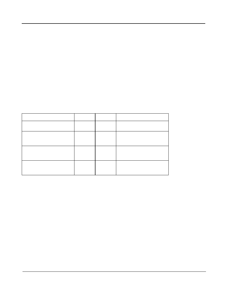
Figure 7 - IIP3 v Gain at 25∞C
Figure 8 - IIP3 v Gain v Temperature
-60
-50
-40
-30
-20
-10
0
10
20
20
30
40
50
60
70
80
Gain Setting dB
IIP
3
dBm
Spec
3.1Vcc
3.3Vcc
3.5Vcc
-60
-50
-40
-30
-20
-10
0
10
20
20
30
40
50
60
70
80
Gain Setting dB
IIP
3
dBm
Spec
+90∞C
+25∞C
-15∞C

ZL10039
Data Sheet
29
Zarlink Semiconductor Inc.
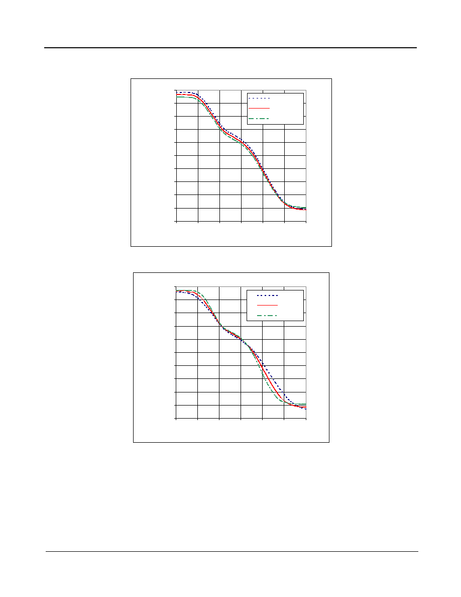
Figure 9 - IIP2 v Gain at 25∞C
Figure 10 - IIP2 v Gain v Temperature
-50
-40
-30
-20
-10
0
10
20
30
40
20
30
40
50
60
70
80
Gain Setting dB
IIP2
dBm
Spec
3.1Vcc
3.3Vcc
3.5Vcc
-50
-40
-30
-20
-10
0
10
20
30
40
20
30
40
50
60
70
80
Gain Setting dB
IIP2
dBm
Spec
+90∞C
+25∞C
-15∞C

ZL10039
Data Sheet
30
Zarlink Semiconductor Inc.
Figure 11 - Noise Figure v Freq at 25∞C
Figure 12 - Noise Figure v RFin v Temperature
5
5.5
6
6.5
7
7.5
8
8.5
9
9.5
10
950
1150
1350
1550
1750
1950
2150
Frequency (MHz)
NF (dB)
0
10
20
30
40
50
-80
-70
-60
-50
-40
-30
-20
-10
RFin (dBm)
NF (dB)
-15C
25C
90C
Spec

ZL10039
Data Sheet
31
Zarlink Semiconductor Inc.
Figure 13 - LO Phase Noise at 25∞C
Figure 14 - LO Phase Noise v Temperature
-130
-120
-110
-100
-90
-80
-70
10000
100000
1000000
10000000
Frequency offset (Hz)
Ph
ase No
i
se (d
Bc/
H
z)
-120.0
-115.0
-110.0
-105.0
-100.0
-95.0
-90.0
-85.0
-80.0
1000
10000
100000
1000000
Frequency offset (Hz)
Ph
ase n
o
i
se (
d
B
c
/H
z)
-15degC
+90degC

ZL10039
Data Sheet
32
Zarlink Semiconductor Inc.
Figure 15 - RFin, RF Bypass Return Loss
Figure 16 - RF Bypass Gain v Temperature
-30.0
-25.0
-20.0
-15.0
-10.0
-5.0
0.0
950
1150
1350
1550
1750
1950
2150
Frequency (MHz)
Return Loss (dB)
s11 RFBYPASS on
s22 RFBYPASS on
-1.0
-0.5
0.0
0.5
1.0
1.5
2.0
2.5
3.0
950
1150
1350
1550
1750
1950
2150
Frequency (MHz)
Gain
(d
B)
-15C
+25C
+90C
ZL10039
Data Sheet
33
Zarlink Semiconductor Inc.
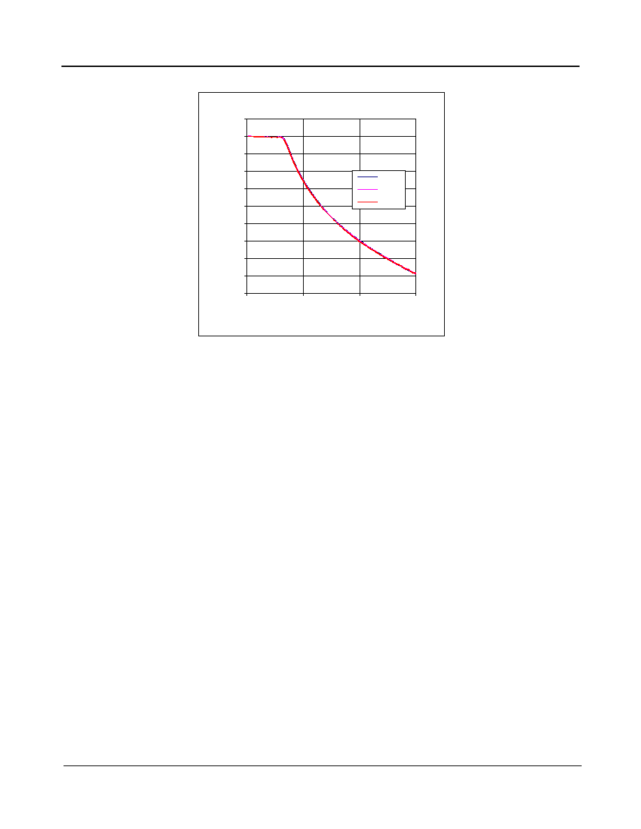
Figure 17 - Baseband Filter Response 26.5 MHz
26.5MHz filter response
-90
-80
-70
-60
-50
-40
-30
-20
-10
0
10
0
40
80
120
Baseband frequency (MHz)
No
rmalised
amp
litu
d
e
(d
B)
+90∞C
+25∞C
-15∞C

Previous package codes
Package Code
ACN
DATE
ISSUE
APPRD.
c Zarlink Semiconductor 2005 All rights reserved.
1
CDCA
10June05
LH
LC
Package Outline for 28 Lead QFN (5 x 5mm)
112083
Full Connectiing Bar (FCB), VHHD-3 variant

www.zarlink.com
Information relating to products and services furnished herein by Zarlink Semiconductor Inc. or its subsidiaries (collectively "Zarlink") is believed to be reliable.
However, Zarlink assumes no liability for errors that may appear in this publication, or for liability otherwise arising from the application or use of any such
information, product or service or for any infringement of patents or other intellectual property rights owned by third parties which may result from such application or
use. Neither the supply of such information or purchase of product or service conveys any license, either express or implied, under patents or other intellectual
property rights owned by Zarlink or licensed from third parties by Zarlink, whatsoever. Purchasers of products are also hereby notified that the use of product in
certain ways or in combination with Zarlink, or non-Zarlink furnished goods or services may infringe patents or other intellectual property rights owned by Zarlink.
This publication is issued to provide information only and (unless agreed by Zarlink in writing) may not be used, applied or reproduced for any purpose nor form part
of any order or contract nor to be regarded as a representation relating to the products or services concerned. The products, their specifications, services and other
information appearing in this publication are subject to change by Zarlink without notice. No warranty or guarantee express or implied is made regarding the
capability, performance or suitability of any product or service. Information concerning possible methods of use is provided as a guide only and does not constitute
any guarantee that such methods of use will be satisfactory in a specific piece of equipment. It is the user's responsibility to fully determine the performance and
suitability of any equipment using such information and to ensure that any publication or data used is up to date and has not been superseded. Manufacturing does
not necessarily include testing of all functions or parameters. These products are not suitable for use in any medical products whose failure to perform may result in
significant injury or death to the user. All products and materials are sold and services provided subject to Zarlink's conditions of sale which are available on request.
Purchase of Zarlink's I
2
C components conveys a licence under the Philips I
2
C Patent rights to use these components in and I
2
C System, provided that the system
conforms to the I
2
C Standard Specification as defined by Philips.
Zarlink, ZL and the Zarlink Semiconductor logo are trademarks of Zarlink Semiconductor Inc.
Copyright Zarlink Semiconductor Inc. All Rights Reserved.
TECHNICAL DOCUMENTATION - NOT FOR RESALE
For more information about all Zarlink products
visit our Web Site at