1
Zarlink Semiconductor Inc.
Zarlink, ZL and the Zarlink Semiconductor logo are trademarks of Zarlink Semiconductor Inc.
Copyright 2003-2005, Zarlink Semiconductor Inc. All Rights Reserved.
Features
General
� Circuit Emulation Services over Packet (CESoP)
transport for MPLS, IP and Ethernet networks
� On chip timing & synchronization recovery across
a packet network
� Grooming capability for Nx64 Kbps trunking
Circuit Emulation Services
� Complies with ITU-T recommendation Y.1413
� Complies with IETF PWE3 draft standards for
CESoPSN and SAToP
� Complies with CESoP draft IAs for MEF and MFA
� Structured, synchronous CESoP with clock
recovery
� Unstructured, asynchronous CESoP, with integral
per stream clock recovery
TDM Interfaces
� Up to 32 T1/E1, 8 J2, 2 T3/E3 or 1 STS-1 ports
� H.110, H-MVIP, ST-BUS backplanes
� Up to 1024 bi-directional 64 Kbps channels
� Direct connection to LIUs, framers, backplanes
� Dual reference Stratum 3, 4 and 4E DPLL for
synchronous operation
Network Interfaces
� Up to 3 x 100 Mbps MII Fast Ethernet or Dual
Redundant 1000 Mbps GMII/TBI Ethernet
Interfaces
System Interfaces
� Flexible 32 bit host CPU interface (Motorola
PowerQUICC
TM
compatible)
� On-chip packet memory for self-contained
operation, with buffer depths of over 16 ms
� Up to 8 Mbytes of off-chip packet memory,
supporting buffer depths of over 128 ms
October 2005
Ordering Information
ZL50110GAG
552 PBGA
Trays, Bake & Drypack
ZL50111GAG
552 PBGA
Trays, Bake & Drypack
ZL50114GAG
552 PBGA
Trays, Bake & Drypack
-40�C to +85�C
ZL50110/11/14
128, 256 and 1024 Channel CESoP
Processors
Data Sheet
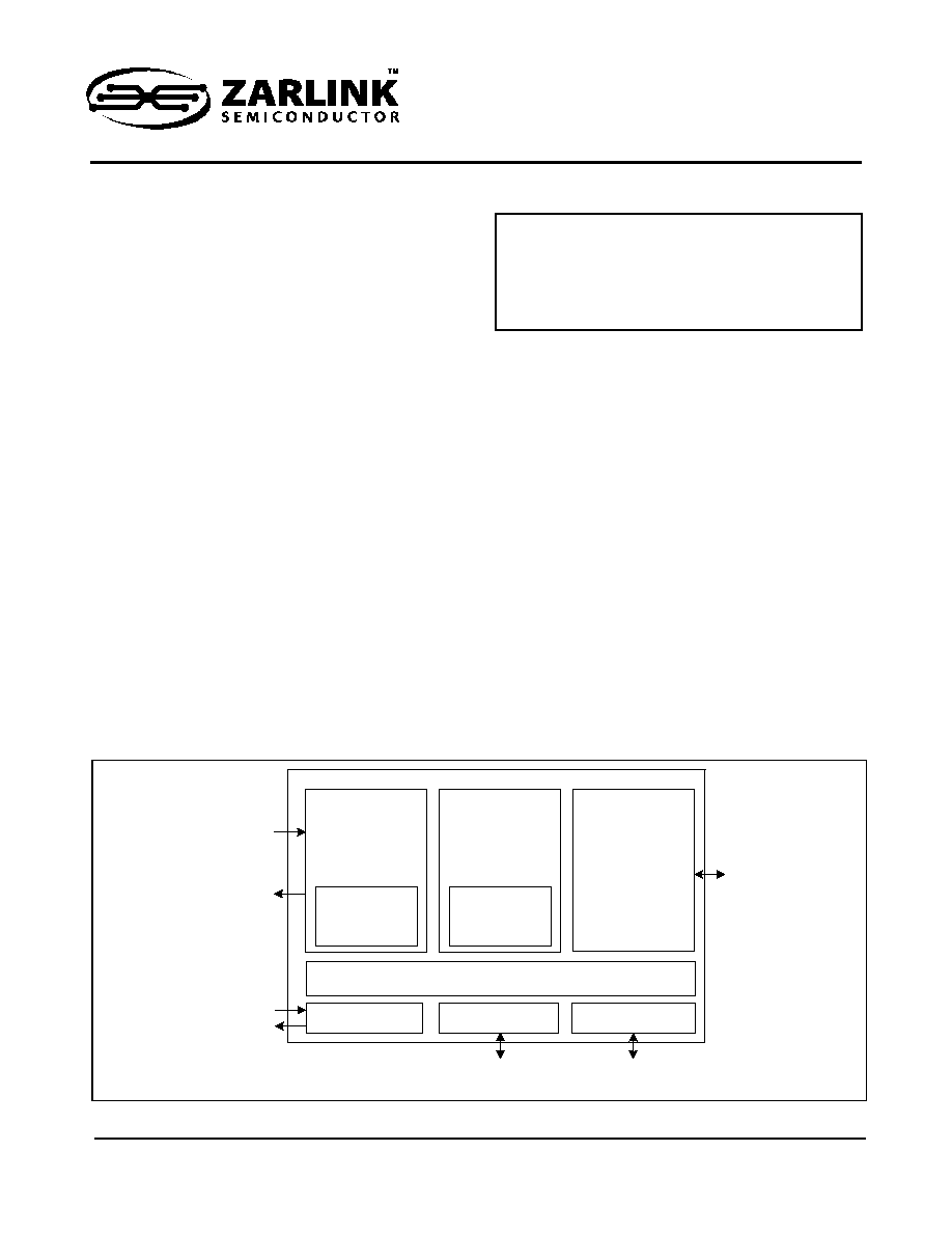
Figure 1 - ZL50110/11/14 High Level Overview
On Chip Packet Memory
(Jitter Buffer Compensation for 16-128 ms of Packet Delay Variation)
Dual Reference
Stratum 3 DPLL
Host Processor
Interface
External Memory
Interface (optional)
32 T
1
/
E
1,
8 J
2
,
2 T3/
E
3 or
1 S
T
S
-
1 por
t
s
H.
1
1
0
,
H-
M
V
I
P
,
S
T
-
B
US b
a
c
k
p
l
a
n
e
s
T
r
i
p
l
e
100
M
b
p
s
M
I
I
F
a
st
E
t
he
r
net
or
D
ual
R
e
d
udn
at
100
0 M
b
p
s
G
M
I
I
/
TB
I
G
i
g
abi
t
E
t
her
n
e
t
B
a
ckpl
ane
Cl
o
c
k
s
32-bit Motorola compatible
DMA for signaling packets
Multi-Protocol
Packet
Processing
Engine
PW, RTP, UDP,
IPv4, IPv6, MPLS,
ECID, VLAN, User
Defined, Others
Triple
Packet
Interface
MAC
(MII, GMII, TBI)
TDM
Interface
(LIU, Framer, Backplane)
Per Port DCO for
Clock Recovery
ZBT-SRAM
(0 - 8 Mbytes)

ZL50110/11/14
Data Sheet
2
Zarlink Semiconductor Inc.
Packet Processing Functions
� Flexible, multi-protocol packet encapsulation including IPv4, IPv6, RTP, MPLS, L2TPv3, ITU-T Y.1413., IETF
CESoPSN, IETF SAToP and user programmable
� Packet re-sequencing to allow lost packet detection
� Four classes of service with programmable priority mechanisms (WFQ and SP) using egress queues
� Flexible classification of incoming packets at layers 2, 3, 4, and 5
� Supports up to 128 separate CESoP connections across the Packet Switched Network
Applications
� Circuit Emulation Services over Packet Networks
� Leased Line support over packet networks
� Multi-Tenant Unit access concentration
� TDM over Cable
� Fibre To The Premises G/E-PON
� Layer 2 VPN services
� Customer-premise and Provider Edge Routers and Switches
� Packet switched backplane applications

ZL50110/11/14
Data Sheet
3
Zarlink Semiconductor Inc.
Description
The ZL50110/11/14 family of CESoP processors are highly functional TDM to Packet bridging devices. The
ZL50110/11/14 provides both structured and unstructured circuit emulation services over packet (CESoP) for up to
32 T1, 32 E1 and 8 J2 streams across a packet network based on MPLS, IP or Ethernet. The ZL50111 also
supports unstructured T3, E3 and STS-1 streams.
The circuit emulation features in the ZL50110/11/14 family comply with the ITU Recommendation Y.1413, as well as
the emerging CESoP standards from the Metro Ethernet Forum (MEF) and MPLS and Frame Relay Alliance (MFA).
The ZL50110/11/14 also complies with the standards currently being developed within the IETF's PWE3 working
group, listed below.
� Structure-Agnostic TDM over Packet (SAToP) - draft-ietf-pwe3-satop
� Structure-aware TDM Circuit Emulation Service over Packet Switched Network (CESoPSN) - draft-ietf-
pwe3-cesopsn
The ZL50110/11/14 provides up to triple 100 Mbps MII ports or dual redundant 1000 Mbps GMII/TBI ports.
The ZL50110/11/14 incorporates a range of powerful clock recovery mechanisms for each TDM stream, allowing
the frequency of the source clock to be faithfully generated at the destination, enabling greater system performance
and quality. Timing is carried using RTP or similar protocols, and both adaptive and differential clock recovery
schemes are included, allowing the customer to choose the correct scheme for the application. An externally
supplied clock may also be used to drive the TDM interface of the ZL50110/11/14.
The ZL50110/11/14 incur very low latency for the data flow, thereby increasing QoS when carrying voice services
across the Packet Switched Network. Voice, when carried using CESoP, which typically has latencies of less than
10 ms, does not require expensive processing such as compression and echo cancellation.
The ZL50110/11/14 is capable of assembling user-defined packets of TDM traffic from the TDM interface and
transmitting them out the packet interfaces using a variety of protocols. The ZL50110/11/14 supports a range of
different packet switched networks, including Ethernet VLANs, IP (both versions 4 and 6) and MPLS. The devices
also supports four different classes of service on packet egress, allowing priority treatment of TDM-based traffic.
This can be used to help minimize latency variation in the TDM data.
Packets received from the packet interfaces are parsed to determine the egress destination, and are appropriately
queued to the TDM interface, they can also be forwarded to the host interface, or back toward the packet interface.
Packets queued to the TDM interface can be re-ordered based on sequence number, and lost packets filled in to
maintain timing integrity.
The ZL50110/11/14 family includes sufficient on-chip memory that external memory is not required in most
applications. This reduces system costs and simplifies the design. For applications that do require more memory
(e.g., high stream count or high latency), the device supports up to 8 Mbytes of SSRAM.
A comprehensive evaluation system is available upon request from your local Zarlink representative or distributor.
This system includes the CESoP processor, various TDM interfaces and a fully featured evaluation software GUI
that will run on a Windows PC.

ZL50110/11/14
Data Sheet
4
Zarlink Semiconductor Inc.
Device Line Up
There are three products within the ZL50110/11/14 family, with capacity as shown in the following table:
Device
TDM Interfaces
Ethernet Packet I/F
ZL50114
4 T1, 4 E1, or 1 J2 streams or
4 MVIP/ST-BUS streams at 2.048 Mbps or
1 H.110/H-MVIP/ST-BUS streams at 8.192 Mbps
Dual 100 Mbps MII or
Dual Redundant 1000 Mbps GMII/TBI
ZL50110
8 T1, 8 E1 or 2 J2 streams or
8 MVIP/ST-BUS streams at 2.048 Mbps or
2 H.110/H-MVIP/ST-BUS streams at 8.192 Mbps
Dual 100 Mbps MII or
Dual Redundant 1000 Mbps GMII/TBI
ZL50111
32 T1, 32 E1, 8 J2, 2 T3, 2 E3 or 1 STS-1 streams or
32 MVIP/ST-BUS streams at 2.048 Mbps or
8 H.110/H-MVIP/ST-BUS streams at 8.192 Mbps
Triple 100 Mbps MII or
Dual Redundant 1000 Mbps GMII/TBI or
Single 100 Mbps MII and Single 1000
Mbps GMII/TBI
Table 1 - Capacity of Devices in the ZL50110/11/14 Family

ZL50110/11/14
Data Sheet
Table of Contents
5
Zarlink Semiconductor Inc.
1.0 Changes Summary . . . . . . . . . . . . . . . . . . . . . . . . . . . . . . . . . . . . . . . . . . . . . . . . . . . . . . . . . . . . . . . . . . . . 11
2.0 Physical Specification . . . . . . . . . . . . . . . . . . . . . . . . . . . . . . . . . . . . . . . . . . . . . . . . . . . . . . . . . . . . . . . . . . 12
3.0 External Interface Description . . . . . . . . . . . . . . . . . . . . . . . . . . . . . . . . . . . . . . . . . . . . . . . . . . . . . . . . . . . 21
3.1 TDM Interface . . . . . . . . . . . . . . . . . . . . . . . . . . . . . . . . . . . . . . . . . . . . . . . . . . . . . . . . . . . . . . . . . . . . . . 21
3.1.1 ZL50111 Variant TDM Stream Connection . . . . . . . . . . . . . . . . . . . . . . . . . . . . . . . . . . . . . . . . . . . 21
3.1.2 ZL50110 Variant TDM stream connection . . . . . . . . . . . . . . . . . . . . . . . . . . . . . . . . . . . . . . . . . . . . 24
3.1.3 ZL50114 Variant TDM Stream Connection . . . . . . . . . . . . . . . . . . . . . . . . . . . . . . . . . . . . . . . . . . . 25
3.1.4 TDM Signals Common to ZL50111, ZL50110 and ZL50114 . . . . . . . . . . . . . . . . . . . . . . . . . . . . . . 26
3.2 PAC Interface . . . . . . . . . . . . . . . . . . . . . . . . . . . . . . . . . . . . . . . . . . . . . . . . . . . . . . . . . . . . . . . . . . . . . . 27
3.3 Packet Interfaces. . . . . . . . . . . . . . . . . . . . . . . . . . . . . . . . . . . . . . . . . . . . . . . . . . . . . . . . . . . . . . . . . . . . 28
3.4 External Memory Interface . . . . . . . . . . . . . . . . . . . . . . . . . . . . . . . . . . . . . . . . . . . . . . . . . . . . . . . . . . . . 37
3.5 CPU Interface . . . . . . . . . . . . . . . . . . . . . . . . . . . . . . . . . . . . . . . . . . . . . . . . . . . . . . . . . . . . . . . . . . . . . . 39
3.6 System Function Interface. . . . . . . . . . . . . . . . . . . . . . . . . . . . . . . . . . . . . . . . . . . . . . . . . . . . . . . . . . . . . 41
3.7 Test Facilities. . . . . . . . . . . . . . . . . . . . . . . . . . . . . . . . . . . . . . . . . . . . . . . . . . . . . . . . . . . . . . . . . . . . . . . 42
3.7.1 Administration, Control and Test Interface. . . . . . . . . . . . . . . . . . . . . . . . . . . . . . . . . . . . . . . . . . . . 42
3.7.2 JTAG Interface . . . . . . . . . . . . . . . . . . . . . . . . . . . . . . . . . . . . . . . . . . . . . . . . . . . . . . . . . . . . . . . . . 42
3.8 Miscellaneous Inputs . . . . . . . . . . . . . . . . . . . . . . . . . . . . . . . . . . . . . . . . . . . . . . . . . . . . . . . . . . . . . . . . . 43
3.9 Power and Ground Connections . . . . . . . . . . . . . . . . . . . . . . . . . . . . . . . . . . . . . . . . . . . . . . . . . . . . . . . . 43
3.10 Internal Connections . . . . . . . . . . . . . . . . . . . . . . . . . . . . . . . . . . . . . . . . . . . . . . . . . . . . . . . . . . . . . . . . 44
4.0 Typical Applications . . . . . . . . . . . . . . . . . . . . . . . . . . . . . . . . . . . . . . . . . . . . . . . . . . . . . . . . . . . . . . . . . . . 44
4.1 Leased Line Provision . . . . . . . . . . . . . . . . . . . . . . . . . . . . . . . . . . . . . . . . . . . . . . . . . . . . . . . . . . . . . . . . 44
4.2 Metropolitan Area Network Aggregation . . . . . . . . . . . . . . . . . . . . . . . . . . . . . . . . . . . . . . . . . . . . . . . . . . 44
4.3 Digital Loop Carrier . . . . . . . . . . . . . . . . . . . . . . . . . . . . . . . . . . . . . . . . . . . . . . . . . . . . . . . . . . . . . . . . . . 45
4.4 Remote Concentrator . . . . . . . . . . . . . . . . . . . . . . . . . . . . . . . . . . . . . . . . . . . . . . . . . . . . . . . . . . . . . . . . 46
4.5 Cell Site Backhaul . . . . . . . . . . . . . . . . . . . . . . . . . . . . . . . . . . . . . . . . . . . . . . . . . . . . . . . . . . . . . . . . . . . 46
4.6 Metro Ethernet Equipment. . . . . . . . . . . . . . . . . . . . . . . . . . . . . . . . . . . . . . . . . . . . . . . . . . . . . . . . . . . . . 47
5.0 Functional Description . . . . . . . . . . . . . . . . . . . . . . . . . . . . . . . . . . . . . . . . . . . . . . . . . . . . . . . . . . . . . . . . . 48
5.1 Block Diagram . . . . . . . . . . . . . . . . . . . . . . . . . . . . . . . . . . . . . . . . . . . . . . . . . . . . . . . . . . . . . . . . . . . . . . 49
5.2 Data and Control Flows . . . . . . . . . . . . . . . . . . . . . . . . . . . . . . . . . . . . . . . . . . . . . . . . . . . . . . . . . . . . . . . 49
5.3 TDM Interface . . . . . . . . . . . . . . . . . . . . . . . . . . . . . . . . . . . . . . . . . . . . . . . . . . . . . . . . . . . . . . . . . . . . . . 50
5.3.1 TDM Interface Block. . . . . . . . . . . . . . . . . . . . . . . . . . . . . . . . . . . . . . . . . . . . . . . . . . . . . . . . . . . . . 50
5.3.2 Structured TDM Port Data Formats . . . . . . . . . . . . . . . . . . . . . . . . . . . . . . . . . . . . . . . . . . . . . . . . . 51
5.3.3 TDM Clock Structure . . . . . . . . . . . . . . . . . . . . . . . . . . . . . . . . . . . . . . . . . . . . . . . . . . . . . . . . . . . . 52
5.3.3.1 Synchronous TDM Clock Generation . . . . . . . . . . . . . . . . . . . . . . . . . . . . . . . . . . . . . . . . . . . 52
5.3.3.2 Asynchronous TDM Clock Generation . . . . . . . . . . . . . . . . . . . . . . . . . . . . . . . . . . . . . . . . . . 52
5.4 Payload Assembly . . . . . . . . . . . . . . . . . . . . . . . . . . . . . . . . . . . . . . . . . . . . . . . . . . . . . . . . . . . . . . . . . . . 52
5.4.1 Structured Payload Operation . . . . . . . . . . . . . . . . . . . . . . . . . . . . . . . . . . . . . . . . . . . . . . . . . . . . . 53
5.4.1.1 Structured Payload Order. . . . . . . . . . . . . . . . . . . . . . . . . . . . . . . . . . . . . . . . . . . . . . . . . . . . 54
5.4.2 Unstructured Payload Operation . . . . . . . . . . . . . . . . . . . . . . . . . . . . . . . . . . . . . . . . . . . . . . . . . . . 54
5.5 Protocol Engine . . . . . . . . . . . . . . . . . . . . . . . . . . . . . . . . . . . . . . . . . . . . . . . . . . . . . . . . . . . . . . . . . . . . . 55
5.6 Packet Transmission . . . . . . . . . . . . . . . . . . . . . . . . . . . . . . . . . . . . . . . . . . . . . . . . . . . . . . . . . . . . . . . . . 55
5.7 TDM Formatter . . . . . . . . . . . . . . . . . . . . . . . . . . . . . . . . . . . . . . . . . . . . . . . . . . . . . . . . . . . . . . . . . . . . . 55
6.0 Clock Recovery . . . . . . . . . . . . . . . . . . . . . . . . . . . . . . . . . . . . . . . . . . . . . . . . . . . . . . . . . . . . . . . . . . . . . . . 56
6.1 Differential Clock Recovery . . . . . . . . . . . . . . . . . . . . . . . . . . . . . . . . . . . . . . . . . . . . . . . . . . . . . . . . . . . . 56
6.2 Adaptive Clock Recovery . . . . . . . . . . . . . . . . . . . . . . . . . . . . . . . . . . . . . . . . . . . . . . . . . . . . . . . . . . . . . 57
6.3 SYSTEM_CLK Considerations . . . . . . . . . . . . . . . . . . . . . . . . . . . . . . . . . . . . . . . . . . . . . . . . . . . . . . . . . 57
7.0 System Features . . . . . . . . . . . . . . . . . . . . . . . . . . . . . . . . . . . . . . . . . . . . . . . . . . . . . . . . . . . . . . . . . . . . . . 58
7.1 Latency . . . . . . . . . . . . . . . . . . . . . . . . . . . . . . . . . . . . . . . . . . . . . . . . . . . . . . . . . . . . . . . . . . . . . . . . . . . 58
7.2 Loopback Modes . . . . . . . . . . . . . . . . . . . . . . . . . . . . . . . . . . . . . . . . . . . . . . . . . . . . . . . . . . . . . . . . . . . . 58
7.3 Host Packet Generation . . . . . . . . . . . . . . . . . . . . . . . . . . . . . . . . . . . . . . . . . . . . . . . . . . . . . . . . . . . . . . 58
7.4 Loss of Service (LOS) . . . . . . . . . . . . . . . . . . . . . . . . . . . . . . . . . . . . . . . . . . . . . . . . . . . . . . . . . . . . . . . . 59