Base off of CRO1940A. Lead free version.
Special bigger size.
Notes
CUSTOMER PRODUCT SPECIFICATION
Description
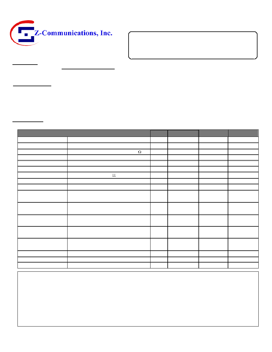
The following details the preliminary specification for a Voltage Controlled Oscillator centered at
MHz
The part number will be referred to as
.
CRO1877A-LF
Specifications
Unless otherwise stated, test conditions are at ambient operation conditions and under a 50 ohm load
Frequency Range
Parameter Test Condition Units Min. Typ. Max.
MHz
1835
1920
FR>=Fmin@VT(min)
0.5
FR<=Fmax@VT(max)
4.5
Pushing
Control Line Capacitance
MHz/V
MHz/V
MHz
dBc
dBc
dBm
pF
Output Power
Tuning Sensitivity (Kvco)
Harmonics
Non-Harmonics
Pulling
3
5
MHz < Fout <
1835
1920 MHz, 50
load
MHz < Fout <
1835
1920 MHz
MHz < Fout <
1835
1920 MHz
Vdc < Vtune <
Vdc
0.5
4.5
Vdc < Vcc <
Vdc
0 MHz < Fout < 3000 MHz
VSWR= :1, 0 to 2 (shorted line)
1.7
7
25
-15
5
5
50
1 kHz offset, all operating conditions,
1 Hz bandwidth
10 kHz offset, all operating conditions,
1 Hz bandwidth
kHz offset, all operating conditions,
1 Hz bandwidth
MHz offset, all operating conditions,
1 Hz bandwidth
kHz offset, all operating conditions,
1 Hz bandwidth
dBc/Hz
dBc/Hz
dBc/Hz
dBc/Hz
dBc/Hz
Vdc
mA
∞C
-87
-112
Phase Noise
Phase Noise
Phase Noise
Phase Noise
Phase Noise
Supply Voltage
Supply Current
Operating Temperature
All operating conditions
Ambient Case Temperature
-40
+85
25
5
4.75
5
Vcc=
Vdc
5.25
4.7
5.3
Application Notes
1.
2.
3.
Please refer to application notes AN-101, AN-102 and AN-107 for additional information on proper layout,
grounding and soldering of Z-COMM VCOs.
A
Revision Level
2523
CPS Number
CRO1877A-LF
Z-COMM Part Number
Page 1/2
0.546" x 0.866
1835 1920
0.5 4.5
VCO, FR=
MHz, Vt=
-
-
Vdc
-90
9939 Via Pasar ∑ San Diego, CA 92126 ∑ TEL: 858-621-2700 ∑ FAX: 858-621-2722 ∑ Internet: www.zcomm.com ISO FRM-S-001
Tuning Voltage
Vdc
All operating conditions
with 85
MHz nominal tuning range.
1877.5
F
R & K
Customer SCD
Contact
Customer
Customer Approval
Daito Electron Co., LTD.
Masahito Kimura
Packaging
This device shall be available in tape/reel or bulk packaging: please consult factory for minimum order and
other details on mechanical dimensions for reels.
Z-COMM Eng. Review
Ajay Saini
Originator
November 1, 2005
Date of Origin
1/9/2006
Last Revised
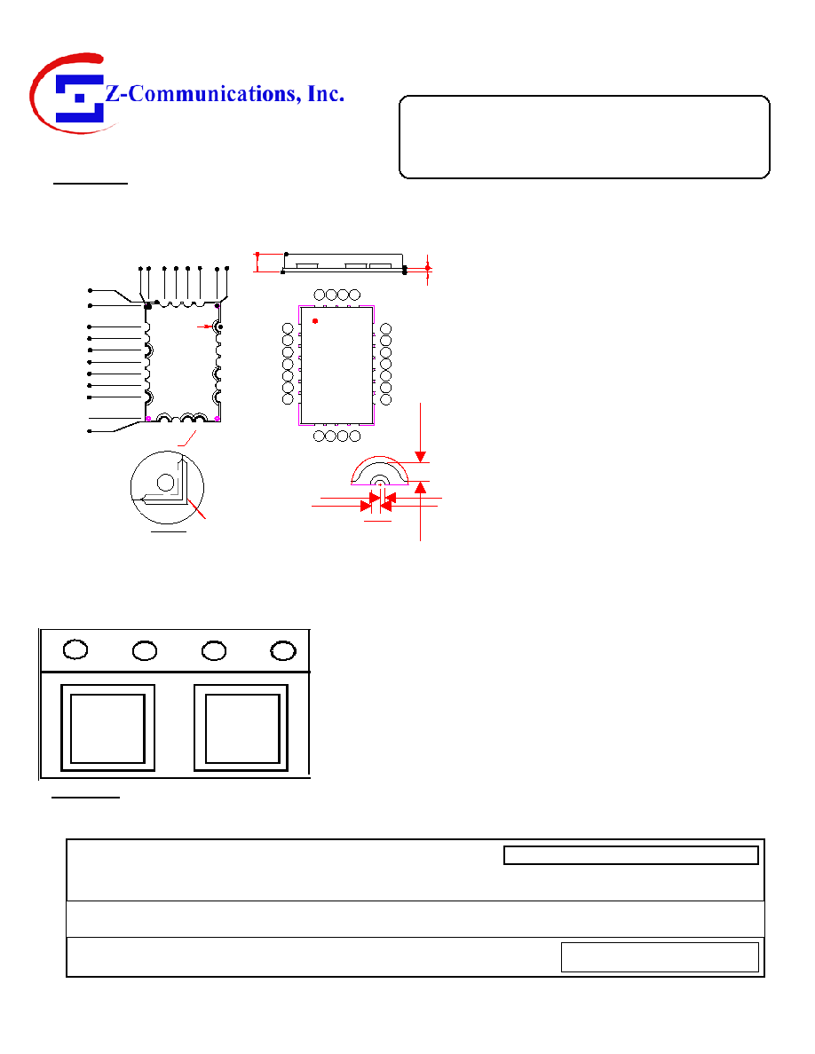
Mechanical
0.546" x 0.866
Package Style:
16
18
14
12
1
2
3
4
8
10 11
22
20 19
5
6
7
9
13
15
17
21
TOP
TABS RANGE:
SEE NOTE 5
(4 PLACES)
DETAIL A
.015
.030
.055
DETAIL B (TYP)
(8 PLACES)
1.
The inside radius of all 24 half holes at the perimeter of
the board are plated to provide a surface for the
attachment of the PLL Module to the PCB. 16 pads are
for grounding, 8 pads are for signal interface.
2.
The surface of the shield is tin-plated and may be
soldered to. The shield's base metal is cold-rolled steel.
3.
The ground plane on the bottom side is ground and
attaches to a ground track on the top side of the board
as well as to the shield.
4.
Unless otherwise noted all dimensions are in inches.
5.
Unless otherwise noted all tolerances are as follows:
.xxx =
± .010.
SEE DETAIL A
SEE DETAIL B
0.22
0
.03
2
SIDE VIEW
-.0
2
6
PIN 1
BOTTOM
.000
.153
.238
.323
.408
.493
.578
.663
-.025
.841
.
000
.
115
.
200
.
285
.
370
.
495
.
520
.816
Orientation, Marking & Placement of the VCO into Tape
Z-COMM
CRO1877A
-LF
WO#
A
Revision Level
2523
CPS Number
CRO1877A-LF
Z-COMM Part Number
Page 2/2
0.546" x
1835 1920
0.5 4.5
VCO, FR=
MHz, Vt=
-
-
Vdc
9939 Via Pasar ∑ San Diego, CA 92126 ∑ TEL: 858-621-2700 ∑ FAX: 858-621-2722 ∑ Internet: www.zcomm.com ISO FRM-S-001
CUSTOMER PRODUCT SPECIFICATION
Z-COMM
CRO1877A
-LF
WO#
Package Footprint