ISSUE 3 - APRIL 2001
ZDC834A
1
1
2
3
PIN CONFIGURATION
SILICON DUAL VARIABLE CAPACITANCE DIODE
C1
C2
A1
A2
SUMMARY
V
BR
=25V; I
R
=20nA; C
d
=47pF(Nom)
DESCRIPTION
The ZDC834A is a new hyperabrupt SOT23 packaged dual common cathode
varactor diode , offering users both compact circuit design and impressive
performance comprising tightly controlled CV characteristics, a capacitance
of typically 47 pf @ 2V,excellent phase noise performance and high Q of 200
min.
This superior performance in the VHF and UHF ranges has been optimised to
meet the high filtering requirements of a wide range of Digital Audio
Broadcasting
(DAB) module circuits , mobile radios, pagers, voltage
controlled crystal oscillators (VCXO) and temperature controlled crystal
oscillators (TCXO).
FEATURES
∑
Common Cathode dual Diode ( monolithic construction )
∑
VHF- UHF operation
∑
Close tolerance CV characteristics
∑
High Tuning Ratio
∑
Low I
R
, enabling excellent Phase Noise Performance
( I
R
typically < 200pA @ 20V )
∑
High Q
APPLICATIONS
∑
DAB Receiver Modules for use with:
- Low voltage battery portables
- Hi-Fi
- In car radio
- MP3 players
∑
Voltage and Temperature Controlled Crystal Oscillators
∑
Mobile Radio and Pagers.
ORDERING INFORMATION
DEVICE
REEL SIZE
(inches)
TAPE WIDTH (mm)
QUANTITY
PER REEL
ZDC834ATA
7
8mm embossed
3000 units
DEVICE MARKING
∑
C5A
Top View
SOT23
ISSUE 3 - APRIL 2001
ZDC834A
2
ABSOLUTE MAXIMUM RATINGS.
PARAMETER
SYMBOL
VALUE
UNIT
Forward Current (single diode)
I
F
200
mA
Power Dissipation at T
amb
=25∞C (a)
Linear Derating Factor
P
D
330
3
mW
mW/∞C
Operating and Storage Temperature Range
T
j
:T
stg
-55 to +150
∞C
THERMAL RESISTANCE
PARAMETER
SYMBOL
VALUE
UNIT
Junction to Ambient (a)
R
JA
417
∞C/W
NOTES
(a) For a device surface mounted on 25mm x 25mm FR4 PCB with high coverage of single sided 1oz copper,
in still air conditions
ELECTRICAL CHARACTERISTICS (at T
amb
= 25∞C ).
PARAMETER
SYMBOL
MIN.
TYP.
MAX.
UNIT
CONDITIONS.
Reverse Breakdown
Voltage
V
BR
25
V
I
R
= 10
µ
A
Reverse Leakage Current
I
R
0.2
20
nA
V
R
= 20V
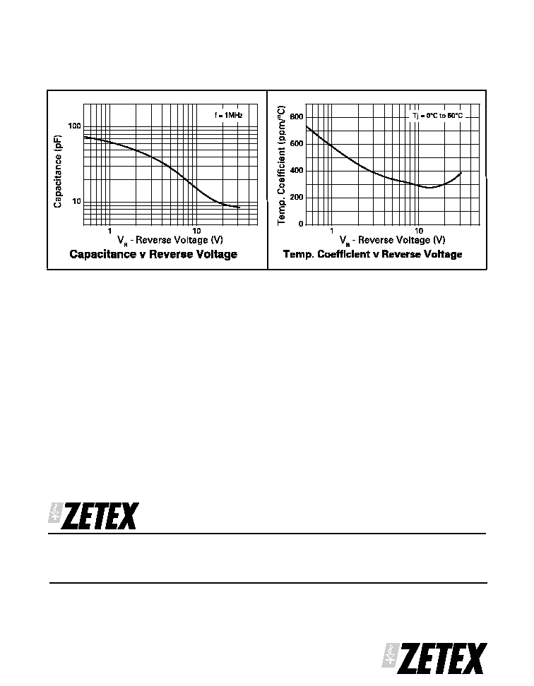
Temperature Coefficient
400
ppm/∞C
V
R
= 3V, f=1MHz
Diode Capacitance
C
d
42.3
47
51.7
pF
V
R
= 2V, f=1MHz
Capacitance Ratio
C
d
/ C
d
5.0
6.5
V
R
= 2V/20V, f=1MHz
Figure of Merit
Q
200
V
R
= 3V, f=50MHz

ISSUE 3 - APRIL 2001
ZDC834A
3
APPLICATIONS INFORMATION
ZDC834A in Digital Audio
Broadcasting (DAB) Circuits
Digital audio is set to dominate car radio and other
mobile radio applications. Most of the required
functions can be achieved with a single integrated
circuit. One part of the circuit that is not integrated is
the Voltage Controlled Oscillator (VCO) used in the
Phase-Locked Loop (PLL) channel selection circuit.
F i g u r e 1 s h o w s t h e Z D C 8 3 4 A d u a l v a r i a b l e
capacitance diode (also known as varactor or tuner
diode) in a DAB application.
Most textbook circuits show a single variable
capacitance diode in place of the ZDC834A. In practice
radio frequency oscillations in the tank circuit can
drive the single diode into conduction on peaks
increasing the bias voltage and giving rise to
undesirable harmonics. Common-cathode variable
capacitance diodes are used to overcome this
problem. The ZDC834A dual common cathode device
in the space saving SOT23 package has been
optimized for this application. Zetex application note
AN9 covers our range of variable capacitance diodes
and their applications in detail.
ZDC834A
ZDC834A
ZDC834A
DAB Chipset
control voltage
control voltage
control voltage
Figure 1
ISSUE 3 - APRIL 2001
ZDC834A
4
CHARACTERISTICS
Additional CV matching capability:
Zetex recognise that some applications ie filtering in digital audio receiver circuits, require these dual varactors
to be very tightly matched. To meet this requirement devices can be supplied tested into capacitance bands at the
2V condition.
Each ( TA ) reel will contain 3000 devices carrying only diodes tested into a single band and each device will have
a partmark identifying the capacitance band which they meet.
Cd specification at 2V, 1MHz
Band A = 42.3pf to 45.5pf partmark is 71A
Band B = 45.4pf to 48.6pf partmark is 71B
Band C = 48.5pf to 51.7pf partmark is 71C
As this is a final test measurement customers will not have the option to specify a capacitance at the time of
ordering and will be obliged to accept the band into which the devices are tested.
Should this be of interest the specification identification would change from ZDC834A to FSD271 and
- Purchase orders can be placed in multiples of 3000 units / reel for device type FSD271TA
- Samples can be obtained from Zetex Plc quoting device type #FSD271TA
Zetex plc.
Fields New Road, Chadderton, Oldham, OL9-8NP, United Kingdom.
Telephone: (44)161 622 4422 (Sales), (44)161 622 4444 (General Enquiries)
Fax: (44)161 622 4420
Zetex GmbH
Zetex Inc.
Zetex (Asia) Ltd.
These are supported by
Streitfeldstraþe 19
47 Mall Drive, Unit 4
3701-04 Metroplaza, Tower 1
agents and distributors in
D-81673 M¸nchen
Commack NY 11725
Hing Fong Road,
major countries world-wide
Germany
USA
Kwai Fong, Hong Kong
© Zetex plc 2001
Telefon: (49) 89 45 49 49 0
Telephone: (631) 543-7100
Telephone:(852) 26100 611
Fax: (49) 89 45 49 49 49
Fax: (631) 864-7630
Fax: (852) 24250 494
www.zetex.com
This publication is issued to provide outline information only which (unless agreed by the Company in writing) may not be used, applied or reproduced for
any purpose or form part of any order or contract or be regarded as a representation relating to the products or services concerned. The Company reserves
the right to alter without notice the specification, design, price or conditions of supply of any product or service.