 | –≠–ª–µ–∫—Ç—Ä–æ–Ω–Ω—ã–π –∫–æ–º–ø–æ–Ω–µ–Ω—Ç: ZRA125 | –°–∫–∞—á–∞—Ç—å:  PDF PDF  ZIP ZIP |
S E M I C O N D U C T O R S
DESCRIPTION
The ZRA125 uses a bandgap circuit design to achieve a
precision micropower voltage reference of 1.25 volts.
The device is available in small outline surface mount
packages, ideal for applications where space saving is
important.
The ZRA125 design provides a stable voltage without
an external capacitor and is stable with capacitive
loads. The ZRA125 is recommended for operation
between 50 A and 5mA and so is ideally suited to low
power and battery powered applications.
Excellent performance is maintained to a suggested
absolute maximum of 25mA, however the rugged
design and 20 volt processing allows the reference to
withstand transient effects and currents up to 200mA.
Superior switching capability allows the device to
reach stable operating conditions in only a few
microseconds.
FEATURES
∑
No stabilizing capacitor required
∑
Typical T
C
30ppm/∞C
∑
Typical slope resistance 0.65
∑
± 3% and 2% tolerance
∑
Industrial temperature range
∑
Operating current 50 A to 5mA
∑
Transient response, stable in less than 10 s
∑
Small outline SOT23 package
APPLICATIONS
∑
Battery powered and portable equipment
∑
Metering and measurement systems
∑
Instrumentation
∑
Data acquisition systems
∑
Precision power supplies
∑
Test equipment
ZRA125
ISSUE 3 - MARCH 2004
PRECISION 1.25 VOLT MICROPOWER VOLTAGE REFERENCE
1
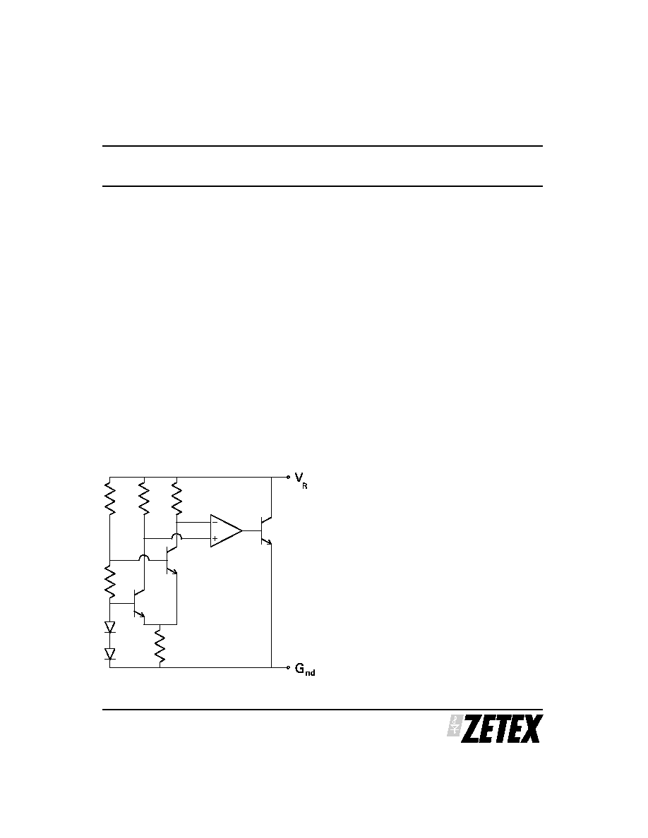
SCHEMATIC DIAGRAM
NOTES:
(1)
T
V change x
V
X temperature change
C
R
R
=
1000 000
,
,
TC is a characterized parameter not measured on
individual devices.
(2)
R
V change I
to
to I
I
I
S
R
R
R
R
R
=
-
( (min)
(min)
(max))
(max)
(min)
ZRA125
S E M I C O N D U C T O R S
ISSUE 3 - MARCH 2004
2
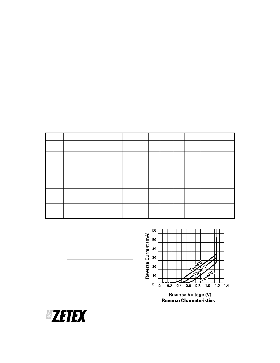
Reverse current
25mA
Forward current
25mA
Operating temperature
-40 to 85∞C
Storage temperature
-55 to 150∞C
POWER DISSAPATION (T
amb
= 25∞C)
SOT23
330mW
ABSOLUTE MAXIMUM RATINGS
SYMBOL PARAMETER
CONDITIONS MIN.
TYP.
MAX.
TOL %
UNITS
V
R
Reverse breakdown voltage
I
R
= 150 A
1.225
1.21
1.25
1.25
1.275
1.29
2
3
V
V
I
MIN
Minimum operating current
30
50
A
I
R
Recommended operating
current
0.05
5
mA
T
C
(1)
Average reverse breakdown
voltage temp. co.
I
R
(min) to
I
R
(max)
30
90
ppm/∞C
R
S
(2)
Slope resistance
0.65
2
Z
R
Reverse dynamic impedance
I
R
= 1mA
f = 100Hz
I
AC
= 0.1I
R
0.5
1
E
N
Wideband Noise Voltage
I
R
= 150 A
f = 100Hz to
10kHZ
40
V(rms)
ELECTRICAL CHARACTERISTICS (at T
amb
= 25∞C unless otherwise stated)
ZRA125
S E M I C O N D U C T O R S
ISSUE 3 - MARCH 2004
3
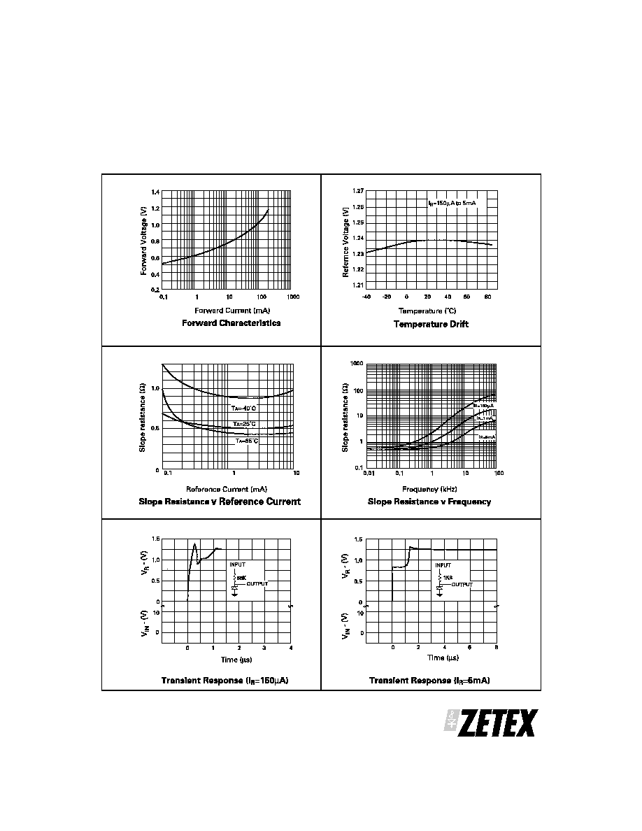
TYPICAL CHARACTERISTICS
ZRA125
S E M I C O N D U C T O R S
ISSUE 3 - MARCH 2004
4
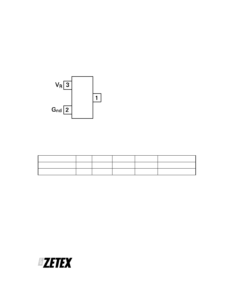
CONNECTION DIAGRAM
Package Suffix - F
TOP VIEW
Pin 1 floating or connected to pin 2
Part Number
Tol %
Package
Part Mark
Reel Size
Quantity per reel
ZRA125F02TA
2
SOT23
12B
7"
3,000
ZRA125F03TA
3
SOT23
12A
7"
3,000
ORDERING INFORMATION

ZRA125
S E M I C O N D U C T O R S
ISSUE 3 - MARCH 2004
5
Europe
Zetex GmbH
Streitfeldstraþe 19
D-81673 M¸nchen
Germany
Telefon: (49) 89 45 49 49 0
Fax: (49) 89 45 49 49 49
europe.sales@zetex.com
Americas
Zetex Inc
700 Veterans Memorial Hwy
Hauppauge, NY 11788
USA
Telephone: (1) 631 360 2222
Fax: (1) 631 360 8222
usa.sales@zetex.com
Asia Pacific
Zetex (Asia) Ltd
3701-04 Metroplaza Tower 1
Hing Fong Road, Kwai Fong
Hong Kong
Telephone: (852) 26100 611
Fax: (852) 24250 494
asia.sales@zetex.com
Corporate Headquaters
Zetex plc
Fields New Road, Chadderton
Oldham, OL9 8NP
United Kingdom
Telephone (44) 161 622 4444
Fax: (44) 161 622 4446
hq@zetex.com
These offices are supported by agents and distributors in major countries world-wide.
This publication is issued to provide outline information only which (unless agreed by the Company in writing) may not be used, applied or reproduced
for any purpose or form part of any order or contract or be regarded as a representation relating to the products or services concerned. The Company
reserves the right to alter without notice the specification, design, price or conditions of supply of any product or service.
For the latest product information, log on to www.zetex.com
© Zetex plc 2004
Controlling dimensions are in millimeters. Approximate conversions are given in inches
PACKAGE OUTLINE
PAD LAYOUT DETAILS
DIM
Millimeters
Inches
DIM
Millimeters
Inches
Min
Max
Min
Max
Min
Max
Max
Max
A
2.67
3.05
0.105
0.120
H
0.33
0.51
0.013
0.020
B
1.20
1.40
0.047
0.055
K
0.01
0.10
0.0004
0.004
C
1.10
0.043
L
2.10
2.50
0.083
0.0985
D
0.37
0.53
0.015
0.021
M
0.45
0.64
0.018
0.025
F
0.085
0.15
0.0034
0.0059
N
0.95 NOM
0.0375 NOM
G
1.90 NOM
0.075 NOM
PACKAGE DIMENSIONS