 | –≠–ª–µ–∫—Ç—Ä–æ–Ω–Ω—ã–π –∫–æ–º–ø–æ–Ω–µ–Ω—Ç: ZSR570C | –°–∫–∞—á–∞—Ç—å:  PDF PDF  ZIP ZIP |

DEVICE DESCRIPTION
The ZSR Series three terminal fixed positive voltage
regulators feature internal circuit current limit and
thermal shutdown making the devices difficult to
destroy. The circuit design allows creation of any
custom voltage in the range 2.85 to 12 volts. The
devices are available in a small outline surface mount
package, ideal for applications where space saving is
important, as well as through hole TO92 style
packaging. The devices are suited to local voltage
regulation applications, where problems could be
encountered with distributed single source regulation,
a s w e l l a s m o r e g e n e r a l v o l t a g e r e g u l a t i o n
applications.
The ZSR Series show performance characteristics
superior to other local voltage regulators. The initial
output voltage is maintained to within 2.5% with a
quiescent current of typically 350
µ
A. Output voltage
change, with input voltage and load current, is much
lower than competitive devices. The ZSR devices are
completely stable with no external components.
FEATURES
∑
Small outline SO8 and SOT223 package
∑
TO92 package
∑
2.85 to 12 Volt
∑
Output current up to 200mA
∑
Tight initial tolerance
∑
Low quiescent current
∑
-55 to 125∞C temperature range
∑
No external components
∑
Internal thermal shutdown
∑
Internal short circuit current limit
VOLTAGE RANGE
ZSR285
2.85V
ZSR300
3.0V
ZSR330
3.3V
ZSR400
4.0V
ZSR485
4.85V
ZSR500
5.0V
ZSR520
5.2V
ZSR570
5.7V
ZSR600
6.0V
ZSR700
7.0V
ZSR800
8.0V
ZSR850
8.5V
ZSR900
9.0V
ZSR1000
10.0V
ZSR1200
12.0V
ISSUE 3 - SEPTEMBER 2001
ZSR
SERIES
2.85 TO 12 VOLT FIXED POSITIVE
LOCAL VOLTAGE REGULATOR
1

ZSR
SERIES
ABSOLUTE MAXIMUM RATING
Input voltage
20V
Output Current(I
o
)
200mA
Operating Temperature
-55 to 125∞C
Storage Temperature
-65 to 150∞C
ELECTRICAL CHARACTERISTICS
Notes:
1. The maximum operating input voltage and output
current of the device will be governed by the
maximum power dissipation of the selected package.
Maximum package power dissipation is specified at
25 ∞C and must be linearly derated to zero at
T
amb
=125∞C.
2. The following data represents pulse test conditions
with junction temperatures as indicated at the
initiation of the test. Continuous operation of the
devices with the stated conditions might exceed the
power dissipation limits of the chosen package.
Power Dissipation (T
amb
=25∞C)
SOT223
2W(Note 3)
TO92
600mW
S08
780mW(Note 3)
3. Maximum power dissipation, for the SOT223 and
SO8 packages, is calculated assuming that the device
is mounted on a PCB measuring 2 inches square.
4. The shut down feature of the device operates if its
temperature exceeds its design limit as might occur
during external faults, short circuits etc. If the
regulator is supplied from an inductive source then a
large voltage transient, on the regulator input, can
result should the shut down circuit operate. It is
advised that a capacitor (1
µ
F or greater) should be
applied across the regulator input to ensure that the
maximum voltage rating of the device is not
exceeded under shutdown conditions.
ISSUE 3 - SEPTEMBER 2001
2
SYMBOL
PARAMETER
CONDITIONS
MIN.
TYP.
MAX.
UNITS
V
O
Output Voltage
2.78
2.85
2.92
V
I
O
=1 to 200mA
2.736
2.964
V
V
in
=4.85 to 20V
I
O
=1 to 100mA
2.736
2.964
V
V
O
Line Regulation
V
in
=4.85 to 20V
10
40
mV
V
O
Load Regulation
I
O
=1 to 200mA
I
O
=1 to 100mA
5
2
25
mV
mV
l
q
Quiescent Current
350
600
µ
A
l
q
Quiescent Current
Change
I
O
=1 to 200mA
V
in
=4.85 to 20V
100
100
µ
A
µ
A
V
n
Output Noise Voltage
f=10Hz to 10kHz
75
µ
V rms
V
in
/
V
O
Ripple Rejection
V
in
=5.85 to 18V
f=120Hz
48
62
dB
V
in
Input Voltage Required
To Maintain Regulation
4.85
4.55
V
V
O
/
T
Average Temperature
Coefficient of V
O
I
O
=5.0mA
0.1
mV/∞C
ZSR285 TEST CONDITIONS (Unless otherwise stated):T
j
=25∞C, I
O
=100mA, V
in
=6.85V
=T
j
=-55 to 125∞C
ISSUE 3 - SEPTEMBER 2001
3
ZSR
SERIES
SYMBOL
PARAMETER
CONDITIONS
MIN.
TYP.
MAX.
UNITS
V
O
Output Voltage
3.218
3.3
3.382
V
I
O
=1 to 200mA
3.168
3.432
V
V
in
=5.3 to 20V
I
O
=1 to 100mA
3.168
3.432
V
V
O
Line Regulation
V
in
=5.3 to 20V
7.5
30
mV
V
O
Load Regulation
I
O
=1 to 200mA
I
O
=1 to 100mA
5
2
25
mV
mV
l
q
Quiescent Current
350
600
µ
A
l
q
Quiescent Current Change I
O
=1 to 200mA
V
in
=5.3 to 20V
100
100
µ
A
µ
A
V
n
Output Noise Voltage
f=10Hz to 10kHz
50
µ
V rms
V
in
/
V
O
Ripple Rejection
V
in
=6.3 to 18V
f=120Hz
50
64
dB
V
in
Input Voltage Required To
Maintain Regulation
5.3
5
V
V
O
/
T
Average Temperature
Coefficient of V
O
I
O
=5.0mA
0.1
mV/∞C
ZSR330 TEST CONDITIONS (Unless otherwise stated):T
j
=25∞C, I
O
=100mA, V
in
=7.3V
=T
j
=-55 to 125∞C
SYMBOL
PARAMETER
CONDITIONS
MIN.
TYP.
MAX.
UNITS
V
O
Output Voltage
2.92
3.0
3.08
V
I
O
=1 to 200mA
2.88
3.12
V
V
in
=5 to 20V
I
O
=1 to 100mA
2.88
3.12
V
V
O
Line Regulation
V
in
=5 to 20V
10
40
mV
V
O
Load Regulation
I
O
=1 to 200mA
I
O
=1 to 100mA
5
2
25
mV
mV
l
q
Quiescent Current
350
600
µ
A
l
q
Quiescent Current Change I
O
=1 to 200mA
V
in
=5 to 20V
100
100
µ
A
µ
A
V
n
Output Noise Voltage
f=10Hz to 10kHz
75
µ
V rms
V
in
/
V
O
Ripple Rejection
V
in
=6 to 18V
f=120Hz
48
62
dB
V
in
Input Voltage Required To
Maintain Regulation
5
4.7
V
V
O
/
T
Average Temperature
Coefficient of V
O
I
O
=5.0mA
0.1
mV/∞C
ZSR300 TEST CONDITIONS (Unless otherwise stated):T
j
=25∞C, I
O
=100mA, V
in
=7V

ZSR
SERIES
ISSUE 3 - SEPTEMBER 2001
4
SYMBOL
PARAMETER
CONDITIONS
MIN.
TYP.
MAX.
UNITS
V
O
Output Voltage
3.9
4.0
4.1
V
I
O
=1 to 200mA
3.84
4.16
V
V
in
=6 to 20V
I
O
=1 to 100mA
3.84
4.16
V
V
O
Line Regulation
V
in
=6 to 20V
10
40
mV
V
O
Load Regulation
I
O
=1 to 200mA
I
O
=1 to 100mA
5
2
25
mV
mV
l
q
Quiescent Current
350
600
µ
A
l
q
Quiescent Current
Change
I
O
=1 to 200mA
V
in
=6 to 20V
100
100
µ
A
µ
A
V
n
Output Noise Voltage
f=10Hz to 10kHz
75
µ
V rms
V
in
/
V
O
Ripple Rejection
V
in
=7 to 18V
f=120Hz
48
62
dB
V
in
Input Voltage Required
To Maintain Regulation
6
5.3
V
ZSR400 TEST CONDITIONS (Unless otherwise stated):T
j
=25∞C, I
O
=100mA, V
in
=8V
SYMBOL
PARAMETER
CONDITIONS
MIN.
TYP.
MAX.
UNITS
V
O
Output Voltage
4.729
4.85
4.971
V
I
O
=1 to 200mA
4.656
5.044
V
V
in
=6.8 to 20V
I
O
=1 to 100mA
4.656
5.044
V
V
O
Line Regulation
V
in
=6.85 to 20V
10
40
mV
V
O
Load Regulation
I
O
=1 to 200mA
I
O
=1 to 100mA
5
2
25
mV
mV
l
q
Quiescent Current
350
600
µ
A
l
q
Quiescent Current
Change
I
O
=1 to 200mA
V
in
=6.85 to 20V
100
100
µ
A
µ
A
V
n
Output Noise Voltage
f=10Hz to 10kHz
50
µ
V rms
V
in
/
V
O
Ripple Rejection
V
in
=7.85 to 18V
f=120Hz
50
64
dB
V
in
Input Voltage Required
To Maintain Regulation
6.85
6.55
V
V
O
/
T
Average Temperature
Coefficient of V
O
I
O
=5.0mA
0.1
mV/∞C
=T
j
= -55 to 125∞C
ZSR485 TEST CONDITIONS (Unless otherwise stated): T
j
=25∞C, I
O
=100mA, V
in
=8.85V

ISSUE 3 - SEPTEMBER 2001
5
ZSR
SERIES
SYMBOL
PARAMETER
CONDITIONS
MIN.
TYP.
MAX.
UNITS
V
O
Output Voltage
11.7
12
12.3
V
I
O
=1 to 200mA
11.52
12.48
V
V
in
=14 to 20V
I
O
=1 to 100mA
11.52
12.48
V
V
O
Line Regulation
V
in
=14 to 20V
12
40
mV
V
O
Load Regulation
I
O
=1 to 200mA
I
O
=1 to 100mA
9
3
30
mV
mV
l
q
Quiescent Current
350
600
µ
A
l
q
Quiescent Current Change
I
O
=1 to 200mA
V
in
=14 to 20V
100
100
µ
A
µ
A
V
n
Output Noise Voltage
f=10Hz to 10kHz
150
µ
V rms
V
in
/
V
O
Ripple Rejection
V
in
=15 to 18V
f=120Hz
43
57
dB
V
in
Input Voltage Required To
Maintain Regulation
14
13.7
V
V
O
/
T
Average Temperature
Coefficient of V
O
I
O
=5.0mA
0.25
mV/∞C
ZSR1200 TEST CONDITIONS (Unless otherwise stated): T
j
=25∞C, I
O
=100mA, V
in
=16V
=T
j
= -55 to 125 ∞C
SYMBOL
PARAMETER
CONDITIONS
MIN.
TYP.
MAX.
UNITS
V
O
Output Voltage
9.75
10
10.25
V
I
O
=1 to 200mA
9.6
10.4
V
V
in
=12 to 20V
I
O
=1 to 100mA
9.6
10.4
V
V
O
Line Regulation
V
in
=12 to 20V
12
40
mV
V
O
Load Regulation
I
O
=1 to 200mA
I
O
=1 to 100mA
9
3
30
mV
mV
l
q
Quiescent Current
350
600
µ
A
l
q
Quiescent Current Change
I
O
=1 to 200mA
V
in
=12 to 20V
100
100
µ
A
µ
A
V
n
Output Noise Voltage
f=10Hz to 10kHz
150
µ
V rms
V
in
/
V
O
Ripple Rejection
V
in
=13 to 18V
f=120Hz
43
57
dB
V
in
Input Voltage Required To
Maintain Regulation
12
11.7
V
V
O
/
T
Average Temperature
Coefficient of V
O
I
O
=5.0mA
0.25
mV/∞C
ZSR1000 TEST CONDITIONS (Unless otherwise stated): T
j
=25∞C, I
O
=100mA, V
in
=14V

ZSR
SERIES
ZSR285 ZSR300 ZSR400
ZSR570 ZSR900
ISSUE 3 - SEPTEMBER 2001
6
Th
erm
a
l
Res
ista
nce
(
∞
C
/
W
)
1m
10m 100m
10
1
0
8
16
24
32
40
48
D=0
D=0.05
D=0.1
D=0.2
D=0.5
D=1
Pulse Width(s)
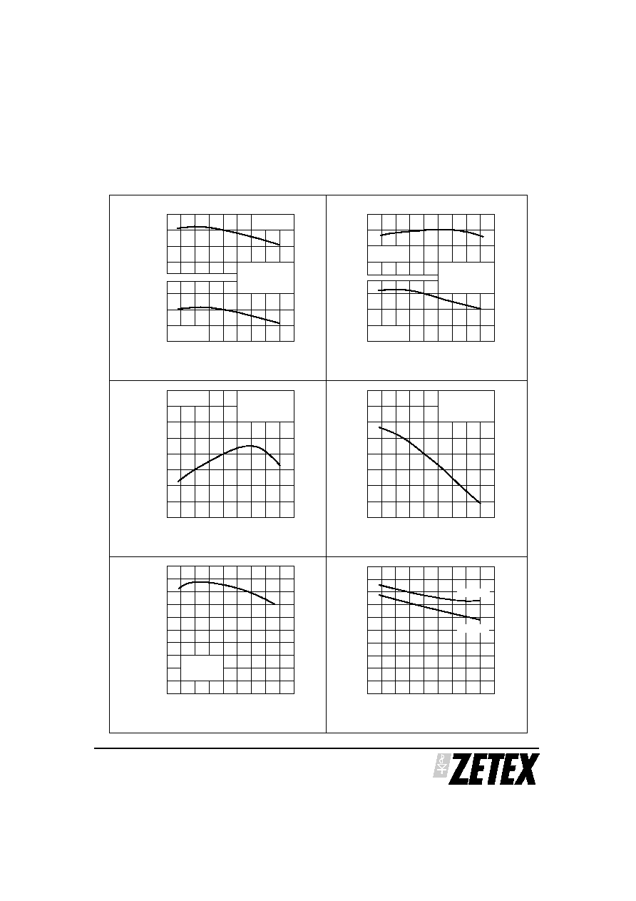
Thermal Resistance v Pulse Width
Thermal Resistance v Pulse Width
Th
erm
a
l
Resi
s
tan
c
e
(
∞
C
/
W
)
SOT223 PACKAGE
0
10
20
30
40
50
-1.0
-0.5
0
+0.5
OUTPUT VOLTAGE
DEVIATION
Time (us)
Line Transient Response
INPUT VOLTAGE
I
O
= 100mA
C
OUT
= 0
dV
IN
/dt = 5V/
µ
s
(V + 9)
(V + 4)
O
O
0
10
20
30
40
50
-1.0
-0.5
0
+0.5
0
OUTPUT VOLTAGE
DEVIATION
LOAD CURRENT
Time (us)
O
u
t
p
u
t
V
o
l
t
ag
e
Deviat
io
n
(
V)
Load Transient Response
V
IN
= V
o
+ 4V
C
OUT
= 0
dI
o
/dt = 1A/
µ
s
100 mA
0
10
20
30
40
50
60
70
80
90
10
100
1K
10K
100K
Ripple Frequency (Hz)
Ri
pp
le
Rej
ect
io
n
(
d
B
)
I
o
= 100mA
V
in
= V
out
+ 3V
DV
in
= 200mV p/p
ZSR285
ZSR400
ZSR570
ZSR900
100
1K
10K
100K
10
1.0
0.1
0.01
ZSR900
ZSR570
ZSR400
ZSR285
Frequency (Hz)
O
u
t
p
u
t
Im
ped
anc
e
(
O
h
m
s
)
I
o
= 100mA
V
IN
= V
OUT
+ 4V
Output Impedance v Frequency
Ripple Rejection v Ripple Frequency
ZSR300
ZSR300
Pulse Width (s)
0
20
40
60
80
100
120
140
160
D=0
D=0.05
D=0.1
D=0.2
D=0.5
D=1
TO92 PACKAGE
10m
100m
10
1m
1
0
O
u
t
p
u
t
V
o
l
t
ag
e
Deviat
io
n
(
V)
TYPICAL CHARACTERISTICS
ZSR
SERIES
ZSR285 ZSR300 ZSR400
ZSR570 ZSR900
ISSUE 3 - SEPTEMBER 2001
7
-50
-25
0
25
50
75
100
125
Temperature (∞C)
Sh
ort
-Ci
rcui
t
O
utp
ut
Cu
rrent
(m
A)
Peak Output Current v Temperature
500
400
300
200
100
0
-50
-25
0
25
50
75
100 125
Temperature (∞C)
Io=100mA
Io=200mA
2.5
2.0
1.5
1.0
0.5
0
Dro
p-O
ut
V
o
l
tage
(V)
Drop-Out Voltage v Temperature
-50
-25
0
25
50
75
100 125
Temperature (∞C)
450
400
350
300
250
Qu
ies
cen
t
C
u
rren
t
(
µ
A)
Quiescent Current v Temperature
I
o
= 0
V
in
=V
o
+ 4V
-50
-25
0
25
50
75
100
125
Temperature (∞C)
Output Voltage Temperature Coefficient
9.08
9.04
9.00
8.96
8.92
V
in
= V
o
+ 4V
I
o
= 5mA
-50
-25
0
25
50
75
100
125
2.85
2.82
Temperature (∞C)
Output Voltage Temperature Coefficient
2.84
2.86
5.70
5.66
-50
-25
0
25
50
75
100 125
Temperature (∞C)
Ou
tpu
t
V
ol
tage
(V)
Output Voltage Temperature Coefficient
4.00
3.96
ZSR400
ZSR570
3.98
3.94
5.68
5.72
ZSR900
2.99
3.00
3.01
2.98
ZSR285
ZSR300
I
o
= 5mA
V
in
= V
o
+ 4V
I
o
= 5mA
V
in
= V
o
+ 4V
V
o=
0
V
in
=10V
Ou
tpu
t
V
ol
tage
(V)
Ou
tpu
t
V
ol
tage
(V)
TYPICAL CHARACTERISTICS
ZSR
SERIES
ISSUE 3 - SEPTEMBER 2001
8
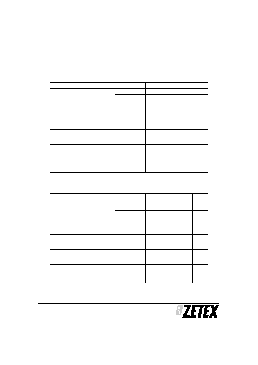
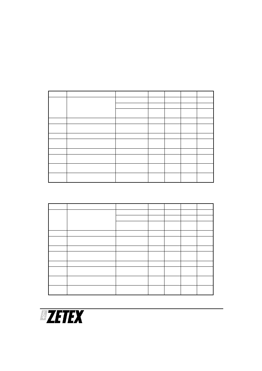
SYMBOL
PARAMETER
CONDITIONS
MIN.
Typ.
MAX.
UNITS
V
O
Output Voltage
5.557
5.7
5.843
V
I
O
=1 to 200mA
5.47
5.93
V
V
in
=7.7 to 20V
I
O
=1 to 100mA
5.47
5.93
V
V
O
Line Regulation
V
in
=7.7 to 20V
10
40
mV
V
O
Load Regulation
I
O
=1 to 200mA
I
O
=1 to 100mA
7
2.5
30
mV
mV
l
q
Quiescent Current
350
600
µ
A
l
q
Quiescent Current Change
I
O
=1 to 200mA
V
in
=7.7 to 20V
100
100
µ
A
µ
A
V
n
Output Noise Voltage
f=10Hz to 10kHz
90
µ
V rms
V
in
/
V
O
Ripple Rejection
V
in
=8.7 to 18V
f=120Hz
48
62
dB
V
in
Input Voltage Required To
Maintain Regulation
7.7
7.4
V
V
O
/
T
Average Temperature
Coefficient of V
O
I
O
=5.0mA
0.15
mV/∞C
ZSR570 TEST CONDITIONS (Unless otherwise stated):T
j
=25∞C, I
O
=100mA, V
in
=9.7V
SYMBOL
PARAMETER
CONDITIONS
MIN.
TYP.
MAX.
UNITS
V
O
Output Voltage
5.85
6
6.15
V
I
O
=1 to 200mA
5.76
6.24
V
V
in
=8 to 20V
I
O
=1 to 100mA
5.76
6.24
V
V
O
Line Regulation
V
in
=8 to 20V
10
40
mV
V
O
Load Regulation
I
O
=1 to 200mA
I
O
=1 to 100mA
7
2.5
30
mV
mV
l
q
Quiescent Current
350
600
µ
A
l
q
Quiescent Current Change
I
O
=1 to 200mA
V
in
=8 to 20V
100
100
µ
A
µ
A
V
n
Output Noise Voltage
f=10Hz to 10kHz
90
µ
V rms
V
in
/
V
O
Ripple Rejection
V
in
=9 to 18V
f=120Hz
48
62
dB
V
in
Input Voltage Required To
Maintain Regulation
8
7.7
V
V
O
/
T
Average Temperature
Coefficient of V
O
I
O
=5.0mA
0.15
mV/∞C
ZSR600 TEST CONDITIONS (Unless otherwise stated): T
j
=25∞C, I
O
=100mA, V
in
=10V
=T
j
= -55 to 125 ∞C
ISSUE 3 - SEPTEMBER 2001
9
ZSR
SERIES
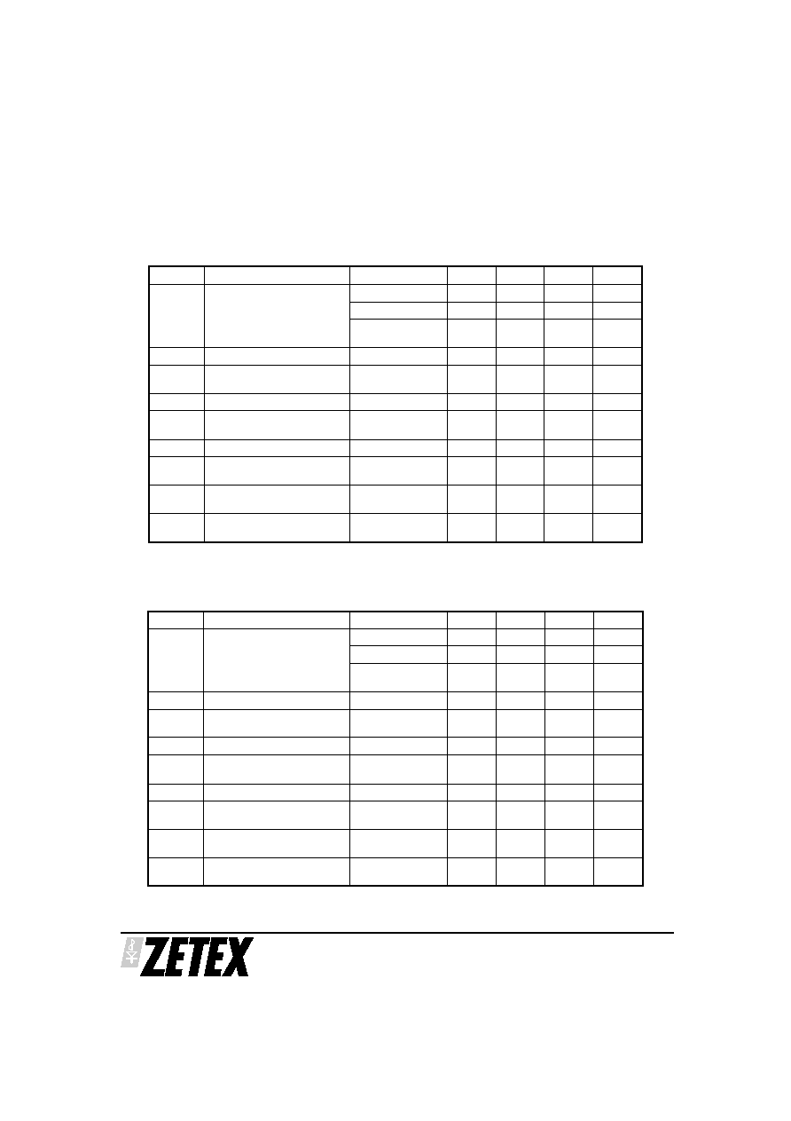
SYMBOL
PARAMETER
CONDITIONS
MIN.
TYP.
MAX.
UNITS
V
O
Output Voltage
5.070
5.2
5.330
V
I
O
=1 to 200mA
4.99
5.41
V
V
in
=7.2 to 20V
I
O
=1 to 100mA
4.99
5.41
V
V
O
Line Regulation
V
in
=7.2 to 20V
10
40
mV
V
O
Load Regulation
I
O
=1 to 200mA
I
O
=1 to 100mA
5
2
25
mV
mV
l
q
Quiescent Current
350
600
µ
A
l
q
Quiescent Current Change
I
O
=1 to 200mA
V
in
=7.2 to 20V
100
100
µ
A
µ
A
V
n
Output Noise Voltage
f=10Hz to 10kHz
75
µ
V rms
V
in
/
V
O
Ripple Rejection
V
in
=8.2 to 18V
f=120Hz
48
62
dB
V
in
Input Voltage Required To
Maintain Regulation
7.2
6.9
V
V
O
/
T
Average Temperature
Coefficient of V
O
I
O
=5.0mA
0.1
mV/∞C
ZSR520 TEST CONDITIONS (Unless otherwise stated): T
j
=25∞C, I
O
=100mA, V
in
=9.2V
=T
j
= -55 to 125 ∞C
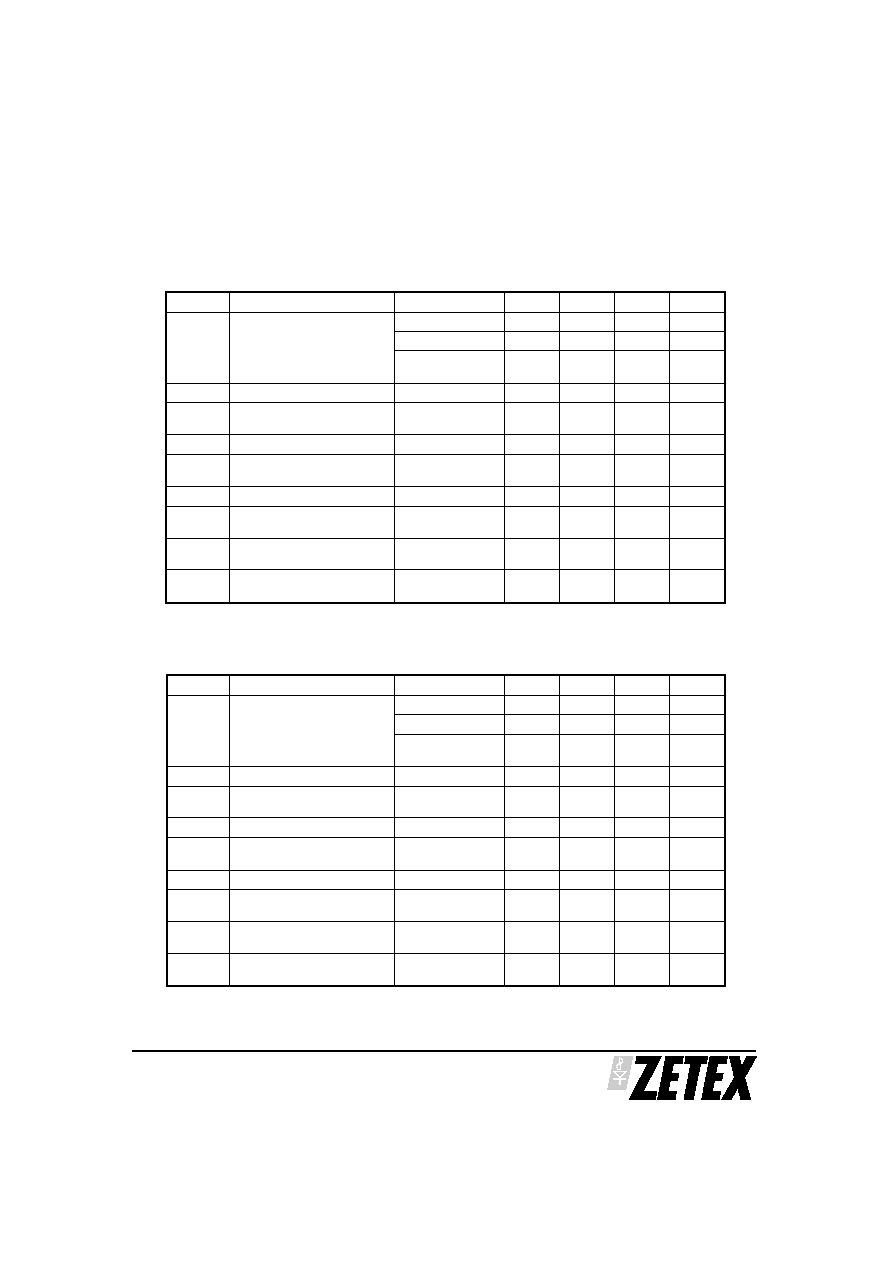
SYMBOL
PARAMETER
CONDITIONS
MIN.
TYP.
MAX.
UNITS
V
O
Output Voltage
4.875
5
5.125
V
I
O
=1 to 200mA
4.8
5.2
V
V
in
=7 to 20V
I
O
=1 to 100mA
4.8
5.2
V
V
O
Line Regulation
V
in
=7 to 20V
10
40
mV
V
O
Load Regulation
I
O
=1 to 200mA
I
O
=1 to 100mA
5
2
25
mV
mV
l
q
Quiescent Current
350
600
µ
A
l
q
Quiescent Current Change
I
O
=1 to 200mA
V
in
=7 to 20V
100
100
µ
A
µ
A
V
n
Output Noise Voltage
f=10Hz to 10kHz
75
µ
V rms
V
in
/
V
O
Ripple Rejection
V
in
=8 to 18V
f=120Hz
48
62
dB
V
in
Input Voltage Required To
Maintain Regulation
7
6.7
V
V
O
/
T
Average Temperature
Coefficient of V
O
I
O
=5.0mA
0.1
mV/∞C
ZSR500 TEST CONDITIONS (Unless otherwise stated): T
j
=25∞C, I
O
=100mA, V
in
=9V
ZSR
SERIES
ISSUE 3 - SEPTEMBER 2001
10
SYMBOL
PARAMETER
CONDITIONS
MIN.
TYP.
MAX.
UNITS
V
O
Output Voltage
8.775
9.0
9.225
V
I
O
=1 to 200mA
8.64
9.36
V
V
in
=11 to 20V
I
O
=1 to 100mA
8.64
9.36
V
V
O
Line Regulation
V
in
=11 to 20V
12
40
mV
V
O
Load Regulation
I
O
=1 to 200mA
I
O
=1 to 100mA
9
3
30
mV
mV
l
q
Quiescent Current
350
600
µ
A
l
q
Quiescent Current Change
I
O
=1 to 200mA
V
in
=11 to 20V
100
100
µ
A
µ
A
V
n
Output Noise Voltage
f=10Hz to 10kHz
150
µ
V rms
V
in
/
V
O
Ripple Rejection
V
in
=12 to 18V
f=120Hz
43
57
dB
V
in
Input Voltage Required To
Maintain Regulation
11
10.7
V
V
O
/
T
Average Temperature
Coefficient of V
O
I
O
=5.0mA
0.25
mV/∞C
ZSR900 TEST CONDITIONS (Unless otherwise stated): T
j
=25∞C, I
O
=100mA, V
in
=13V
=T
j
= -55 to 125∞C
SYMBOL
PARAMETER
CONDITIONS
MIN.
TYP.
MAX.
UNITS
V
O
Output Voltage
8.288
8.5
8.712
V
I
O
=1 to 200mA
8.16
8.84
V
V
in
=10 to 20V
I
O
=1 to 100mA
8.16
8.84
V
V
O
Line Regulation
V
in
=10.5 to 20V
11
40
mV
V
O
Load Regulation
I
O
=1 to 200mA
I
O
=1 to 100mA
8
3
30
mV
mV
l
q
Quiescent Current
350
600
µ
A
l
q
Quiescent Current Change
I
O
=1 to 200mA
V
in
=10.5 to 20V
100
100
µ
A
µ
A
V
n
Output Noise Voltage
f=10Hz to 10kHz
115
µ
V rms
V
in
/
V
O
Ripple Rejection
V
in
=11.5 to 18V
f=120Hz
44
60
dB
V
in
Input Voltage Required To
Maintain Regulation
10.5
10.2
V
V
O
/
T
Average Temperature
Coefficient of V
O
I
O
=5.0mA
0.25
mV/∞C
ZSR850 TEST CONDITIONS (Unless otherwise stated): T
j
=25∞C, I
O
=100mA, V
in
=12.5V

ISSUE 3 - SEPTEMBER 2001
ZSR
SERIES
ZSR330 ZSR500 ZSR600
ZSR800 ZSR1000
11
TYPICAL CHARACTERISTICS

ZSR
SERIES
ZSR330 ZSR500 ZSR600
ZSR800 ZSR1000
ISSUE 3 - SEPTEMBER 2001
12
4-38
TYPICAL CHARACTERISTICS
ISSUE 3 - SEPTEMBER 2001
13
ZSR
SERIES
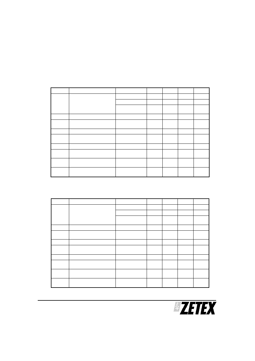
SYMBOL
PARAMETER
CONDITIONS
MIN.
TYP.
MAX.
UNITS
V
O
Output Voltage
7.8
8
8.2
V
I
O
=1 to 200mA
7.68
8.32
V
V
in
=10 to 20V
I
O
=1 to 100mA
7.68
8.32
V
V
O
Line Regulation
V
in
=10 to 20V
11
40
mV
V
O
Load Regulation
I
O
=1 to 200mA
I
O
=1 to 100mA
8
3
30
mV
mV
l
q
Quiescent Current
350
600
µ
A
l
q
Quiescent Current Change I
O
=1 to 200mA
V
in
=10 to 20V
100
100
µ
A
µ
A
V
n
Output Noise Voltage
f=10Hz to 10kHz
115
µ
V rms
V
in
/
V
O
Ripple Rejection
V
in
=11 to 18V
f=120Hz
44
60
dB
V
in
Input Voltage Required To
Maintain Regulation
10
9.7
V
V
O
/
T
Average Temperature
Coefficient of V
O
I
O
=5.0mA
0.25
mV/∞C
ZSR800 TEST CONDITIONS (Unless otherwise stated): T
j
=25∞C, I
O
=100mA, V
in
=12V
=T
j
= -55 to 125∞C
SYMBOL
PARAMETER
CONDITIONS
MIN.
TYP.
MAX.
UNITS
V
O
Output Voltage
6.825
7
7.175
V
I
O
=1 to 200mA
6.72
7.28
V
V
in
=9 to 20V
I
O
=1 to 100mA
6.72
7.28
V
V
O
Line Regulation
V
in
=9 to 20V
10
40
mV
V
O
Load Regulation
I
O
=1 to 200mA
I
O
=1 to 100mA
5
2
25
mV
mV
l
q
Quiescent Current
350
600
µ
A
l
q
Quiescent Current Change
I
O
=1 to 200mA
V
in
=9 to 20V
100
100
µ
A
µ
A
V
n
Output Noise Voltage
f=10Hz to 10kHz
75
µ
V rms
V
in
/
V
O
Ripple Rejection
V
in
=10 to 18V
f=120Hz
48
62
dB
V
in
Input Voltage Required To
Maintain Regulation
9
8.7
V
V
O
/
T
Average Temperature
Coefficient of V
O
I
O
=5.0mA
0.1
mV/∞C
ZSR700 TEST CONDITIONS (Unless otherwise stated): T
j
=25∞C, I
O
=100mA, V
in
=11V

ISSUE 3 - SEPTEMBER 2001
14
ZSR
SERIES
ZSR485 ZSR520 ZSR700
ZSR850 ZSR1200
4-38
Output Voltage Temperature Coefficient
Temperature (∞C)
0
25
75
50
Ou
tput
V
o
l
t
a
g
e
(V)
-50 -25
100125
4.90
5.15
5.20
5.25
4.80
4.85
Io = 10mA
Vin = Vout + 4v
ZSR520
ZSR485
Output Voltage Temperature Coefficient
Temperature (∞C)
0
25
75
50
-50 -25
100 125
7.10
8.55
8.45
8.50
6.90
7.00
Output Voltage Temperature Coefficient
Temperature (∞C)
0 25
75
50
Ou
tput
V
o
l
t
a
g
e
(V)
-50 -25
100125
12.10
12.00
11.90
12.05
11.95
Io = 10mA
Vin = Vout + 4v
ZSR1200
Quiescent Current v Temperature
Temperature (∞C)
0
25
75
50
-50 -25
100 125
500
450
400
350
300
Peak Output Current v Temperature
Temperature (∞C)
0
25
75
50
0
Shor
t-c
irc
uit
O
utpu
t
Curr
ent
(m
A)
100
500
400
300
200
-50 -25
100 125
Vo= 0
Vin= 10v
Drop-Out Votlage v Temperature
Temperature (∞C)
0
25
75
50
0
0.5
2.5
2.0
1.5
1.0
-50 -25
100125
Vo= 0
Vin= 10v
Io = 10mA
Vin = Vout + 4v
ZSR850
ZSR700
TYPICAL CHARACTERISTICS
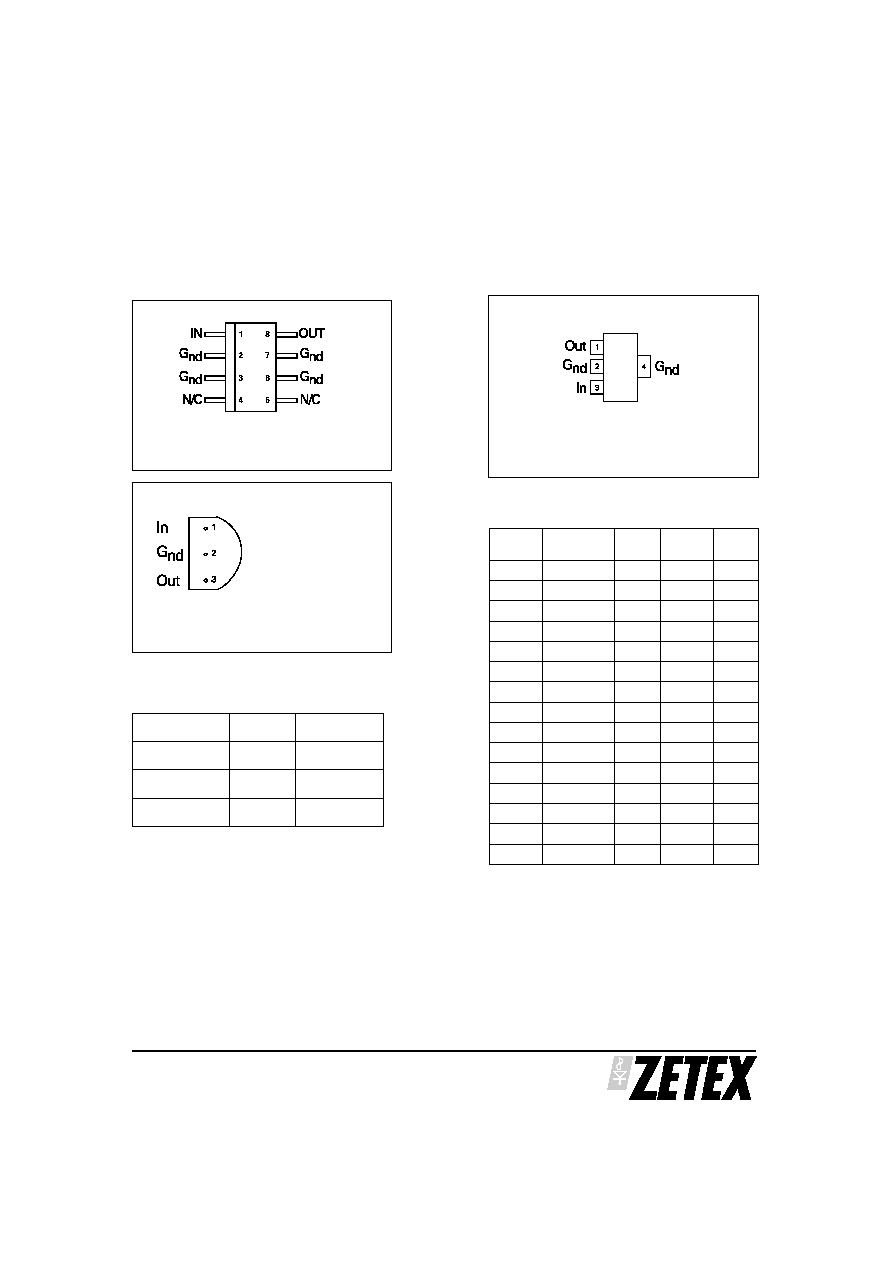
CONNECTION DIAGRAMS
ISSUE 3 - SEPTEMBER 2001
15
ZSR
SERIES
SO8
Package Suffix ≠ N8
Top View
TO92
Package Suffix ≠ C
Bottom View
SOT223
Package Suffix ≠ G
Top View ≠
Connect pin 4 to pin 2 or leave pin 4
electrically isolated
Part No
Package
Partmark
ZSR
s C
TO92
ZSR
s
ZSR
s G
SOT223
ZSR
s
ZSR
s N8
SO8
ZSR
s
s Voltage Option
eg 3V device in TO92 package
part number ZSR300C
part marked ZSR300 *
eg 12V device in SOT223 package
part number ZSR1200G
part marked ZSR1200 *
eg 5V device in SO8 package
part number ZSR500N8
part marked ZSR500 *
ORDERING INFORMATION
Voltage Voltage
Option
s
TO92
SOT223 SO8
2.85V
285
3
3
3
3.0V
300
3
3
3
3.3V
330
3
3
3
4.0V
400
3
3
3
4.85V
485
3
3
3
5.0V
500
3
3
3
5.2V
520
3
3
3
5.7V
570
3
3
3
6.0V
600
3
3
3
7.0V
700
3
3
3
8.0V
800
3
3
3
8.5V
850
3
3
3
9.0V
900
3
3
3
10.0V
1000
3
3
3
12.0V
1200
3
3
3
OPTIONS
* NOTE: Exception. ZSR1000 part mark
is ZSR100 for all package options

ZSR
SERIES
ISSUE 3 - SEPTEMBER 2001
16
Q14
Q16
Q17
Q11
R7
R4
R3
Q18
Q19
R5
Q20
Q13
Q25
Q4
Q5
Q1
R1
Q3
C1
Q6
Q7
R2
Q8
R14
Q10
R9
R13
V
in
V
out
Gnd
R6
Q9
Q12
Q21
SCHEMATIC DIAGRAM
FixedOutputRegulator
AdjustableOutputRegulator
Input
Output
Gnd
ZR78L***
Input
Output
Gnd
ZR78L***
R1
R2
Iq
Vo=Vreg+(V reg/R1+Iq)R2
CurrentRegulator
Input
Output
ZR78L***
R1
Iq
I
O
=(Vreg/R1) + 1q
APPLICATIONS

ISSUE 3 - SEPTEMBER 2001
ZSR
SERIES
17
ZSR485 ZSR520 ZSR700
ZSR850 ZSR1200
4-
Line Transient Response
Time (µs)
20
30
50
40
Outpu
t
V
oltage
Deviation
(V)
+0.2
0
0
10
-0.2
Vo+4
Vo+9
Io= 100mA
Cout= 0
dVin/dt= 5v/us
Input
Voltage
Output Voltage
Deviation
Load Transient Response
Time (us)
20
30
50
40
Outpu
t
V
oltage
Deviation
(V)
+0.2
0
0
10
-0.2
0
100mA
Load Current
Output Voltage
Deviation
Vin= Vout+4v
Cout= 0
dIo/dt= 1A/us
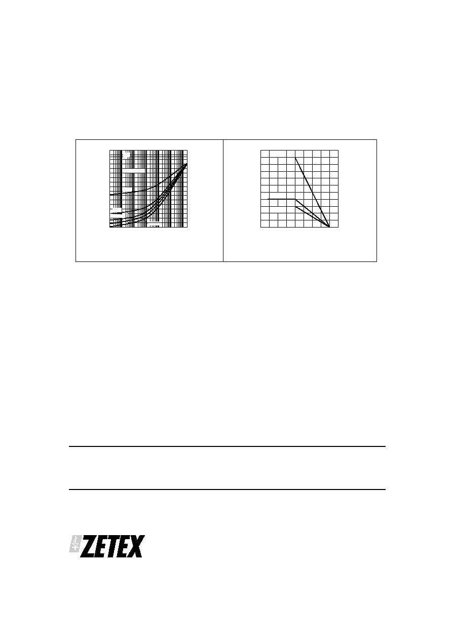
Thermal Resistance v Pulse Width
Pulse Width (s)
1m
100m
0
60
1
10
10m
20
40
80
100
120
140
160
D=1
D=0.5
D=0.2
D=0.1
D=0.05
D=0
TO92 PACKAGE
Thermal Resistance v Pulse Width
Pulse Width (s)
1m
100m
Thermal
Resistance
(
∞
C/W)
0
24
1
10
10m
8
16
32
40
48
SOT223 PACKAGE
D=1
D=0.5
D=0.2
D=0.1
D=0.05
D=0
Output Impedance v Frequency
Frequency (Hz)
10
1k
Outpu
t
Impedance
(Ohms)
0.01
10
10k
100k
100
0.1
1
Io= 100mA
Vin= Vout+4v
ZSR1200
ZSR850
ZSR700
ZSR520
ZSR485
Ripple Rejection v Ripple Frequency
Frequency (Hz)
100
10k
Open
Loop
Gain
(dB)
0
50
100k
1M
1k
40
30
20
10
70
60
80
90
ZSR485
ZSR520
ZSR700
ZSR850
ZSR1200
Io= 100mA
Vin= Vout+4v
Vin= 200mV Pk/Pk
Thermal
Resistance
(
∞
C/W)
TYPICAL CHARACTERISTICS
ISSUE 3 - SEPTEMBER 2001
18
Zetex plc
Fields New Road
Chadderton
Oldham, OL9 8NP
United Kingdom
Telephone (44) 161 622 4422
Fax: (44) 161 622 4420
Zetex GmbH
Streitfeldstraþe 19
D-81673 M¸nchen
Germany
Telefon: (49) 89 45 49 49 0
Fax: (49) 89 45 49 49 49
Zetex Inc
Suite 315
700 Veterans Memorial Highway
Hauppauge NY11788
USA
Telephone: (631) 360 2222
Fax: (631) 360 8222
Zetex (Asia) Ltd
3701-04 Metroplaza, Tower 1
Hing Fong Road
Kwai Fong, Hong Kong
China
Telephone: (852) 26100 611
Fax: (852) 24250 494
These offices are supported by agents and distributors in major countries world-wide.
This publication is issued to provide outline information only which (unless agreed by the Company in writing) may not be used, applied or
reproduced for any purpose or form part of any order or contract or be regarded as a representation relating to the products or services
concerned. The Company reserves the right to alter without notice the specification, design, price or conditions of supply of any product or
service.
For the latest product information, log on to
www.zetex.com
© Zetex plc 2001
ZSR
SERIES
Thermal Resistance v Pulse Width
Pulse Width (s)
1m
100m
Therm
al
Re
sistance
(
∞
C/
W)
0
60
1
10
10m
20
40
80
100
120
140
160
SO8 PACKAGE
D=0.2
D=0.1
D=0.05
D=0
Power dissipation Derating
Ambient Temperature (∞C)
-50
0
M
axim
um
Power
Dissipation
(W)
0
1.0
25 50
-25
0.8
0.6
0.4
0.2
1.4
1.2
1.6
1.8
75 100125
2.0
SOT223
SO8
TO92
100µ
100
D=1
D=0.5
TYPICAL CHARACTERISTICS