GENERAL DATA
Life Expectancy
Minimum operations
Mechanical
1 x 10
6
Electrical
1 x 10
4
at 100 A 240 VAC Res.
Set and Reset
Pulse Duration
36 ms minimum
Set Time (typical)
12 ms at nominal coil voltage
Reset Time (typical)
6 ms at nominal coil voltage
Dielectric Strength
4000 Vrms coil to contact
(at sea level for 1 min.) 2000 Vrms between open contacts
Insulation
1000 megohms min. at 20∞C, 500 VDC,
Resistance
50% RH
Creepage Distance
8 mm
Ambient Temperature
At nominal coil voltage
Operating
-40∞C (-40∞F) to 70∞C (158∞F)
Storage
-40∞C (-40∞F) to 105∞C (221∞F)
Vibration
0.062" DA at 10≠55 Hz
Shock
Operating
10 g, 11 ms,
1
/
2
sine (no false operation)
Non-Operating 100 g, 11 ms,
1
/
2
sine (no damage)
Enclosure
P.B.T. polyester
Terminals
Tinned copper alloy
P. C. (coil), heavy tabs (power)
Max. Solder Temp.
270∞C (518∞F)
Max. Solder Time
5 seconds
Weight
82 grams
NOTES
1. All values at 20∞C (68∞F).
2. Relay may pull in with less than "Must Operate" value.
3. Specifications subject to change without notice.
4. Allow suitable slack on leads when wiring, and do not subject the
terminals to excessive force.
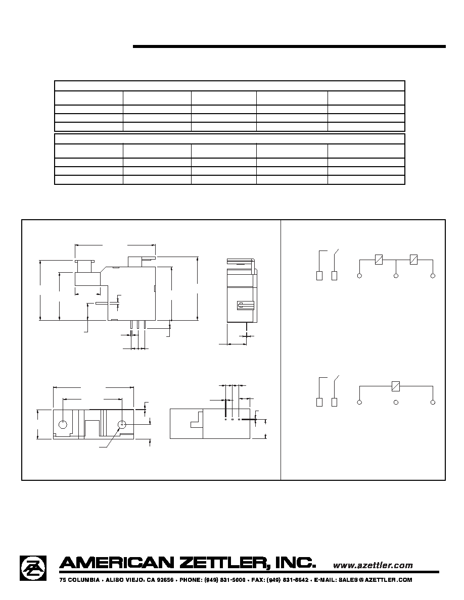
AZ2510
10/28/03W
100 AMP LATCHING
POWER RELAY
FEATURES
∑ 100 Amp switching
∑ Heavy loads to 24000 VA
∑ 4 kV dielectric
∑ Meets 8 mm creepage
∑ Mechanical position indicator which may be also used
for manual operation or to actuate a micro-switch
∑ UL, CUR pending
CONTACTS
Arrangement
SPST (1 Form A)
Ratings
Resistive load:
Max. switched power: 24000 VA
Max. switched current: 100 A
Max. switched voltage: 400 VAC
Rated Load
UL, CUR
100 A at 240 VAC, 10k cycles, Resistive
Material
Silver tin oxide
Resistance
< 2 milliohms initially
(24 V, 1 A voltage drop method)
COIL
Power
At Pickup Voltage
1.44 W single coil
(typical)
2.88 W dual coil
Temperature
Max. 105∞C (2221∞F)