ZETTLER
electronics GmbH
Fax +49 89 800 97 200 www.ZETTLERelectronics.com
office@ZETTLERelectronics.com
0
97
800
89
+49
Tel.
Germany
Puchheim,
D-82178
Junkersstrasse 3,
2004-07-29
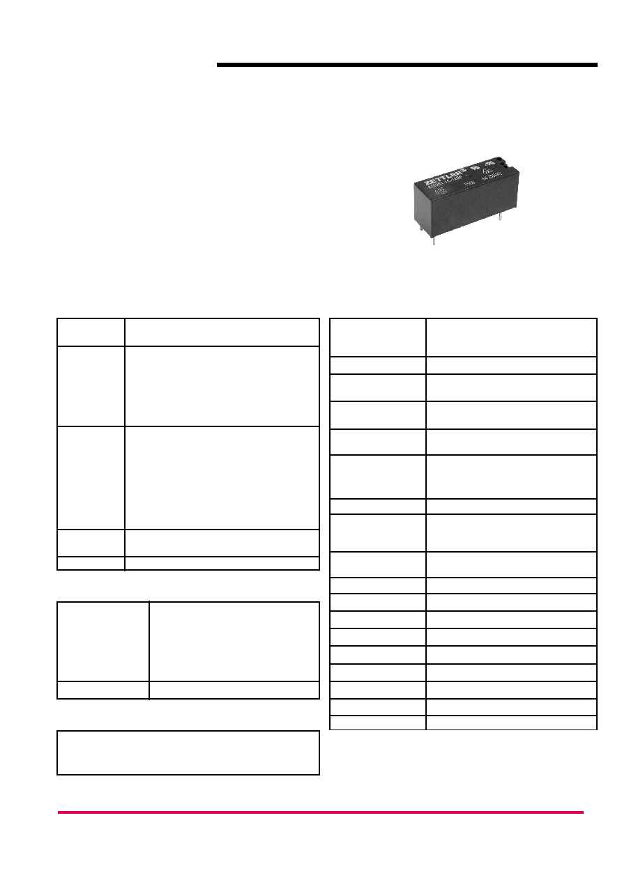
AZ6961
10 AMP SUBMINIATURE
POWER RELAY
FEATURES
∑ High sensitivity, 120 mW pickup
∑ Dielectric strength 5000 Vrms
∑ Isolation spacing greater than 8 mm
∑ 10 Amp switching capability
∑ Epoxy sealed version available
∑ Reinforced insulation, EN 60730-1 (VDE 0631, part 1)
∑ UL, CUR file E43203
∑ VDE file 131637
GENERAL DATA
Life Expectancy
Minimum operations
Mechanical
1 x 10
7
Electrical
1 x 10
5
at 8 A 250 VAC res.
Operate Time (typical)
7 ms at nominal coil voltage
Release Time (typical)
3 ms at nominal coil voltage
(with no coil suppression)
Dielectric Strength
5000 Vrms coil to contact
(at sea level for 1 min.) 1000 Vrms between open contacts
Insulation
1000 megohms min. at 20∞C, 500 VDC,
Resistance
50% RH
Insulation
C250
(according to
Overvoltage category: III
DIN VDE 0110,
Pollution degree: 3
IEC 60664-1)
Nominal voltage: 250 VAC
Dropout
Greater than 10% of nominal coil voltage
Ambient Temperature
At nominal coil voltage
Operating
-40∞C (-40∞F) to 85∞C (185∞F)
Storage
-40∞C (-40∞F) to 105∞C (221∞F)
Vibration
Break Contact: 5 g at 10 ...500 Hz
Make Contact: 20 g at 10...500 Hz
Shock
10 g
Enclosure
P.B.T. polyester, UL94 V-O
Terminals
Tinned copper alloy, P.C.
Max. Solder Temp.
270∞C (518∞F)
Max. Solder Time
5 seconds
Max. Solvent Temp.
80∞C (176∞F)
Max. Immersion Time
30 seconds
Weight
8 grams
Packing unit in pcs
20 per plastic tube / 1000 per carton box
CONTACTS
Arrangement
SPDT (1 Form C)
SPST (1 Form A)
Ratings
Resistive load:
Max. switched power: 240 W or 2500 VA
Max. switched current: 10 A
Max. switched voltage: 240* VDC or 440 VAC
*
Note: If switching voltage is greater than 30 VDC,
special precautions must be taken.
Please contact the factory.
Rated Load
UL, CUR
10 A at 250 VAC resistive [1]
8 A at 30 VDC / 250 VAC [1]
8 A at 30 VDC / 250 VAC, 100k cycles [2]
B300 Pilot Duty [1]
R300 Pilot Duty [1]
VDE
8 A at 250 VAC resistive, [1], [2] and [3]
[1] Silver cadmium oxide, [2] Silver tin oxide,
[3] Silver nickel
Material
Silver cadmium oxide, silver tin oxide
or silver nickel, gold plating available
Resistance
< 100 milliohms initially
NOTES
1. All values at 20∞C (68∞F).
2. Relay may pull in with less than "Must Operate" value.
3. Specifications subject to change without notice.
COIL
Power
At Pickup Voltage
120 mW
(typical)
140 mW (60 VDC coil)
Max. Continuous
1.2 W at 20∞C (68∞F) ambient
Dissipation
Temperature Rise
20∞C (36∞F) at nominal coil voltage
Temperature
Max. 130∞C (266∞F)

MECHANICAL DATA
2004-07-29
ZETTLER
electronics GmbH
Fax +49 89 800 97 200 www.ZETTLERelectronics.com
office@ZETTLERelectronics.com
0
97
800
89
+49
Tel.
Germany
Puchheim,
D-82178
Junkersstrasse 3,
AZ6961
RELAY ORDERING DATA
COIL SPECIFICATIONS
ORDER NUMBER*
Nominal Coil
Must Operate
Max. Continuous
Coil Resistance
1 Form A
1 Form C
VDC
VDC
VDC
Ohm
(SPST-NO)
(SPDT)
5
3.5
11.6
113 ± 10%
AZ6961≠1A≠5D
AZ6961≠1C≠5D
6
4.2
14.0
164 ± 10%
AZ6961≠1A≠6D
AZ6961≠1C≠6D
9
6.3
21.1
360 ± 10%
AZ6961≠1A≠9D
AZ6961≠1C≠9D
12
8.4
27.2
617 ± 10%
AZ6961≠1A≠12D
AZ6961≠1C≠12D
15
10.5
38.0
800 ± 10%
AZ6961≠1A≠15D
AZ6961≠1C≠15D
24
16.8
53.1
2,350 ± 10%
AZ6961≠1A≠24D
AZ6961≠1C≠24D
48
33.6
107.3
9,600 ± 15%
AZ6961≠1A≠48D
AZ6961≠1C≠48D
60
42.0
122.4
12,500 ± 15%
AZ6961≠1A≠60D
AZ6961≠1C≠60D
*
Add suffix "E" to "1A" or "1C" for silver tin oxide contacts. Add suffix "B" to "1A" or "1C" for silver nickel contacts.
Add suffix "E" at the end of order number for sealed version. Add suffix "A" for gold plated contacts.
1 FORM C
VIEWED TOWARD TERMINALS
FORM C VERSION
CIRCUIT DIAGRAM
PC BOARD LAYOUT
FORM A VERSION
1
4
2
3
5
1 FORM A
1
3
2
4
[3.2]
.126
.050
[1.3]
[¯
1.3]
.298
[7.56]
.744
[18.9]
.116
[2.95]
.198
[5.04]
4 x ¯
.051
.126
[3.2]
.870
[22.1]
[¯
1.3]
5 x ¯
.051
[1.3]
.050
[1.57]
.062
[7.56]
.298
1 FORM A
1 FORM C
VIEWED TOWARD TERMINALS
[28.75]
1.132 Max.
[12.55]
.494 Max.
[3.6]
.142
[0.8]
3 x .031
[0.4]
3 x .016
[0.3]
.012
[10.35]
.408 Max.
[¯
0.5]
2 x ¯
.020
.012
[0.3]
2 x .031
[0.8]
[0.4]
2 x .016
.142
[3.6]
[¯
0.5]
2 x ¯
.020
[28.75]
1.132 Max.
[12.55]
.494 Max.
[10.35]
.408 Max.
Dimensions in inches with metric equivalents in parentheses. Tolerance: ± .010"
Percent of Nominal Coil Voltage at 20
∞
C
60%
80% 100% 120% 140%
160% 180% 200% 220%
Coil Temperature Rise
∞
C
160
150
140
130
120
110
100
90
80
70
60
50
40
30
20
10
0
10A
0A
10
20
30
40
50
60
70
80 90
10
0
200
300
400
500
600
700
800
900
10
0
0
.1
.2
.3
.4
.5
.6
.7
.8
.9
1.0
2.0
3.0
4.0
5.0
6.0
7.0
8.0
9.0
10.0
CURRENT
VOLTAGE
DC Resistive
Load
AC Resistive
Load
Coil Temperature Rise
Maximum Switching Capacity