GENERAL DATA
Life Expectancy
Minimum operations
Mechanical
1 x 10
7
Electrical
1 x 10
5
at 16 A 240 VAC Res.
Operate Time (typical)
20 ms at nominal coil voltage
Release Time (typical)
10 ms at nominal coil voltage
(with no coil suppression)
Dielectric Strength
5000 Vrms coil to contact
(at sea level for 1 min.) 1000 Vrms between open contacts
Insulation
1000 megohms min. at 20∞C
Resistance
500 VDC 50% RH
Dropout
Greater than 10% of nominal coil voltage
Ambient Temperature
At nominal coil voltage
Operating
-40∞C (-40∞F) to 85∞C (185∞F)
Storage
-40∞C (-40∞F) to 130∞C (266∞F)
Vibration
0.062" DA at 10≠55 Hz
Shock
10 g
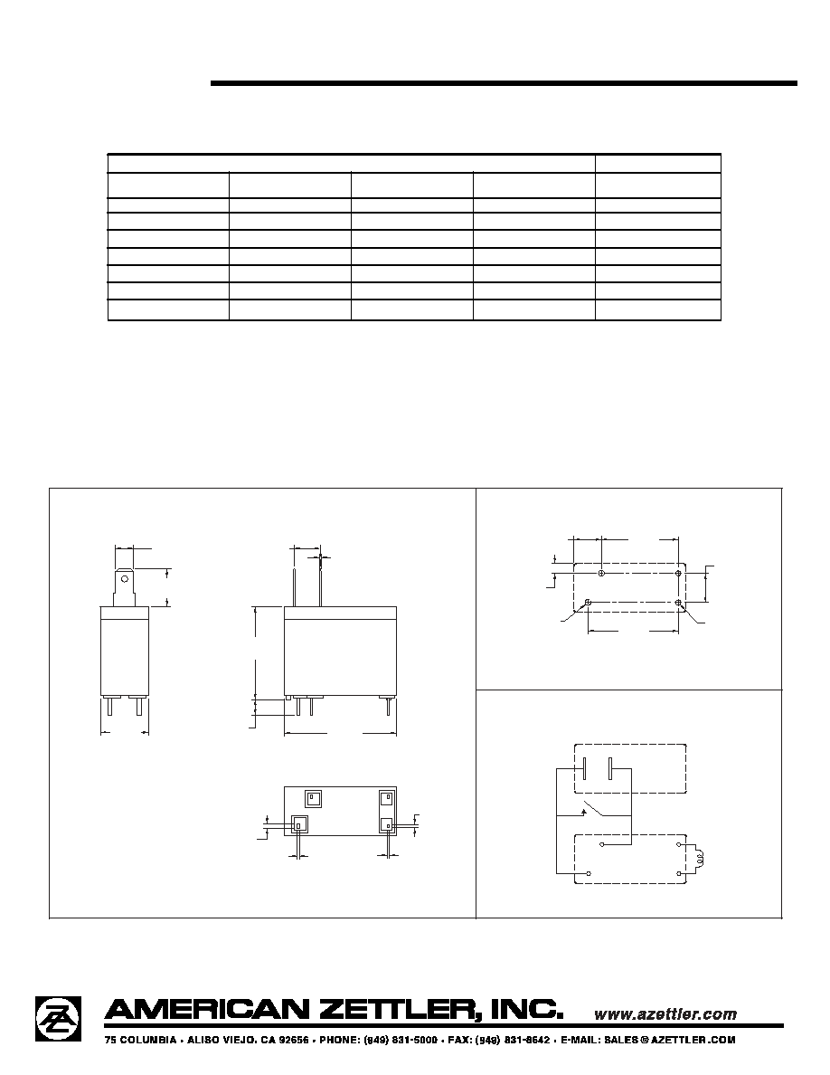
Enclosure
P.B.T. polyester
Terminals
Tinned copper alloy, P. C. and Quick Connects
Note: Allow suitable slack on leads when wiring, and do
not subject the terminals to excessive force.
Max. Solder Temp.
270∞C (518∞F)
Max. Solder Time
5 seconds
Weight
13 grams
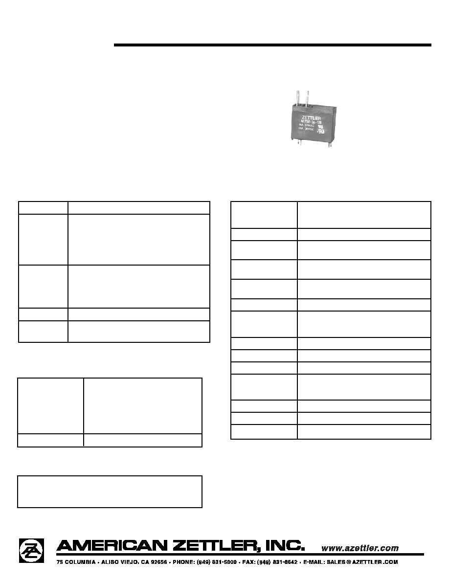
AZ756
8/8/03W
20 AMP MINIATURE
POWER RELAY
FEATURES
∑ Dielectric strength 5000 Vrms
∑ Low cost
∑ 20 Amp switching -- single pole contacts
∑ Isolation spacing greater than 8mm
∑ UL Class B insulation system standard
Class F available
∑ UL, CUR file E43203, TÐV R50029277
CONTACTS
Arrangement
SPST - N.O.
Ratings
Resistive load:
Max. switched power: 480 W or 4000 VA
Max. switched current: 20 A
Max. switched voltage: 150* VDC or 277 VAC
*
Note: If switching voltage is greater than 30 VDC, special
precautions must be taken. Please contact the factory.
Rated Load
20 A at 125 VAC Resistive, 100k cycles
UL, CUR
16 A at 250 VAC Resistive, 100k cycles
16 A at
30 VDC Resistive, 100k cycles
TÐV
16 A at 250 VAC Resistive, 100k cycles
16 A at
30 VDC Resistive, 50k cycles
Material
Silver tin oxide
Resistance
< 50 milliohms initially
(24 V, 1 A voltage drop method)
COIL
Power
At Pickup Voltage
340 mW
(typical)
Max. Continuous
1.5 W at 20∞C (68∞F) ambient
Dissipation
1.1 W at 40∞C (104∞F) ambient
Temperature Rise
41∞C (74∞F) at nominal coil voltage
Temperature
Max. 130∞C (266∞F)
NOTES
1. All values at 20∞C (68∞F).
2. Relay may pull in with less than "Must Operate" value.
3. Specifications subject to change without notice.