GENERAL DATA
Life Expectancy
Minimum operations
Mechanical
1 x 10
7
Electrical
1 x 10
5
at 16 A 250 VAC Res.
Operate Time (typical)
8 ms at nominal coil voltage
Release Time (typical)
4 ms at nominal coil voltage
(with no coil suppression)
Dielectric Strength
5000 Vrms coil to contact
(at sea level for 1 min.) 1000 Vrms between open contacts
Surge
10000 V contact to coil
(1.2 x 50 µ s)
Insulation
1000 megohms min. at 20∞C, 500 VDC,
Resistance
50% RH
Dropout
Greater than 5% of nominal coil voltage
Ambient Temperature
At nominal coil voltage
Operating
-40∞C (-40∞F) to 70∞C (158∞F)
Storage
-40∞C (-40∞F) to 130∞C (266∞F)
Vibration
0.062" DA at 10≠55 Hz
Shock
Operating
10 g, 11 ms,
1
/
2
sine (no false operation)
Non-Operating 100 g, 11 ms,
1
/
2
sine (no damage)
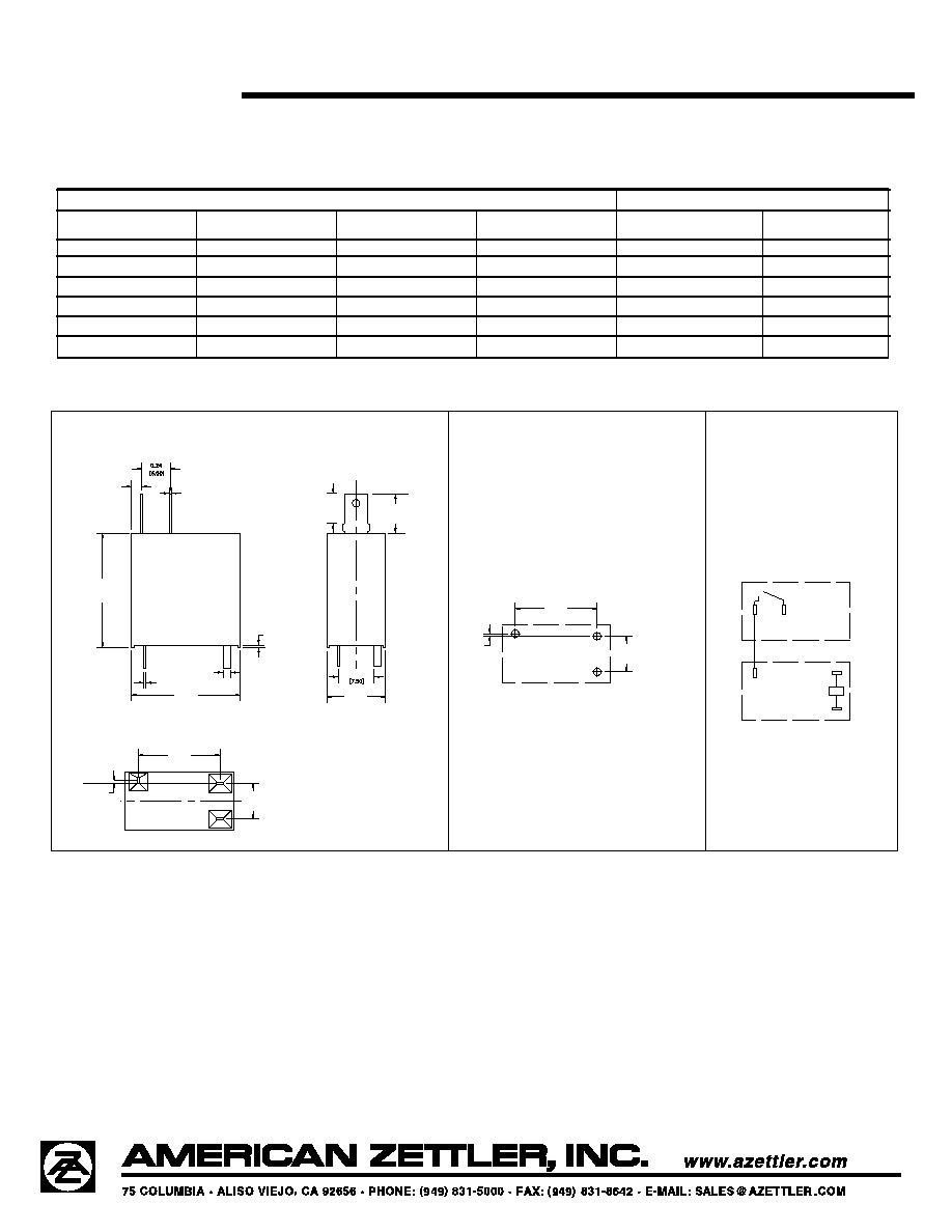
Enclosure
P.B.T. polyester
Terminals
Tinned copper alloy
P. C. & quick connect
Note: Allow suitable slack on leads when wiring,
and do not subject the terminals to excessive
force.
Max. Solder Temp.
270∞C (518∞F)
Max. Solder Time
5 seconds
Max. Solvent Temp.
80∞C (176∞F)
Max. Immersion Time
30 seconds
Weight
4.6 grams
COIL
Power
At Pickup Voltage
245 mW
(typical)
Max. Continuous
Dissipation
.85 W at 20∞C (68∞F) ambient
Temperature Rise
55∞C (99∞F) at nominal coil voltage
Temperature
Max. 130∞C (266∞F) Class B
Max. 155∞C (311∞F) Class F
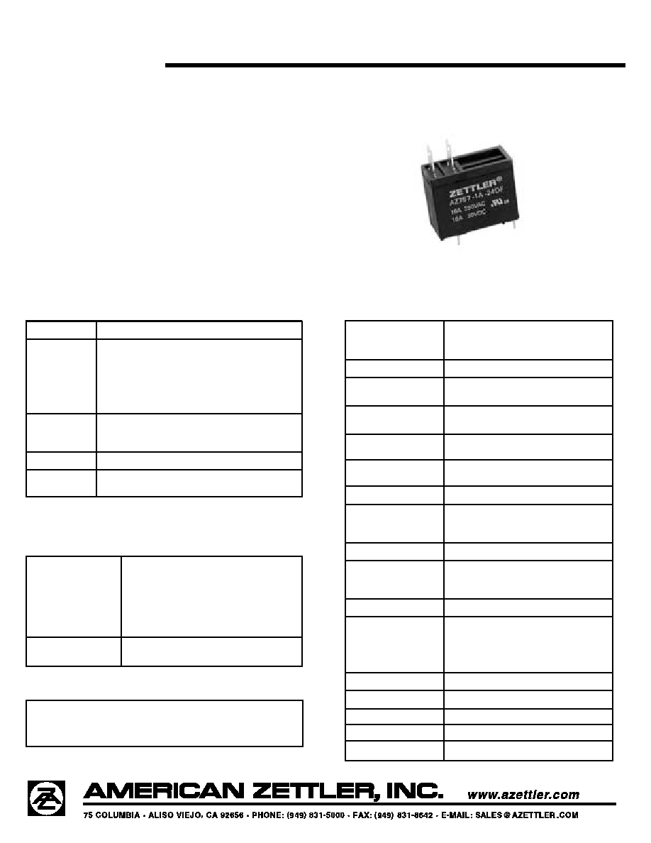
AZ757
3/27/03W
16 AMP MINIATURE
POWER RELAY
FEATURES
∑ Low cost
∑ 16 Amp switching
∑ Class B (130∞C) insulation system standard,
Class F (155∞C) system available
∑ Quick connect terminals
∑ Epoxy sealed for automatic wave soldering
∑ 10 kV Surge
∑ UL, CUR file E43203
CONTACTS
Arrangement
SPST (1 Form A)
Ratings
Resistive load:
Max. switched power: 480 W or 4000 VA
Max. switched current: 16 A
Max. switched voltage: 150* VDC or 400 VAC
*
Note: If switching voltage is greater than 30 VDC, special
precautions must be taken. Please contact the factory.
Rated Load
UL, CUR
16 A at 250 VAC, general use
16 A at 30 VDC resistive
Material
Silver tin oxide
Resistance
< 50 milliohms initially
(24 V, 1 A voltage drop method)
NOTES
1. All values at 20∞C (68∞F).
2. Relay may pull in with less than "Must Operate" value.
3. Specifications subject to change without notice.