
GENERAL DATA
Life Expectancy
Minimum operations
Mechanical
1 x 10
7
Electrical
1 x 10
5
at 1.0 A 120 VAC Res.
Operate Time (typical)
6 ms at nominal coil voltage
Release Time (typical)
5 ms at nominal coil voltage
(with no coil suppression)
Dielectric Strength
1500 Vrms contact to coil
(at sea level for 1 min.)
500 Vrms between open contacts
1500 Vrms contact set to contact set
Insulation Resistance
1000 megohms min. at 20∞C, 500 VDC,
50% RH
Dropout
Greater than 10% of nominal coil voltage
Ambient Temperature
At nominal coil voltage
Operating
-40∞C (-40∞F) to 70∞C (158∞F) standard
-40∞C (-40∞F) to 80∞C (176∞F) sensitive
-40∞C (-40∞F) to 85∞C (185∞F) ultra-sensitive
Storage
-40∞C (-40∞F) to 105∞C (221∞F)
Vibration
1.5 mm DA at 10≠55 Hz
Shock
50 g 11 ms
1
/
2
sine
Enclosure
P.B.T. polyester
Terminals
Tinned copper alloy
Max. Solder Temp.
270∞C (518∞F)
Max. Solder Time
5 seconds
Max. Solvent Temp.
80∞C (176∞F)
Max. Immersion Time
30 seconds
COIL
Power
At Pickup Voltage
180 mW standard
(typical)
100 mW sensitive
84 mW ultra-sensitive
Max. Continuous
1.2 W at 20∞C (68∞F)
Dissipation
Temperature Rise
34∞C (61∞F) standard
23∞C (41∞F) sensitive
19∞C (34∞F) ultra-sensitive
Temperature
Max. 105∞C (221∞F)
CONTACTS
Arrangement
DPDT (2 Form C)
Ratings
Resistive load:
Max. switched power: 24 W or 125 VA
Max. switched current: 1 A
Max. switched voltage: 150 VDC or 220 VAC
Rated Load
UL
1.0 A at 24 VDC
1.0 A at 125 VAC
Material
Silver, gold plated
Resistance
< 50 milliohms initially
AZ826
10/29/02W
SUBMINIATURE
ULTRA-SENSITIVE
DIP RELAY
FEATURES
∑ Low profile for compact board spacing
∑ DC coils to 24 VDC
∑ Bifurcated crossbar contacts
∑ Ultra-sensitivity, 84 mW pickup
∑ Life expectancy to 10 million operations
∑ High switching capacity, 24 W, 125 VA
∑ Fits standard 16 pin IC socket
∑ Epoxy sealed for automatic wave soldering and cleaning
∑ Meets FCC Part 68.302 1500 V lightning surge
∑ Meets FCC Part 68.304 1000 V dielectric
∑ UL, CUR file E43203
NOTES
1. All values at 20∞C (68∞F).
2. Relay may pull in with less than "Must Operate" value.
3. Other coil resistances and sensitivities available upon request.
4. Specifications subject to change without notice.
RELAY ORDERING DATA
STANDARD COIL SPECIFICATIONS
Nominal Coil
Max. Continuous
Coil Resistance
Must Operate
ORDER NUMBER
VDC
VDC
± 10%
VDC
3
5.5
25
2.1
AZ826-2C-3DME
5
9.2
70
3.5
AZ826≠2C≠5DME
6
11.0
100
4.2
AZ826≠2C≠6DME
9
16.4
225
6.3
AZ826≠2C≠9DME
12
21.9
400
8.4
AZ826≠2C≠12DME
24
43.8
1600
16.8
AZ826≠2C≠24DME
SENSITIVE COIL SPECIFICATIONS
Nominal Coil
Max. Continuous
Coil Resistance
Must Operate
ORDER NUMBER
VDC
VDC
± 10%
VDC
3
7.3
45
2.1
AZ826-2C-3DSE
5
12.2
125
3.5
AZ826≠2C≠5DSE
6
14.7
180
4.2
AZ826≠2C≠6DSE
9
22.0
405
6.3
AZ826≠2C≠9DSE
12
29.0
720
8.4
AZ826≠2C≠12DSE
24
52.3
2880
16.8
AZ826≠2C≠24DSE
ULTRA-SENSITIVE COIL SPECIFICATIONS
Nominal Coil
Max. Continuous
Coil Resistance
Must Operate
ORDER NUMBER
VDC
VDC
± 10%
VDC
3
8.5
60
2.3
AZ826≠2C≠3DSSE
4.5
12.7
135
3.4
AZ826≠2C≠4.5DSSE
5
14.2
167
3.8
AZ826≠2C≠5DSSE
6
17.0
240
4.5
AZ826≠2C≠6DSSE
9
25.4
540
6.8
AZ826≠2C≠9DSSE
12
33.9
960
9.0
AZ826≠2C≠12DSSE
24
67.9
3840
18.0
AZ826≠2C≠24DSSE
AZ826
10/29/02W
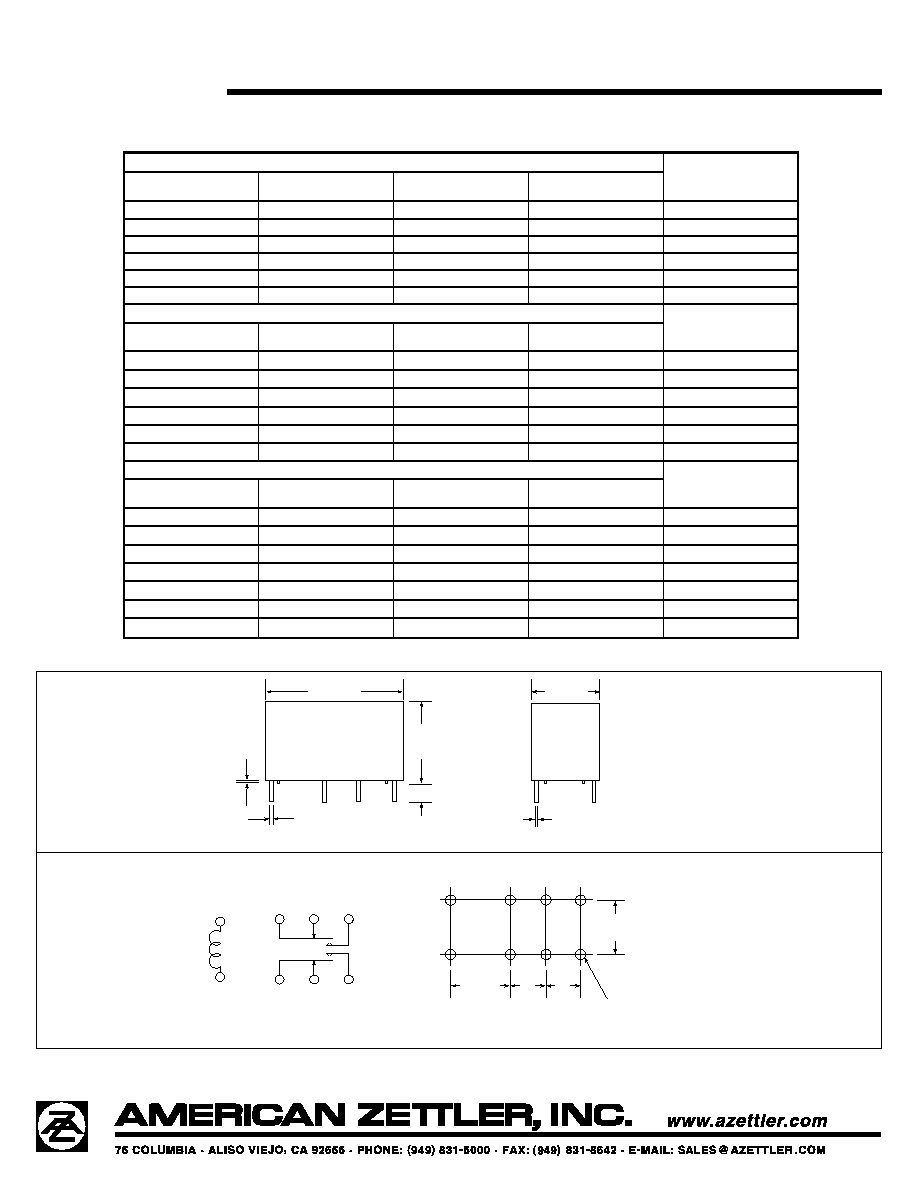
MECHANICAL DATA
WIRING DIAGRAM
PC BOARD LAYOUT
1
16
.795 Max.
(20.2 Max.)
.010
(0.25)
.028
(0.72)
.472 Max.
(12.0 Max.)
.138
(3.5)
.390 Max.
(9.9 Max.)
.016
(.04)
.200
(5.08)
.200
(5.08)
.300
(7.62 )
.300
(7.62)
.0.39 DIA
(0.8)
8 HOLES
Viewed toward terminals
Viewed toward terminals
4
13
11
9
6
8
Dimensions in inches with metric equivalents in parentheses. Tolerance: ± .010"