CONTACTS
Arrangement
DPDT (2 Form C)
Bifurcated crossbar contacts
Ratings
Resistive load:
Max. switched power: 60 W or 62.5 VA
Max. switched current: 2.0 A
Max. switched voltage: 220 VDC or 250 VAC
Rated Load
0.25 A at 240 VAC
UL/CSA
0.5 A at 120 VAC
1.0 A at 30 VDC
0.3 A at 110 VDC
Material
Silver nickel gold plated
Silver palladium available upon request
GENERAL DATA
Life Expectancy
Minimum operations
Mechanical
1 x 10
8
Electrical
1 x 10
5
at 0.5 A, 125 VAC, resistive
2 x 10
5
at 1.0 A, 30 VDC, resistive
Operate Time (set)
3 ms at nominal coil voltage
(typical)
Release Time (reset)
3 ms at nominal coil voltage
(typical)
(with no coil suppression)
Bounce (typical)
At 10 mA contact current
1 ms at operate or release
Dielectric Strength
See table
(at sea level)
Insulation Resistance
10
9
ohms min. at 25∞C, 500 VDC,
50% RH
Ambient Temperature
At nominal coil voltage
Operating
-40∞C (-40∞F) to 85∞C (185∞F)
Storage
-40∞C (-40∞F) to 110∞C (230∞F)
Vibration
Operational, 35 g, 10≠1000 Hz
Shock
Operational, 50 g min., 11 ms
Non-destructive, 150 g min., 11 ms
Max. Solder Temp.
See soldering profile
Temp./Time
Max. Solvent Temp.
80∞C (176∞F)
Max. Immersion Time
30 seconds
Weight
2.5 grams
Enclosure
P.B.T. polyester
Terminals
Tinned copper alloy, P.C.
AZ
8/27/01W
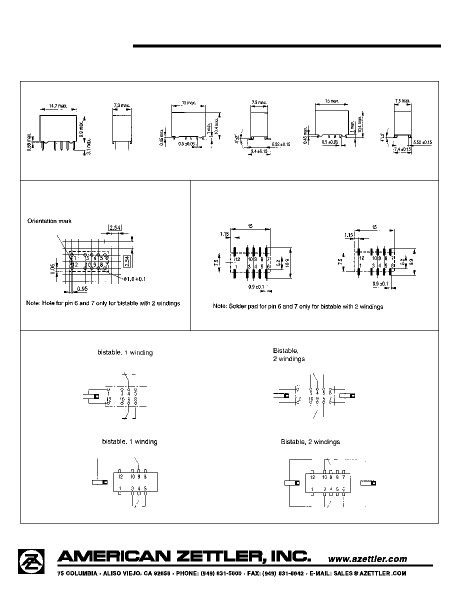
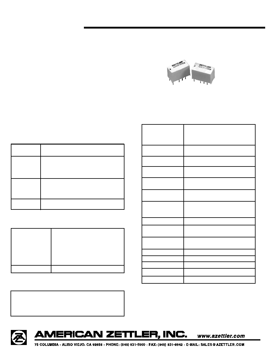
AZ833P
MICROMINIATURE
POLARIZED LATCHING RELAY
FEATURES
∑ Single and dual coil latching versions
∑ High dielectric and surge voltage:
2.5 KV surge (per Bellcore TA≠NWT≠001089)
1.5 KV surge (per FCC Part 68)
1,000 Vrms, open contacts
∑ Low power consumption: 79 mW pickup
∑ Stable contact resistance for low level signal switching
∑ Epoxy sealed for automatic wave soldering and cleaning
∑ UL file E43203; CSA file 702030
∑ All plastics meet UL94 V≠O, 30 min. oxygen index
COIL (Polarized)
Power
At Pickup Voltage
79 mW (dual coil
(typical)
39 mW (single coil)
Max. Continuous
1.0 W at 20∞C (68∞F)
Dissipation
0.78 W at 40∞C (104∞F)
Temperature Rise
At nominal coil voltage
18∞C (32∞F)
Temperature
Max. 110∞C (230∞F)
NOTES
1. All values at 20∞C (68∞F).
2. Relay may pull in with less than "Must Operate" value.
3. Relay has fixed coil polarity.
4. Specifications subject to change without notice.
STANDARD RELAYS: Bistable, 1 coil
Order Number
Nominal Coil
Max. Continuous
Coil Resistance
Must Operate
THT
SMT
SMT
VDC
VDC
± 10%
VDC
Through Hole
Long
Short
3
6.5
128
2.25
AZ833P1≠3DE
AZ833P1S1≠3DE
AZ833P1S2≠3DE
4.5
9.8
289
3.38
AZ833P1≠4.5DE
AZ833P1S1≠4.5DE
AZ833P1S2≠4.5DE
5
10.9
357
3.75
AZ833P1≠5DE
AZ833P1S1≠5DE
AZ833P1S2≠5DE
6
13.0
514
4.50
AZ833P1≠6DE
AZ833P1S1≠6DE
AZ833P1S2≠6DE
9
19.6
1157
6.75
AZ833P1≠9DE
AZ833P1S1≠9DE
AZ833P1S2≠9DE
12
26.2
2057
9.00
AZ833P1≠12DE
AZ833P1S1≠12DE
AZ833P1S2≠12DE
24
52.3
8228
18.00
AZ833P1≠24DE
AZ833P1S1≠24DE
AZ833P1S2≠24DE
RELAY ORDERING DATA
COIL SPECIFICATIONS
STANDARD RELAYS: Bistable, 2 coils
Order Number
Nominal Coil
Max. Continuous
Coil Resistance
Must Operate
THT
SMT
SMT
VDC
VDC
± 10%
VDC
Through Hole
Long
Short
3
6.5
64.3
2.25
AZ833P2≠3DE
AZ833P2S1≠3DE
AZ833P2S2≠3DE
4.5
9.8
145
3.38
AZ833P2≠4.5DE
AZ833P2S1≠4.5DE
AZ833P2S2≠4.5DE
5
10.9
178
3.75
AZ833P2≠5DE
AZ833P2S1≠5DE
AZ833P2S2≠5DE
6
13.0
257
4.50
AZ833P2≠6DE
AZ833P2S1≠6DE
AZ833P2S2≠6DE
9
19.6
578
6.75
AZ833P2≠9DE
AZ833P2S1≠9DE
AZ833P2S2≠9DE
12
26.2
1,029
9.00
AZ833P2≠12DE
AZ833P2S1≠12DE
AZ833P2S2≠12DE
24
52.3
4114
18.00
AZ833P2≠24DE
AZ833P2S1≠24DE
AZ833P2S2≠24DE
AZ
8/27/01W
AZ833P
INITIAL DIELECTRIC STRENGTH (minimum)
SURGE
VRMS, 1 min.
Peak (V)
Rise Time (µS)
Decay Time* (9µS) (1/2 peak)
Between open contacts
1,000
1,500
10
160
Between contact sets
1,000
1,500
2
160
Between coil and contacts
1,800
2,500
2
10
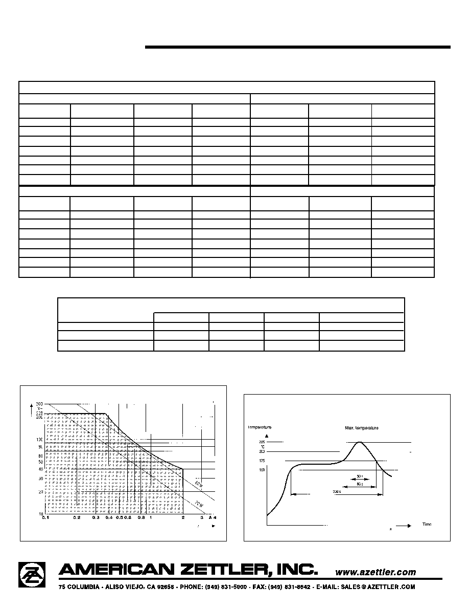
LOAD LIMIT CURVE
* Decay time measured from beginning of surge.
RECOMMENDED SOLDERING PROFILE
(Convection Soldering)
V