
GENERAL DATA
Life Expectancy
Minimum operations
Mechanical
1 x 10
8
at 3Hz
Electrical
1 x 10
5
at 0.5 A, 125 VAC, Res.
2 x 10
5
at 1.0 A, 30 VDC, Res.
Operate Time
2 ms at nominal coil voltage
(typical)
Release Time (typical)
1 ms at nominal coil voltage
(with no coil suppression)
Bounce (typical)
At 10 mA contact current
1 ms at operate or release
Capacitance
< 1 pF at 10 KHz--open contacts
< 1 pF at 10 KHz--adjacent contact sets
Dielectric Strength
See table
(at sea level)
Dropout
Greater than 10% of nominal coil voltage
Insulation Resistance
10
9
ohms min. at 25∞C, 500 VDC,
50% RH
Ambient Temperature
At nominal coil voltage
Operating
-40∞C (-40∞F) to 95∞C (203∞F) (3≠12 VDC)
Storage
-40∞C (-40∞F) to 90∞C (194∞F) (24 VDC)
-40∞C (-40∞F) to 115∞C (239∞F)
Vibration
Operational, 20 g, 10≠55 Hz
Non-destructive, 30 g, 10≠55 Hz
Shock
Operational, 50 g min., 11 ms
Non-destructive, 100 g min., 11 ms
Max. Solder Temp.
350∞C (662∞F) for 3 seconds
Temp./Time
260∞C (500∞F) for 10 seconds
Max. Solvent Temp.
80∞C (176∞F)
Max. Immersion Time
30 seconds
Weight
1.8 grams
Enclosure
P.B.T. polyester
Terminals
Tinned copper alloy, P.C.
AZ
3/14/01W
AZ846
MICROMINIATURE
POLARIZED RELAY
FEATURES
∑ Microminiature size: up to 50% less board area than
previous generation telecom relays
∑ High dielectric and surge voltage:
2.5 KV surge (per Bellcore TA≠NWT≠001089)
1.5 KV surge (per FCC Part 68)
1,000 Vrms, open contacts
∑ Low power consumption: 79 mW pickup
∑ Stable contact resistance for low level signal switching
∑ Epoxy sealed for automatic wave soldering and cleaning
∑ UL file E43203; CSA file 700339
∑ All plastics meet UL94 V≠O, 30 min. oxygen index
CONTACTS
Arrangement
DPDT (2 Form C)
Bifurcated crossbar contacts
Ratings
Resistive load:
Max. switched power: 60 W or 62.5 VA
Max. switched current: 2.0 A
Max. switched voltage: 220 VDC or 250 VAC
Rated Load
UL/CSA
0.5 A at 125 VAC
2.0 A at
30 VDC
0.3 A at 110 VDC
Material
Silver alloy; gold clad
Resistance
< 100 milliohms initially at 6 V, 1 A
COIL (Polarized)
Power
At Pickup Voltage
79 mW (3≠12 VDC)
(typical)
113 mW (24 VDC)
Max. Continuous
1.0 W at 20∞C (68∞F)
Dissipation
0.78 W at 40∞C (104∞F)
Temperature Rise
At nominal coil voltage
18∞C (32∞F) (3≠12 VDC)
25∞C (45∞F) (24 VDC)
Temperature
Max. 115∞C (239∞F)
NOTES
1. All values at 20∞C (68∞F).
2. Relay may pull in with less than "Must Operate" value.
3. Relay has fixed coil polarity.
4. Specifications subject to change without notice.
RELAY ORDERING DATA
STANDARD RELAYS
Nominal Coil
Max. Continuous
Coil Resistance
Must Operate
ORDER NUMBER
VDC
VDC
± 10%
VDC
3
6.9
64
2.25
AZ846≠3
4.5
10.4
145
3.38
AZ846≠4
5
11.5
178
3.75
AZ846≠5
6
13.8
257
4.5
AZ846≠6
9
20.8
579
6.75
AZ846≠9
12
27.7
1,028
9.0
AZ846≠12
24
46.3
2,880
18.0
AZ846≠24
AZ
3/14/01W
AZ846
INITIAL DIELECTRIC STRENGTH (minimum)
SURGE
VRMS, 1 min.
Peak (V)
Rise Time (µS)
Decay Time* (9µS) (1/2 peak)
Between open contacts
1,000
1,500
10
160
Between contact sets
1,000
1,500
2
160
Between coil and contacts
1,800
2,500
2
10
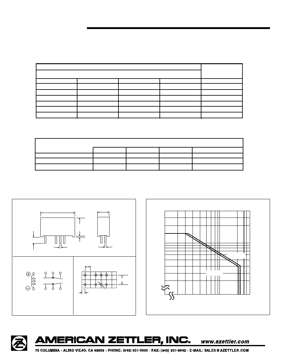
Mechanical Data
Maximum Switching Capacity
* Decay time measured from beginning of surge.
Dimensions in inches with metric equivalents in parentheses. Tolerance: ±0.010"
.366
(9.2)
.579 (14.7)
.291
(7.4)
.010 (0.26)
.016
(0.4)
.020 (0.5)
.126 ± .016
(3.2)
.100
(2.54)
.200
(5.08)
.041 (1.05)
8-ÿ.039
(8-ÿ1.0)
3
4
5
10
9
8
1
12
WIRING DIAGRAM
PC BOARD LAYOUT
Viewed toward terminals
Viewed toward terminals
DC RESISTIVE
LOAD
AC RESISTIVE
LOAD
200
100
0
0.1
0.3
0.5
1.0
2.0
30
Contact Voltage
Cont. Current