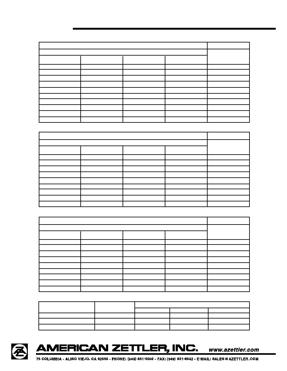
GENERAL DATA
Life Expectancy
Minimum operations
Mechanical
1 x 10
8
operations at 3 Hz
Electrical
2 x 10
5
operations at 0.5 A,
125 VAC, resistive
5 x 10
5
operations at 1.0 A,
30 VDC, resistive
Operate Time (typical)
2 ms at nominal coil voltage
Release Time (typical)
1 ms at nominal coil voltage
(with no coil suppression)
Bounce (typical)
1 ms (at nominal coil voltage)
Capacitance
< 0.5 pF open and adjacent contacts
< 1.0 pF contact to coil
Dielectric Strength
See table
(at sea level)
Insulation Resistance
10
9
ohms min. at 500 VDC
Dropout
Greater than 10% of nominal coil voltage
Ambient Temperature
At nominal coil voltage
Operating
-40∞C (-40∞F) to 85∞C (185∞F)
Storage
-40∞C (-40∞F) to 85∞C (185∞F)
Vibration
Operational, 3.3 mm DA, 10 - 55 Hz
Non-Destructive, 5.5 mm DA, 10 -55 Hz
Shock
Operational, 50g min., 11 ms
Non-Destructive, 100 g min., 6 ms
Enclosure
LCP
Terminals
Tinned copper alloy, P.C.
Max. Solder Temp.
See charts
Max. Solder Time
See charts
Max. Solvent Temp.
80∞C (176∞F)
Max. Immersion Time
30 seconds
Weight
1.5 grams
COIL
Power
At Pickup Voltage
AZ848: 79 mW to 169 mW
(typical)
AZ848P1: 57 mW to 85 mW
AZ848P2: 110 mW to 170 mW
Max. Continuous
826 mW at 20∞C (68∞F) ambient
Dissipation
652 mW at 40∞C (104∞F) ambient
Temperature Rise
At nominal coil voltage
18∞C (32∞F) (3 - 12 VDC coils)
25∞C (45∞F) (18, 24 VDC coils)
34∞C (61∞F) (48 VDC coils)
Temperature
Max. 115∞C (239∞F)
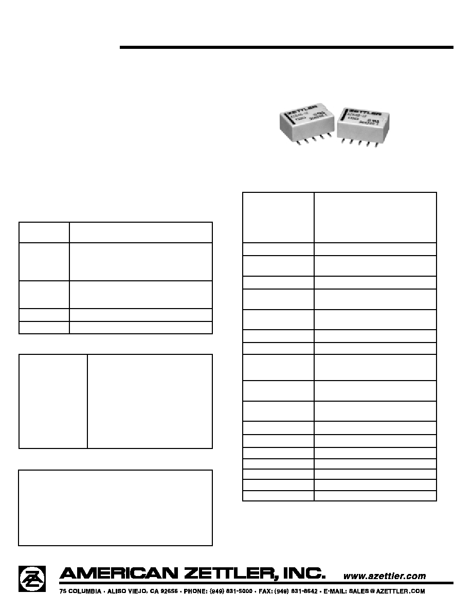
AZ848
11/3/99W
MICROMINIATURE SURFACE
MOUNT POLARIZED RELAY
FEATURES
∑ High dielectric and surge voltage: 1.5 kV surge
(per FCC Part 68) 750 VRMS open contacts
∑ Low power consumption: 56 mW set
∑ Non-latching and latching versions
∑ Single coil and dual coil versions
∑ Stable contact resistance for low level signal switching
∑ Epoxy sealed for automatic wave soldering and cleaning
∑ UL file E43203, CSA 73363
∑ All plastics meet UL94 V-0, 30 min. oxygen index
CONTACTS
Arrangement
DPDT (2 Form C)
Bifurcated crossbar contacts
Ratings
Non-inductive load:
Max. switched power: 60 W or 62.5 VA
Max. switched current: 2 A
Max. switched voltage: 220 VDC or 250 VAC
Rated Load
0.5 A at 125 VAC res.
UL/CSA
2.0 A at 30 VDC res.
0.3 A at 110 VDC res.
Material
Silver palladium; gold clad
Resistance
< 50 milliohms initially at 6 V, 0.1 A
NOTES
1. All values at 20∞C (68∞F).
2. Relay has fixed coil polarity.
3. Relay may pull in with less than "Must Operate" value.
4. Relay adjustment may be affected if undue pressure is exerted
on relay case.
5. For complete isolation between the relay's magnetic fields, it is
recommended that a .197" (5.0 mm) space be provided between
adjacent relays.
6. Specifications subject to change without notice.
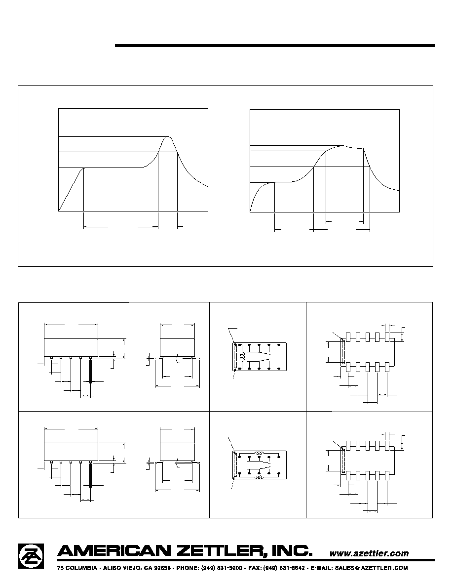
MECHANICAL DATA
[6.62]
.261
[2.94]
10 X .116
[1.0]
10 X .040
[2.54]
.100
[2.54]
.100
[2.54]
.100
[1.92]
.076
[2.54]
.100
[14.0]
.551
[9.0]
.354
[7.62]
.300
[11.5]
.453
[0.2]
.008
[6.5]
.256
[1.92]
.076
[2.54]
.100
[2.54]
.100
[2.54]
.100
[0.75]
.030
[0.5]
.020 TYP
[2.54]
.100
VIEWED TOWARDS TERMINALS
PC BOARD LAYOUT
WIRING DIAGRAMS
VIEWED TOWARDS TERMINALS
ORIENTATION MARK
3∞
7
DEENERGIZED OR RESET CONDITION
(-)
(+)
TYP
10
9
8
1
2
3
4
6
5
[1.0]
10 X .040
[2.94]
10 X .116
[6.62]
.261
[2.54]
.100
[2.54]
.100
[2.54]
.100
[2.54]
.100
[1.92]
.076
[7.62]
.300
[11.5]
.453
[0.2]
.008
[6.5]
.256
[1.92]
.076
[2.54]
.100
[2.54]
.100
[2.54]
.100
[0.75]
.030
[2.54]
.100
[0.5]
.020 TYP
[9.0]
.354
[14.0]
.551
WIRING DIAGRAMS
VIEWED TOWARDS TERMINALS
PC BOARD LAYOUT
VIEWED TOWARDS TERMINALS
ORIENTATION MARK
3∞
TYP
(+)
8
9
10
RESET CONDITION
(+)
3
2
1
5
4
(-)
(-)
6
7
SET
COIL
RESET
COIL
Stripe on top of relay indicates location of pins 1 and 10.
Stripe on top of relay indicates location of pins 1 and 10.
Stripe on top of relay
indicates location of
pins 1 and 10.
Stripe on top of relay
indicates location of
pins 1 and 10.
AZ848
11/3/99W
SOLDERING DATA
3
1
T
TEMPERATURE (
∞
C)
2
T
PREHEATING
SOLDERING
IRS (Infrared Reflow Soldering)
COOLING
T
MAX
30 SEC
120 SEC MAX
3
T
T2
T 1
TEMPERATURE (
∞
C)
PREHEATING
215∞ C MAX
SOLDERING
VPS (Vapor Phase Soldering)
COOLING
60 SEC MAX
90 SEC MAX
60 SEC MAX
T
3= 245∞C MAX
T
2= 200∞C MAX
T
1= 165∞C MAX
T
3= 200∞C MAX
T
2= 165∞C MAX
T
1= 100∞C MAX
Dimensions in inches with metric equivalents in parentheses. Tolerance: ±0.010"