GENERAL DATA
Life Expectancy
Minimum operations
Mechanical
1 x 10
7
Electrical
1 x 10
5
at 10 A 120 VAC Res.
Operate Time (typical)
10 ms at nominal coil voltage
Release Time (typical)
2 ms at nominal coil voltage
(with no coil suppression)
Dielectric Strength
1500 Vrms coil to contact
(at sea level for 1 min.) 1000 Vrms contact to contact
Insulation
1000 megohms min. at 20∞C, 500 VDC,
Resistance
50% RH
Dropout
Greater than 5% of nominal coil voltage
Ambient Temperature
At nominal coil voltage
Operating
-40∞C (-40∞F) to 70∞C (158∞F)
Storage
-40∞C (-42∞F) to 115∞C (239∞F)
Vibration
0.062" DA at 10≠55 Hz
Shock
10 g
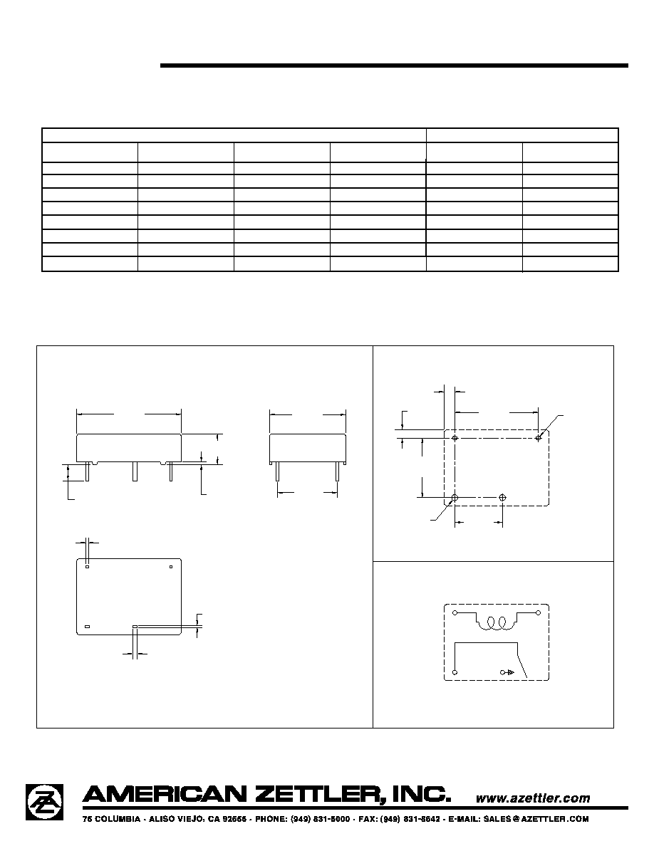
Enclosure
P.B.T. polyester
Terminals
Tinned copper alloy, P.C.
Max. Solder Temp.
270∞C (518∞F)
Max. Solder Time
5 seconds
Max. Solvent Temp.
80∞C (176∞F)
Max. Immersion Time
30 seconds
Weight
5 grams
3/14/01W
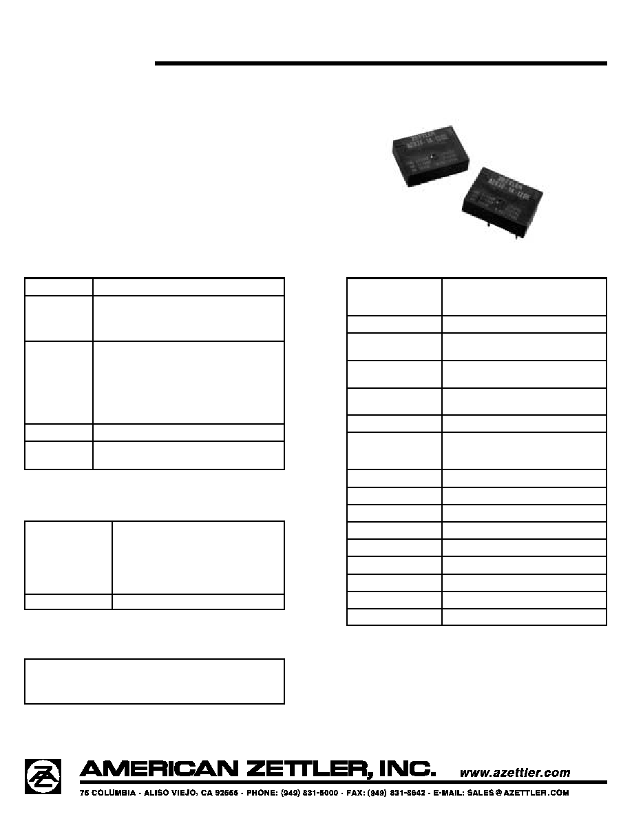
AZ936
10 AMP LOW PROFILE
POWER RELAY
FEATURES
∑ High power switching (2000 VA)
∑ High sensitivity, 190 mW pickup
∑ Low profile (less than .25" height)
∑ SPST (1 Form A)
∑ DC coils up to 100 VDC
∑ UL file E44211, CSA file 702514
∑ TÐV file BL991234205002
CONTACTS
Arrangement
SPST (1 Form A)
Ratings
Resistive load:
Max. switched power: 240 W, 2000 VA
Max. switched current: 10 A
Max. switched voltage: 250 VAC/110 VDC
Rated Load
UL, CSA
10 A at 125 VAC, resistive
8 A at 250/30 VDC, resistive
1
/
10
HP 125 VAC
1
/
10
HP 250 VAC
TÐV
10 A at 125 VAC, resistive
8 A at 250 VAC, 30 VDC, resistive
Material
Silver tin oxide
Resistance
< 100 milliohms initially
(6 V, 1 A voltage drop method)
COIL
Power
At Pickup Voltage
(typical)
190 mW
Max. Continuous
Dissipation
1.2 W at 20∞C (68∞F)
Temperature Rise
20∞C (36∞F) at nominal coil voltage
Temperature
Max. 115∞C (239∞F)
NOTES
1. All values at 20∞C (68∞F).
2. Relay may pull in with less than "Must Operate" value.
3. Specifications subject to change without notice.