GENERAL DATA
Life Expectancy
Minimum operations
Mechanical
1 x 10
9
Electrical
2.5 x 10
5
at 0.4 A, 125 VAC, resistive
3 x 10
6
at 1.0 A, 24 VDC, resistive
Operate Time
1 ms at nominal coil voltage
(typical)
Release Time (typical)
0.4 ms at nominal coil voltage
(with no coil suppression)
Bounce (typical)
At 10 mA contact current
1 ms at operate or release
Dielectric Strength
1500 Vrms contact to coil
(at sea level)
500 Vrms between open contacts
Dropout
Greater than 10% of nominal coil voltage
Insulation Resistance
10
9
ohms min. at 25∞C, 500 VDC,
50% RH
Ambient Temperature
At nominal coil voltage
Operating
-40∞C (-40∞F) to 70∞C (158∞F)
Storage
-40∞C (-40∞F) to 105∞C (221∞F)
Vibration
Operational, 40 g, 10≠200 Hz
Shock
Operational, 50 g min., 11 ms
Non-destructive, 150 g min., 11 ms
Max. Solder Temp.
Vapor phase: 215∞C, 40 Sec.
Temp./Time
Infrared: 215∞C, 40 Sec.
Double wave: 260∞C, 10 Sec.
Max. Solvent Temp.
80∞C (176∞F)
Max. Immersion Time
30 seconds
Weight
1.8 grams
Enclosure
P.B.T. polyester
Terminals
Tinned copper alloy, P.C.
CONTACTS
Arrangement
SPDT (1 Form C)
Bifurcated crossbar contacts
Ratings
Resistive load:
Max. switched power: 30 W or 60 VA
Max. switched current: 1.0 A
Max. switched voltage: 150 VDC or 125 VAC
Rated Load
UL
0.5 A at 120 VAC
1.0 A at
30 VDC
Material
Palladium nickel with gold-rhodium overlay
Resistance
< 50 milliohms initally
(6 V, 10 mA method)
AZ
7/24/02W
AZ956
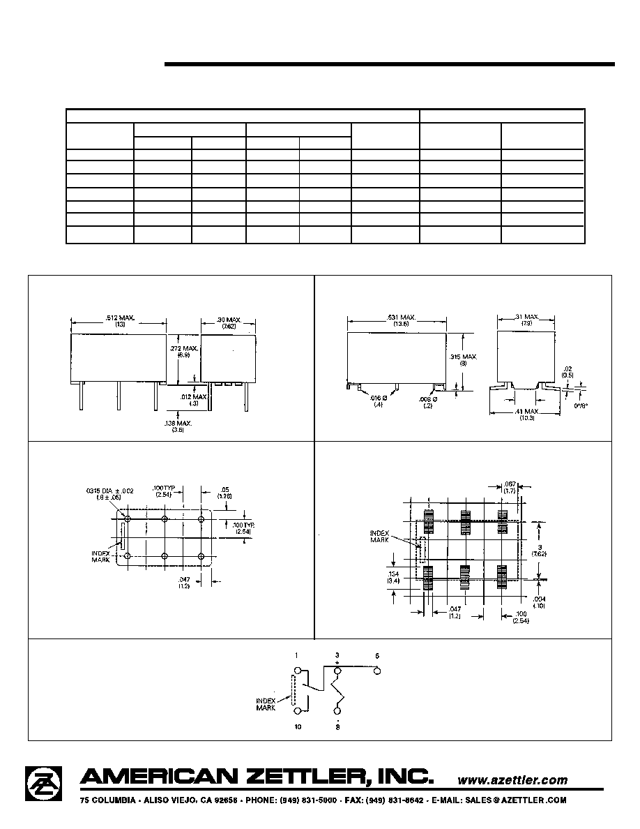
MICROMINIATURE
POLARIZED RELAY
FEATURES
∑ Microminiature size: up to 50% less board area than
previous generation telecom relays
∑ Meets FCC Part 68.302 1500 V lightning surge
∑ Low power consumption: 36 mW pickup
∑ Stable contact resistance for low level signal switching
∑ Epoxy sealed for automatic wave soldering and cleaning
∑ UL, CUR file E43203
∑ All plastics meet UL94 V≠0, 30 min. oxygen index
COIL (Polarized)
Power
At Pickup Voltage
36 mW
(typical)
Max. Continuous
0.5 W at 20∞C (68∞F)
Dissipation
Temperature Rise
At nominal coil voltage
8∞C (15∞F)
Temperature
Max. 105∞C (221∞F)
NOTES
1. All values at 20∞C (68∞F).
2. Relay may pull in with less than "Must Operate" value.
3. Relay has fixed coil polarity.
4. Specifications subject to change without notice.