INPUT
Type
D38 X Z10
D38 X Z15
D38 X Z25
Control Voltage Range
3 to 32 VDC
Turn On Voltage
3 VDC max.
Turn Off Voltage
1 VDC min.
Max. Input Current
35 mA at 32 VDC
Max. Reverse Voltage
-32 VDC
OUTPUT
Operating Voltage Range
36 to 440 Vrms
Blocking Voltage
800 Vpk
Type
D38 X Z10
D38 X Z15
D38 X Z25
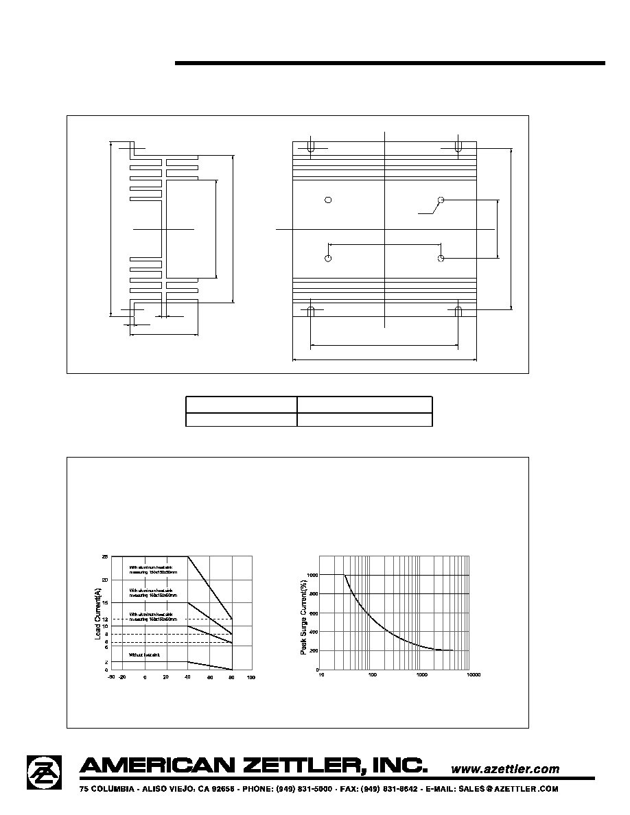
Load Current Range (A)
0.1 to 10
0.1 to 15
0.1 to 25
Max. Surge Current (1/2 Cycle)
100 Apk
150 Apk
250 Apk
Max. Leakage Current
3 mA
5 mA
10 mA
Voltage On-state Drop (max.)
1.5 Vrms
Max. Turn-on Time
1
/
2
cycle plus 1 ms
Max. Turn-off Time
1
/
2
cycle plus 1 ms
Min. Off-state Dv/Dt at Maximum Rated Voltage
200 V/us
Min. Power Factor Allowable
0.5
GENERAL
Dielectric Strength
4000 Vrms min. (at 50/60 Hz, 1 min.)
Insulation Resistance
1000 megohms min. (at 500 VDC)
Max. Capacitance (in/out)
8 pf
Ambient Temperature
Operating: -30∞C (-22∞F) to 80∞C (176∞F)
Storage: -30∞C (-22∞F) to 100∞C (212∞F)
Mounting
Panel Mount
Termination
Screw
Weight
315 g
SG-24F
2/7/03W
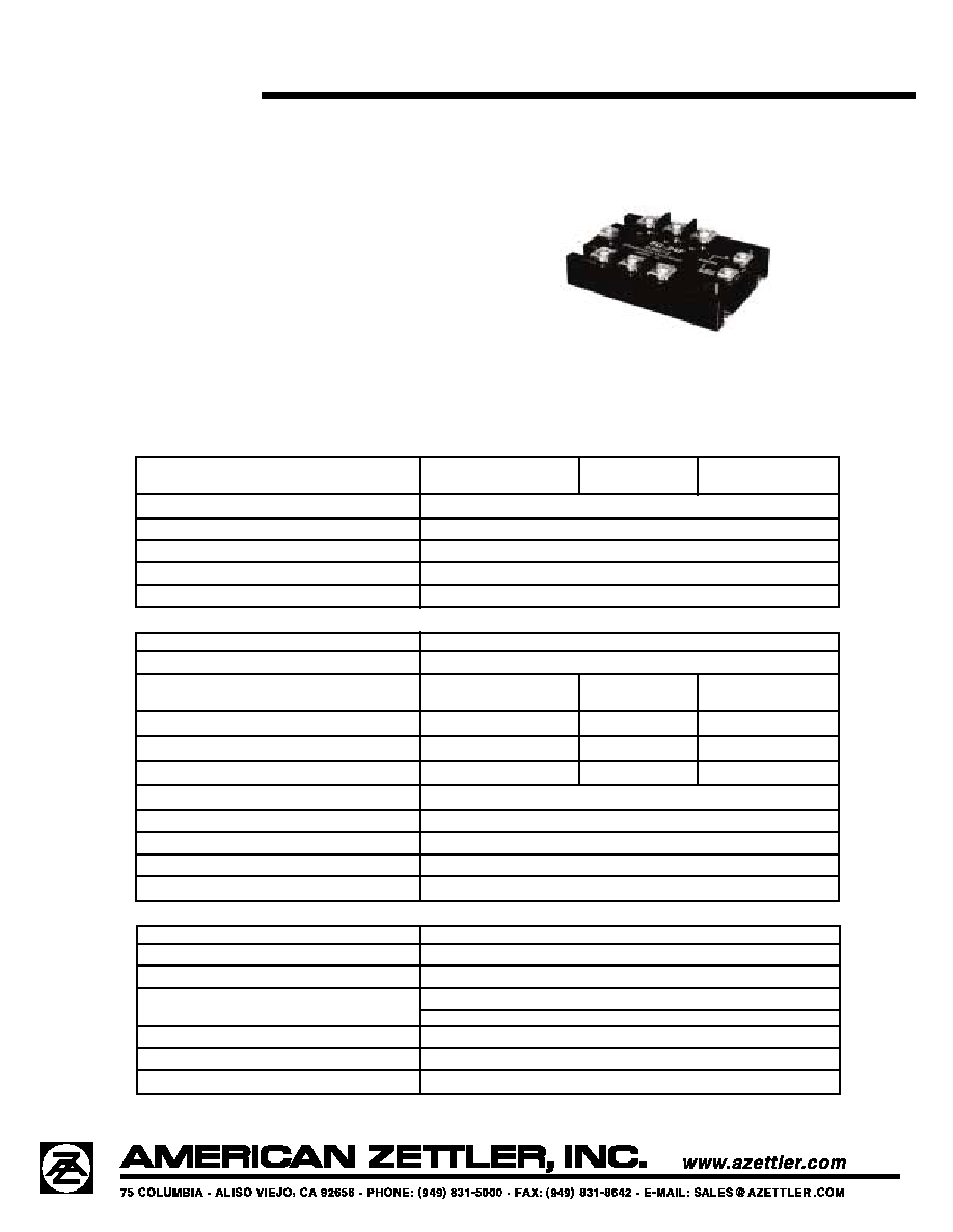
THREE PHASE SOLID STATE RELAY
10 THRU 25 AMPS
36 TO 440 VRMS
FEATURES
∑ Photo isolation
∑ LED status indicator
∑ Up to 800V blocking voltage
∑ Both "Zero Voltage" and phase controllable
"Random" Switching versions
∑ High surge capability
∑ Built-in snubber
∑ Triac Output Circuitry
∑ UL, CUR approval pending
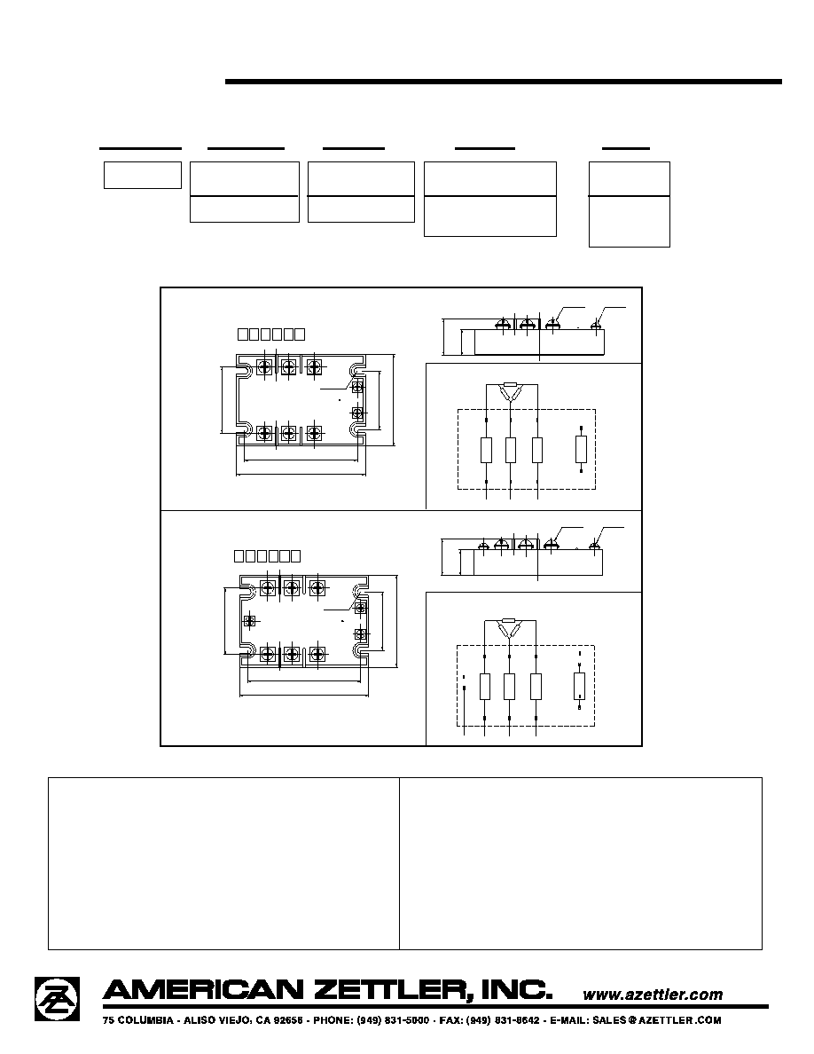
MECHANICAL DATA
INSTALLATION
1.
When mounting the relays side by side, provide a space equiva-
lent to the width of a single SSR between two adjacent SSRs.
Otherwise, reduce the load current flow to 1/2 to 1/3 of the rated
current.
2.
When mounting relays on heat sink surface, first apply a heat
conductive grease to the metal back surface of the SSR. Press
the SSR firmly onto the heat sink to ensure a good seal. Screw
the SSR down to the heat sink.
3.
Next, wire the screw terminals and securely tighten the screws.
PRECAUTIONS
1.
Before connecting a load that generates a high surge current,
such as a lamp load to the SSR, make sure that the SSR can
withstand the surge current of the load.
2.
The product data sheet shows the non-repetitive peak value of
the surge current that flows through the SSR. Normally, use 1/2
of the non-repetitive peak surge current as the standard value. If
a surge current exceeding that value is expected, connect a
quick-blowing fuse to protect the SSR.
2
.
9
53
[
75
]
Max
2.
12
6
[
54
]
1.8
74
[
47.6
]
4.134
[105] Max
3.614
[91.8]
[
]
1.
1
8
1
[
30
]
Max
.8
27
[
21
]
SG-24F/
4-R.104
[R2.65]
Outline Dimensions
6-M4
2-M3
LO
AD
LO
AD
LO
AD
I
NP
U
T
2
.
9
53
[
75
]
2.
12
6
[
54
]
1.8
74
[
47.6
]
INPUT
LO
AD
LO
AD
LO
AD
-
L1
L2
L3
3.614
[91.8]
[
]
4.134
[105] Max
[
]
N
L1
L3
L2
-
+
U
V
W
Wiring Diagram
1.
1
8
1
[
30
]
Max
.8
27
[
21
]
SG-24F/
6-M4
3-M3
4-R.104
[R2.65]
P
U
W
V
+
Wiring Diagram
Outline Dimensions
SG-24F
2/7/03W
RELAY ORDERING DATA
SG-24F
D
38
Z
25
MODEL
INPUT
LOAD
ZERO CROSS
LOAD
VOLTAGE
VOLTAGE
FUNCTION
CURRENT
D: 3VDC TO 32VDC
36 TO 440 VAC
Z: Zero cross turn-on
10: 10 Amp
P: Non-zero cross turn-on
15: 15 Amp
25: 25 Amp
Dimensions in inches with metric equivalents in parentheses. Tolerance: ± .010"