
eZ8 CPU
UM012811-0904
ZiLOG Worldwide Headquarters � 532 Race Street � San Jose, CA 95126-3432
Telephone: 408.558.8500 � Fax: 408.558.8300 �
www.ZiLOG.com
User Manual

UM012811-0904
Discliamer
This publication is subject to replacement by a later edition. To determine whether a later edition exists, or
to request copies of publications, contact:
ZiLOG Worldwide Headquarters
532 Race Street
San Jose, CA 95126-3432
Telephone: 408.558.8500
Fax: 408.558.8300
www.ZiLOG.com
Document Disclaimer
ZiLOG is a registered trademark of ZiLOG Inc. in the United States and in other countries. All other products and/or service
names mentioned herein may be trademarks of the companies with which they are associated.
�2004 by ZiLOG, Inc. All rights reserved. Information in this publication concerning the devices, applications, or technology
described is intended to suggest possible uses and may be superseded. ZiLOG, INC. DOES NOT ASSUME LIABILITY FOR OR
PROVIDE A REPRESENTATION OF ACCURACY OF THE INFORMATION, DEVICES, OR TECHNOLOGY DESCRIBED
IN THIS DOCUMENT. ZiLOG ALSO DOES NOT ASSUME LIABILITY FOR INTELLECTUAL PROPERTY INFRINGE-
MENT RELATED IN ANY MANNER TO USE OF INFORMATION, DEVICES, OR TECHNOLOGY DESCRIBED HEREIN
OR OTHERWISE. Devices sold by ZiLOG, Inc. are covered by warranty and limitation of liability provisions appearing in the
ZiLOG, Inc. Terms and Conditions of Sale. ZiLOG, Inc. makes no warranty of merchantability or fitness for any purpose Except
with the express written approval of ZiLOG, use of information, devices, or technology as critical components of life support sys-
tems is not authorized. No licenses are conveyed, implicitly or otherwise, by this document under any intellectual property rights.

eZ8 CPU
User Manual
UM012811-0904
Table of Contents
iii
Table of Contents
Table of Contents . . . . . . . . . . . . . . . . . . . . . . . . . . . . . . . . . . . . . . . . . . . . . . . . . . . . . . . . . iii
List of Figures . . . . . . . . . . . . . . . . . . . . . . . . . . . . . . . . . . . . . . . . . . . . . . . . . . . . . . . . . . . . . v
List of Tables . . . . . . . . . . . . . . . . . . . . . . . . . . . . . . . . . . . . . . . . . . . . . . . . . . . . . . . . . . . . . .vi
Manual Objectives . . . . . . . . . . . . . . . . . . . . . . . . . . . . . . . . . . . . . . . . . . . . . . . . . . . . . . . . vii
Architectural Overview . . . . . . . . . . . . . . . . . . . . . . . . . . . . . . . . . . . . . . . . . . . . . . . . . . . . . 1
Features . . . . . . . . . . . . . . . . . . . . . . . . . . . . . . . . . . . . . . . . . . . . . . . . . . . . . . . . . . . . . . . 1
Processor Description . . . . . . . . . . . . . . . . . . . . . . . . . . . . . . . . . . . . . . . . . . . . . . . . . . . . 1
Fetch Unit . . . . . . . . . . . . . . . . . . . . . . . . . . . . . . . . . . . . . . . . . . . . . . . . . . . . . . . . . . . . . 2
Instruction State Machine . . . . . . . . . . . . . . . . . . . . . . . . . . . . . . . . . . . . . . . . . . . . . . . . . 2
Program Counter . . . . . . . . . . . . . . . . . . . . . . . . . . . . . . . . . . . . . . . . . . . . . . . . . . . . . . . . 3
eZ8 CPU CONTROL REGISTERS . . . . . . . . . . . . . . . . . . . . . . . . . . . . . . . . . . . . . . . . . 3
Z8 Compatibility . . . . . . . . . . . . . . . . . . . . . . . . . . . . . . . . . . . . . . . . . . . . . . . . . . . . . . . . . . . 9
Overview . . . . . . . . . . . . . . . . . . . . . . . . . . . . . . . . . . . . . . . . . . . . . . . . . . . . . . . . . . . . . . 9
Assembly Language Compatibility . . . . . . . . . . . . . . . . . . . . . . . . . . . . . . . . . . . . . . . . . . 9
New Instructions . . . . . . . . . . . . . . . . . . . . . . . . . . . . . . . . . . . . . . . . . . . . . . . . . . . . . . . . 9
Relocation of the eZ8 CPU Control Registers . . . . . . . . . . . . . . . . . . . . . . . . . . . . . . . . 12
Stack Pointer Compatibility . . . . . . . . . . . . . . . . . . . . . . . . . . . . . . . . . . . . . . . . . . . . . . 12
Reset Compatibility . . . . . . . . . . . . . . . . . . . . . . . . . . . . . . . . . . . . . . . . . . . . . . . . . . . . . 12
Interrupt Compatibility . . . . . . . . . . . . . . . . . . . . . . . . . . . . . . . . . . . . . . . . . . . . . . . . . . 12
Address Space . . . . . . . . . . . . . . . . . . . . . . . . . . . . . . . . . . . . . . . . . . . . . . . . . . . . . . . . . . . . 13
Introduction . . . . . . . . . . . . . . . . . . . . . . . . . . . . . . . . . . . . . . . . . . . . . . . . . . . . . . . . . . . 13
Register File . . . . . . . . . . . . . . . . . . . . . . . . . . . . . . . . . . . . . . . . . . . . . . . . . . . . . . . . . . . 13
Program Memory . . . . . . . . . . . . . . . . . . . . . . . . . . . . . . . . . . . . . . . . . . . . . . . . . . . . . . . 17
Data Memory . . . . . . . . . . . . . . . . . . . . . . . . . . . . . . . . . . . . . . . . . . . . . . . . . . . . . . . . . . 18
Stacks . . . . . . . . . . . . . . . . . . . . . . . . . . . . . . . . . . . . . . . . . . . . . . . . . . . . . . . . . . . . . . . . 18
Addressing Modes . . . . . . . . . . . . . . . . . . . . . . . . . . . . . . . . . . . . . . . . . . . . . . . . . . . . . . . . . 20
Introduction . . . . . . . . . . . . . . . . . . . . . . . . . . . . . . . . . . . . . . . . . . . . . . . . . . . . . . . . . . . 20
Register Addressing (R) . . . . . . . . . . . . . . . . . . . . . . . . . . . . . . . . . . . . . . . . . . . . . . . . . 20
Indirect Register Addressing (IR) . . . . . . . . . . . . . . . . . . . . . . . . . . . . . . . . . . . . . . . . . . 24
Indexed Addressing (X) . . . . . . . . . . . . . . . . . . . . . . . . . . . . . . . . . . . . . . . . . . . . . . . . . 25
Direct Addressing (DA) . . . . . . . . . . . . . . . . . . . . . . . . . . . . . . . . . . . . . . . . . . . . . . . . . 26
Relative Addressing (RA) . . . . . . . . . . . . . . . . . . . . . . . . . . . . . . . . . . . . . . . . . . . . . . . . 27
Immediate Data Addressing (IM) . . . . . . . . . . . . . . . . . . . . . . . . . . . . . . . . . . . . . . . . . . 28

UM012811-0904
Table of Contents
eZ8 CPU
User Manual
iv
Interrupts. . . . . . . . . . . . . . . . . . . . . . . . . . . . . . . . . . . . . . . . . . . . . . . . . . . . . . . . . . . . . . . . 30
Introduction . . . . . . . . . . . . . . . . . . . . . . . . . . . . . . . . . . . . . . . . . . . . . . . . . . . . . . . . . . . 30
Interrupt Enable and Disable . . . . . . . . . . . . . . . . . . . . . . . . . . . . . . . . . . . . . . . . . . . . . . 30
Interrupt Priority . . . . . . . . . . . . . . . . . . . . . . . . . . . . . . . . . . . . . . . . . . . . . . . . . . . . . . . 30
Vectored Interrupt Processing . . . . . . . . . . . . . . . . . . . . . . . . . . . . . . . . . . . . . . . . . . . . . 30
Nesting of Vectored Interrupts . . . . . . . . . . . . . . . . . . . . . . . . . . . . . . . . . . . . . . . . . . . . 32
Polled Interrupt Processing . . . . . . . . . . . . . . . . . . . . . . . . . . . . . . . . . . . . . . . . . . . . . . . 33
Software Interrupt Generation . . . . . . . . . . . . . . . . . . . . . . . . . . . . . . . . . . . . . . . . . . . . . 33
Illegal Instruction Traps. . . . . . . . . . . . . . . . . . . . . . . . . . . . . . . . . . . . . . . . . . . . . . . . . . . . 34
Description . . . . . . . . . . . . . . . . . . . . . . . . . . . . . . . . . . . . . . . . . . . . . . . . . . . . . . . . . . . 34
eZ8 CPU Instruction Set Summary. . . . . . . . . . . . . . . . . . . . . . . . . . . . . . . . . . . . . . . . . . . 35
Assembly Language Programming Introduction . . . . . . . . . . . . . . . . . . . . . . . . . . . . . . . 35
Assembly Language Syntax . . . . . . . . . . . . . . . . . . . . . . . . . . . . . . . . . . . . . . . . . . . . . . 36
eZ8 CPU Instruction Notation . . . . . . . . . . . . . . . . . . . . . . . . . . . . . . . . . . . . . . . . . . . . . 36
eZ8 CPU Instruction Classes . . . . . . . . . . . . . . . . . . . . . . . . . . . . . . . . . . . . . . . . . . . . . . 38
eZ8 CPU Instruction Summary . . . . . . . . . . . . . . . . . . . . . . . . . . . . . . . . . . . . . . . . . . . . 43
eZ8 CPU Instruction Set Description . . . . . . . . . . . . . . . . . . . . . . . . . . . . . . . . . . . . . . . . . 53
Opcode Maps . . . . . . . . . . . . . . . . . . . . . . . . . . . . . . . . . . . . . . . . . . . . . . . . . . . . . . . . . . . . 199
Opcodes Listed Numerically . . . . . . . . . . . . . . . . . . . . . . . . . . . . . . . . . . . . . . . . . . . . . . . 203
Assembly and Object Code Example . . . . . . . . . . . . . . . . . . . . . . . . . . . . . . . . . . . . . . . . 214
Index. . . . . . . . . . . . . . . . . . . . . . . . . . . . . . . . . . . . . . . . . . . . . . . . . . . . . . . . . . . . . . . . . . . 224

eZ8 CPU
User Manual
UM012811-0904
List
of
Figures
v
List of Figures
Figure 1.
eZ8 CPU Block Diagram . . . . . . . . . . . . . . . . . . . . . . . . . . . . . . . . . . . . . . . . 2
Figure 2.
Flags Register . . . . . . . . . . . . . . . . . . . . . . . . . . . . . . . . . . . . . . . . . . . . . . . . 5
Figure 3.
Register File Organization . . . . . . . . . . . . . . . . . . . . . . . . . . . . . . . . . . . . . . 15
Figure 4.
Working Register Addressing Example . . . . . . . . . . . . . . . . . . . . . . . . . . . 16
Figure 5.
16-Bit Register Pair Addressing . . . . . . . . . . . . . . . . . . . . . . . . . . . . . . . . . 17
Figure 6.
Bit Addressing Example . . . . . . . . . . . . . . . . . . . . . . . . . . . . . . . . . . . . . . . 17
Figure 7.
Stack Operations . . . . . . . . . . . . . . . . . . . . . . . . . . . . . . . . . . . . . . . . . . . . . 19
Figure 8.
Register Addressing Using 12-Bit Addresses . . . . . . . . . . . . . . . . . . . . . . . 21
Figure 9.
Register Addressing Using 8-Bit Addresses . . . . . . . . . . . . . . . . . . . . . . . . 22
Figure 10. Register Addressing Using 4-Bit Addresses . . . . . . . . . . . . . . . . . . . . . . . . 23
Figure 11. Indirect Register Addressing to Register File . . . . . . . . . . . . . . . . . . . . . . . 24
Figure 12. Indirect Register Addressing to Program or Data Memory . . . . . . . . . . . . . 25
Figure 13. Indexed Register Addressing . . . . . . . . . . . . . . . . . . . . . . . . . . . . . . . . . . . . 26
Figure 14. Direct Addressing . . . . . . . . . . . . . . . . . . . . . . . . . . . . . . . . . . . . . . . . . . . . 27
Figure 15. Relative Addressing . . . . . . . . . . . . . . . . . . . . . . . . . . . . . . . . . . . . . . . . . . . 28
Figure 16. Immediate Data Addressing . . . . . . . . . . . . . . . . . . . . . . . . . . . . . . . . . . . . . 29
Figure 17. Effects of an Interrupt on the Stack . . . . . . . . . . . . . . . . . . . . . . . . . . . . . . . 31
Figure 18. Interrupt Vectoring in Program Memory Example . . . . . . . . . . . . . . . . . . . 32
Figure 19. Example Instruction Description . . . . . . . . . . . . . . . . . . . . . . . . . . . . . . . . . 53
Figure 20. BTJ Operand Description . . . . . . . . . . . . . . . . . . . . . . . . . . . . . . . . . . . . . . 75
Figure 21. BTJNZ Operand Description . . . . . . . . . . . . . . . . . . . . . . . . . . . . . . . . . . . . 78
Figure 22. BTJZ Operand Description . . . . . . . . . . . . . . . . . . . . . . . . . . . . . . . . . . . . . 81
Figure 23. Opcode Map Cell Description . . . . . . . . . . . . . . . . . . . . . . . . . . . . . . . . . . 199

eZ8 CPU
User Manual
UM012811-0904
List of Tables
vi
List of Tables
Table 1. eZ8 CPU Control Registers . . . . . . . . . . . . . . . . . . . . . . . . . . . . . . . . . . . . . . . . . 4
Table 2. Condition Codes . . . . . . . . . . . . . . . . . . . . . . . . . . . . . . . . . . . . . . . . . . . . . . . . . 7
Table 3. New Function Instructions . . . . . . . . . . . . . . . . . . . . . . . . . . . . . . . . . . . . . . . . . 9
Table 4. New Extended Addressing Instructions . . . . . . . . . . . . . . . . . . . . . . . . . . . . . . 10
Table 5. Instructions with New Opcodes . . . . . . . . . . . . . . . . . . . . . . . . . . . . . . . . . . . . 11
Table 6. eZ8 CPU Control Registers . . . . . . . . . . . . . . . . . . . . . . . . . . . . . . . . . . . . . . . . 14
Table 7. Program Memory Map Example . . . . . . . . . . . . . . . . . . . . . . . . . . . . . . . . . . . . 18
Table 8. Assembly Language Syntax Example 1. . . . . . . . . . . . . . . . . . . . . . . . . . . . . . . 36
Table 9. Assembly Language Syntax Example 2 . . . . . . . . . . . . . . . . . . . . . . . . . . . . . . 36
Table 10. Notational Shorthand . . . . . . . . . . . . . . . . . . . . . . . . . . . . . . . . . . . . . . . . . . . . 37
Table 11. Additional Symbols . . . . . . . . . . . . . . . . . . . . . . . . . . . . . . . . . . . . . . . . . . . . . 38
Table 12. Arithmetic Instructions . . . . . . . . . . . . . . . . . . . . . . . . . . . . . . . . . . . . . . . . . . 39
Table 13. Bit Manipulation Instructions . . . . . . . . . . . . . . . . . . . . . . . . . . . . . . . . . . . . . 39
Table 14. Block Transfer Instructions . . . . . . . . . . . . . . . . . . . . . . . . . . . . . . . . . . . . . . . 40
Table 15. CPU Control Instructions . . . . . . . . . . . . . . . . . . . . . . . . . . . . . . . . . . . . . . . . . 40
Table 16. Logical Instructions . . . . . . . . . . . . . . . . . . . . . . . . . . . . . . . . . . . . . . . . . . . . . 41
Table 17. Load Instructions . . . . . . . . . . . . . . . . . . . . . . . . . . . . . . . . . . . . . . . . . . . . . . . 41
Table 18. Program Control Instructions . . . . . . . . . . . . . . . . . . . . . . . . . . . . . . . . . . . . . 42
Table 19. Rotate and Shift Instructions . . . . . . . . . . . . . . . . . . . . . . . . . . . . . . . . . . . . . . 42
Table 20. eZ8 CPU Instruction Summary . . . . . . . . . . . . . . . . . . . . . . . . . . . . . . . . . . . 43
Table 21. Operation of the DAA Instruction . . . . . . . . . . . . . . . . . . . . . . . . . . . . . . . . . . 99
Table 22. Opcode Map Abbreviations . . . . . . . . . . . . . . . . . . . . . . . . . . . . . . . . . . . . . . 200
Table 23. eZ8 CPU Instructions Sorted by Opcode . . . . . . . . . . . . . . . . . . . . . . . . . . . . 203
Table 24. Assembly and Object Code Example . . . . . . . . . . . . . . . . . . . . . . . . . . . . . . 214

eZ8 CPU
User Manual
UM012811-0904
Manual
Objectives
vii
Manual Objectives
This user manual describes the architecture and instruction set of the eZ8 CPU.
About This Manual
ZiLOG recommends that the user read and understand everything in this manual before
setting up and using the product. However, we recognize that there are different styles of
learning. Therefore, we have designed this manual to be used either as a how to procedural
manual or a reference guide to important data.
Intended Audience
This document is written for ZiLOG customers who are experienced at working with
microprocessors or in writing assembly code or compilers.
Manual Organization
The User Manual is divided into ten sections; each section details a specific topic about
the product.
Architectural Overview
Presents an overview of the eZ8 CPU's features and benefits, and a description of its
architecture.
Z8 Compatibility
Provides information for users who are familiar with programming ZiLOG's classic Z8
�
CPU or who are planning to use existing Z8
�
code with the eZ8 CPU.
Address Space
Describes the three address spaces accessible by the eZ8 CPU - Register File, Program
Memory, and Data Memory.

UM012811-0904
Manual
Objectives
eZ8 CPU
User Manual
viii
Addressing Modes
Details the eZ8 CPU's six addressing modes:
�
Register (R)
�
Indirect Register (IR)
�
Indexed (X)
�
Direct (DA)
�
Relative (RA)
�
Immediate Data (IM)
�
Extended Register (ER)
Interrupts
Describes eZ8 CPU operation in response to interrupt requests from either internal periph-
erals or external devices.
Illegal Instruction Traps
Describes the consequences of executing undefined opcodes.
eZ8 CPU Instruction Set Summary
Lists assembly language instructions, including mnemonic definitions and a summary of
the User Manual instruction set.
Opcode Maps
Presents a detailed diagram of each opcode table.
Opcodes Listed Numerically
Provides an easy reference for locating instructions by their opcode.
Sample Program Listing
A sample program shows how the instructions, using many of the available memory
modes, will translate into object code after assembly.
Manual Conventions
The following assumptions and conventions are adopted to provide clarity and ease of use:
Courier Typeface
Commands, code lines and fragments, bits, equations, hexadecimal addresses, and various
executable items are distinguished from general text by the use of the
Courier
typeface.

UM012811-0904
Manual
Objectives
eZ8 CPU
User Manual
ix
Where the use of the font is not indicated, as in the Index, the name of the entity is pre-
sented in upper case.
�
Example: FLAGS[1] is
smrf
.
Hexadecimal Values
Hexadecimal values are designated by uppercase
H
and appear in the
Courier
typeface.
�
Example: R1 is set to
F8H.
Brackets
The square brackets, [ ], indicate a register or bus.
�
Example: for the register R1[7:0], R1 is an 8-bit register, R1[7] is the most significant
bit, and R1[0] is the least significant bit.
Braces
The curly braces, { }, indicate a single register or bus created by concatenating some com-
bination of smaller registers, buses, or individual bits.
�
Example: the 12-bit register address {
0H
, RP[7:4], R1[3:0]} is composed of a 4-bit
hexadecimal value (
0H
) and two 4-bit register values taken from the Register Pointer
(RP) and Working Register R1.
0H
is the most significant nibble (4-bit value) of the
12-bit register, and R1[3:0] is the least significant nibble of the 12-bit register.
Parentheses
The parentheses, ( ), indicate an indirect register address lookup.
�
Example: (R1) is the memory location referenced by the address contained in the
Working Register R1.
Parentheses/Bracket Combinations
The parentheses, ( ), indicate an indirect register address lookup and the square brackets,
[ ], indicate a register or bus.
�
Example: assume PC[15:0] contains the value
1234h
. (PC[15:0]) then refers to the
contents of the memory location at address
1234h
.
Use of the Words Set, Reset and Clear
The word set implies that a register bit or a condition contains a logical 1. The word reset
or clear implies that a register bit or a condition contains a logical 0. When either of these
terms is followed by a number, the word logical may not be included; however, it is
implied.

UM012811-0904
Manual
Objectives
eZ8 CPU
User Manual
x
Notation for Bits and Similar Registers
A field of bits within a register is designated as: Register[n:n].
�
Example: ADDR[15:0] refers to bits 15 through bit 0 of the Address.
Use of the Terms LSB, MSB, lsb, and msb
In this document, the terms LSB and MSB, when appearing in upper case, mean least sig-
nificant byte and most significant byte, respectively. The lowercase forms, lsb and msb,
mean least significant bit and most significant bit, respectively.
Use of Initial Uppercase Letters
Initial uppercase letters designate settings, modes, and conditions in general text.
�
Example 1: Stop mode.
�
Example 2: The receiver forces the SCL line to Low.
�
The Master can generate a Stop condition to abort the transfer.
Use of All Uppercase Letters
The use of all uppercase letters designates the names of states and commands.
�
Example 1: The bus is considered BUSY after the Start condition.
�
Example 2: A START command triggers the processing of the initialization sequence.
Bit Numbering
Bits are numbered from 0 to n�1 where n indicates the total number of bits. For example,
the 8 bits of a register are numbered from 0 to 7.
Safeguards
It is important that all users understand the following safety terms, which are defined here.
Indicates a procedure or file may become corrupted if the
user does not follow directions.
Trademarks
eZ8 and Z8
�
are trademarks of
ZiLOG, Inc
.
Caution:

eZ8 CPU
User Manual
UM012811-0904
Architectural
Overview
1
Architectural Overview
FEATURES
The eZ8 is ZiLOG's latest 8-bit central processing unit (CPU) designed to meet the con-
tinuing demand for faster and more code-efficient microcontrollers. The eZ8 CPU exe-
cutes a superset of the original Z8
�
instruction set. The features of the eZ8 CPU include:
�
Direct register-to-register architecture allows each register to function as an
accumulator. This improves execution time and decreases the required program
memory.
�
Software stack allows much greater depth in subroutine calls and interrupts than
hardware stacks.
�
Compatible with Z8
�
assembly instruction set.
�
Expanded internal Register File allows access of up to 4KB.
�
New instructions improve execution efficiency for code developed using higher-level
programming languages including C.
�
Pipelined instruction fetch and execution
PROCESSOR DESCRIPTION
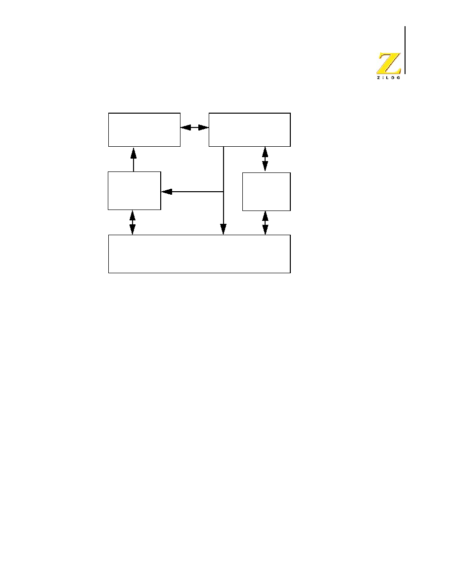
The eZ8 CPU contains two major functional blocks - the Fetch Unit and the Execution
Unit. The Execution Unit is further subdivided into the Instruction State Machine, Pro-
gram Counter, CPU Control Registers, and Arithmetic Logic Unit (ALU). Figure 1 illus-
trates the eZ8 CPU architecture.
UM012811-0904
Architectural
Overview
eZ8 CPU
User Manual
2
Figure 1. eZ8 CPU Block Diagram
FETCH UNIT
The Fetch Unit controls the memory interface. Its primary function is to fetch opcodes and
operands from memory. The Fetch Unit also fetches interrupt vectors or reads and writes
memory in the Program or Data Memory.
The Fetch Unit performs a partial decoding of the opcode to determine the number of
bytes to fetch for the operation. The Fetch Unit operation sequence follows:
1. Fetch the opcode
2. Determine the operand size (number of bytes)
3. Fetch the operands
4. Present the opcode and operands to the Instruction State Machine.
The Fetch Unit is pipelined and operates semi-independently from the rest of the eZ8
CPU.
INSTRUCTION STATE MACHINE
The Instruction State Machine is the controller for the eZ8 CPU Execution Unit. After the
initial operation decode by the Fetch Unit, the Instruction State Machine takes over and
completes the instruction. The Instruction State Machine performs register read and write
operations and generates addresses.
Fetch Unit
Instruction
State Machine
CPU Control
Registers
Program
Counter
Arithmetic Logic Unit

UM012811-0904
Architectural
Overview
eZ8 CPU
User Manual
3
Instruction Cycle Time
The instruction cycle times vary from instruction to instruction, allowing higher perfor-
mance given a specific clock speed. Minimum instruction execution time for standard
CPU instructions is two clock cycles (only the BRK instruction executes in a single cycle).
Because of the variation in the number of bytes required for different instructions, delay
cycles can occur between instructions. Delay cycles are added any time the number of
bytes in the next instruction exceeds the number of clock cycles the current instruction
takes to execute. For example, if the eZ8 CPU executes a 2-cycle instruction while fetch-
ing a 3-byte instruction, a delay cycle occurs because the Fetch Unit has only two cycles to
fetch the three bytes. The Execution Unit is idle during a delay cycle.
PROGRAM COUNTER
The Program Counter contains a 16-bit counter and a 16-bit adder. The Program Counter
monitors the address of the current memory address and calculates the next memory
address. The Program Counter increments automatically according to the number of bytes
fetched by the Fetch Unit. The 16-bit adder increments and handles Program Counter
jumps for relative addressing.
eZ8 CPU CONTROL REGISTERS
The eZ8 CPU contains four CPU control registers that are mapped into the Register File
address space. These four eZ8 CPU control registers are:
�
Stack Pointer High Byte
�
Stack Pointer Low Byte
�
Register Pointer
�
Flags
The eZ8 CPU register bus can access up to 4K (4096) bytes of register space. In all eZ8
CPU products, the upper 256 bytes are reserved for control of the eZ8 CPU, the on-chip
peripherals, and the I/O ports. The eZ8 CPU control registers are always located at
addresses from
FFCH
to
FFFH
as listed in Table 1 on page 4.

UM012811-0904
Architectural
Overview
eZ8 CPU
User Manual
4
Stack Pointer Registers
The eZ8 CPU allows the user to relocate the stack within the Register File. The stack can
be located at addresses from
000H
to
EFFH
. The 12-bit Stack Pointer value is given by
{SPH[3:0], SPL[7:0]}. The Stack Pointer has a 12-bit increment/decrement capability for
stack operations, allowing the Stack Pointer to operate over more than one page (256-byte
boundary) of the Register File. The Stack Pointer register values are undefined after Reset.
Register Pointer
The Register Pointer contains address information for the current Working Register Group
and the Register File Page. The Page Pointer is the lower 4-bits of the Register Pointer,
RP[3:0], and points to the current Page. There are sixteen 256-byte Pages available. The
Working Register Group Pointer is the upper 4 bits of the Register Pointer, RP[7:4], and
points to one of sixteen 16-byte Working Register Groups. There are 16 Working Register
Groups per page. For more information on the Register File, please refer to the sec-
tion`'Address Space" on page 13.
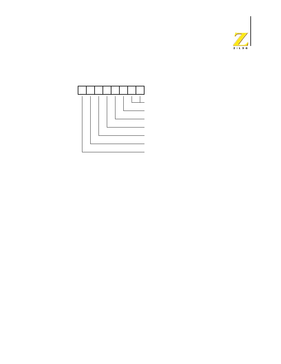
Flags Register
The Flags Register contains the status information regarding the most recent arithmetic,
logical, bit manipulation or rotate and shift operation. The Flags Register contains six bits
of status information that are set or cleared by CPU operations. Four of the bits (C, V, Z
and S) can be tested with conditional jump instructions. Two flags (H and D) cannot be
tested and are used for Binary-Coded Decimal (BCD) arithmetic.
The two remaining bits, User Flags (F1 and F2), are available as general-purpose status
bits. User Flags are unaffected by arithmetic operations and must be set or cleared by
instructions. The User Flags cannot be used with conditional Jumps. They are undefined at
initial power-up and are unaffected by Reset. Figure 2 illustrates the flags and their bit
positions in the Flags Register.
Table 1. eZ8 CPU Control Registers
Register
Mnemonic
Register Description
Address
(Hex)
FLAGS
Flags
FFC
RP
Register Pointer
FFD
SPH
Stack Pointer High Byte
FFE
SPL
Stack Pointer Low Byte
FFF
UM012811-0904
Architectural
Overview
eZ8 CPU
User Manual
5
Figure 2. Flags Register
Interrupts, the Software Trap (TRAP) instruction, and Illegal Instruction Traps all write
the value of the Flags Register to the stack. Executing an Interrupt Return (IRET) instruc-
tion restores the value saved on the stack into the Flags Register.
Carry Flag
The Carry flag (C) is 1 when the result of an arithmetic operation generates a carry out of
or a borrow into the most significant bit (Bit 7) of the data. Otherwise, the Carry flag is 0.
Some bit rotate or shift instructions also affect the Carry flag. There are three instructions
available for directly changing the value of the Carry Flag:
�
Complement Carry Flag (CCF)
�
Reset Carry Flag (RCF)
�
Set Carry Flag (SCF)
Zero Flag
For arithmetic and logical operations, the Zero (Z) flag is 1 if the result is 0. Otherwise, the
Zero flag is 0. If the result of testing bits in a register is
00H
, the Zero flag is 1; otherwise,
the Zero flag is 0. Also, if the result of a rotate or shift operation is
00H
, the Zero flag is 1;
otherwise, the Zero flag is 0.
Sign Flag
The Sign (S) flag stores the value of the most-significant bit of a result following an arith-
metic, logical, rotate or shift operation. For signed numbers, the eZ8 CPU uses binary
two's complement to represent the data and perform the arithmetic operations. A 0 in the
C Z S V D H F2 F1 Flags Register
Bit
0
Bit
7
Half Carry Flag
Decimal Adjust Flag
Overflow Flag
Sign Flag
Zero Flag
Carry Flag
User Flags

UM012811-0904
Architectural
Overview
eZ8 CPU
User Manual
6
most significant bit position (Bit 7) identifies a positive number; therefore, the Sign flag is
also 0. A 1 in the most significant position (Bit 7) identifies a negative number; therefore,
the Sign flag is also 1.
Overflow Flag
For signed arithmetic, rotate or shift operations, the Overflow (V) flag is 1 when the result
is greater than the maximum possible number (>127) or less than the minimum possible
number (<�128) that can be represented with 8-bits in two's complement form. The Over-
flow flag is 0 if no overflow occurs. Following logical operations, the Overflow flag is 0.
Following addition operations, the Overflow flag is 1 when the operands have the same
sign, but the result has the opposite sign. Following subtraction operations, the Overflow
flag is 1 if the two operands are of opposite sign and the sign of the result is same as the
sign of the source. Following rotation operations, the Overflow flag is 1 if the sign bit of
the destination operand changed during rotation.
Decimal Adjust Flag
The Decimal Adjust (D) flag is used for Binary-Coded Decimal (BCD) arithmetic opera-
tions. Because the algorithm for correcting BCD operations is different for addition and
subtraction, this flag specifies the type of instruction that was last executed, enabling the
subsequent decimal adjust (DA) operation. Normally, the Decimal Adjust flag cannot be
used as a test condition. After a subtraction, the Decimal Adjust flag is 1. Following an
addition, it is 0.
Half Carry Flag
The Half Carry (H) flag is 1 when an addition generates a carry from Bit 3 or a subtraction
generates a borrow from Bit 4. The DA instruction converts the binary result of a previous
addition or subtraction into the correct BCD result using the Half Carry flag. As in the
case of the Decimal Adjust flag, the user does not normally access this flag directly.
Condition Codes
The C, Z, S and V flags control the operation of the conditional jump (JP cc and JR cc)
instructions. Sixteen frequently useful functions of the flag settings are encoded in a 4-bit
field called the condition code (cc), which forms Bits 7:4 of the first opcode of conditional
jump instructions. Table 2 summarizes the condition codes. Some binary condition codes
can be created using more than one assembly code mnemonic. The result of the flag test
operation determines if the conditional jump executes.

UM012811-0904
Architectural
Overview
eZ8 CPU
User Manual
7
Arithmetic Logic Unit
The Arithmetic Logic Unit (ALU) performs arithmetic and logical operations on the data.
The arithmetic operations include addition, subtraction, and multiplication. The logical
functions include binary logic operations, bit shifting, and bit rotation.
Byte Ordering
For multi-byte data, the eZ8 CPU stores the most significant byte in the lowest memory
address. For example, the value 1 can be stored as a 2-byte (16-bit) number in Register
Table 2. Condition Codes
Binary
Hex
Assembly
Mnemonic Definition
Flag Test Operation
0000
0
F
Always False
�
0001
1
LT
Less Than
(S XOR V) = 1
0010
2
LE
Less Than or Equal
(Z OR (S XOR V)) = 1
0011
3
ULE
Unsigned Less Than or Equal
(C OR Z) = 1
0100
4
OV
Overflow
V = 1
0101
5
Ml
Minus
S = 1
0110
6
Z
Zero
Z = 1
0110
6
EQ
Equal
Z = 1
0111
7
C
Carry
C = 1
0111
7
ULT
Unsigned Less Than
C = 1
1000
8
T (or blank) Always True
�
1001
9
GE
Greater Than or Equal
(S XOR V) = 0
1010
A
GT
Greater Than
(Z OR (S XOR V)) = 0
1011
B
UGT
Unsigned Greater Than
(C = 0 AND Z = 0)
1100
C
NOV
No Overflow
V = 0
1101
D
PL
Plus
S = 0
1110
E
NZ
Non-Zero
Z = 0
1110
E
NE
Not Equal
Z = 0
1111
F
NC
No Carry
C = 0
1111
F
UGE
Unsigned Greater Than or Equal C = 0

UM012811-0904
Architectural
Overview
eZ8 CPU
User Manual
8
Pair
122H
and
123H
. The value is stored as
0001H
. The most-significant byte (
00H
) is
stored in the lowest memory address at
122H
. The least-significant byte (
01H
) is stored in
the higher memory address at
123H
. This ordering of multi-byte data is often referred to as
"big endian".

eZ8 CPU
User Manual
UM012811-0904
Z8 Compatibility
9
Z8 Compatibility
OVERVIEW
The eZ8 CPU is an extension and improvement of ZiLOG's popular, easy-to-use, and
powerful Z8
�
CPU architecture. Users who have experience programming the Z8
�
CPU
will have no difficulty adapting to the eZ8 CPU. All users will appreciate the new instruc-
tions that improve execution for programs developed in high-level programming lan-
guages such as C.
ASSEMBLY LANGUAGE COMPATIBILITY
The eZ8 CPU executes all Z8
�
assembly language instructions other than WDH (Watch-
Dog Timer Enable During HALT Mode at opcode 4FH). Users with existing Z8
�
assem-
bly code can easily compile their code to use the eZ8 CPU. The assembler for the eZ8
CPU is available for download from
www.zilog.com.
NEW INSTRUCTIONS
The eZ8 CPU features many new instructions to increase processor efficiency and allow
access to the expanded 4KB Register File. There are two classes of new instructions avail-
able in the eZ8 CPU - New Function instructions and Extended Addressing instructions.
New Function Instructions
Table 3 lists the instructions that provide new functionality.
Table 3. New Function Instructions
Mnemonic Instruction Description
ATM
Atomic Execution
BCLR
Bit Clear
BIT
Bit Set or Clear
BRK
Break
BSET
Bit Set
BSWAP
Bit Swap

UM012811-0904
Z8 Compatibility
eZ8 CPU
User Manual
10
Extended Addressing Instructions
New Extended Addressing instructions allow data movement between Register File pages.
These instructions allow the generation of a 12-bit address and direct access to any register
value in the 4KB Register File address space. Table 4. lists the new Extended Addressing
instructions
BTJ
Bit Test and Jump
BTJNZ
Bit Test and Jump if Non-Zero
BTJZ
Bit Test and Jump if Zero
CPC
Compare with Carry
LDC
Load Constant
LDCI
Load Constant and Auto-Increment Addresses
LEA
Load Effective Address
MULT
8-bit X 8-bit multiply with 16-bit result
SRL
Shift Right Logical
TRAP
Software Trap
Table 4. New Extended Addressing Instructions
Mnemonic Instruction Description
ADCX
Add with Carry using Extended Addressing
ADDX
Add using Extended Addressing
ANDX
Logical AND using Extended Addressing
CPCX
Compare with Carry using Extended Addressing
CPX
Compare using Extended Addressing
LDWX
Load Word using Extended Addressing
LDX
Load using Extended Addressing
ORX
Logical OR using Extended Addressing
POPX
Pop using Extended Addressing
PUSHX
Push using Extended Addressing
SBCX
Subtract with Carry using Extended Addressing
SUBX
Subtract using Extended Addressing
Table 3. New Function Instructions (Continued)
Mnemonic Instruction Description

UM012811-0904
Z8 Compatibility
eZ8 CPU
User Manual
11
Alternate Function Opcode
To accommodate the new instructions, the opcode
1FH
refers to a new second opcode
map. The
1FH
is pre-pended to an opcode to select the alternate functions available on the
second opcode map. The CPC, CPCX, SRL, LDWX and PUSH (immediate) instructions
use this second opcode map. Users writing assembly language code can employ the CPC,
CPCX, SRL, LDWX and PUSH (immediate) instructions directly. The eZ8 CPU assem-
bler automatically inserts the
1FH
opcode as necessary.
Moved Instructions
Some of the existing Z8
�
CPU instructions have been moved to new opcodes in the eZ8
CPU. Table 5 lists these moved instruction.
Removed Instructions
The instruction types LD r1, R2 and LD R1, r2 have been removed from the opcode map
as they are now subsets of the LD instruction (opcode E4) using Escaped mode address-
ing. In the Z8
�
CPU, these instructions used opcodes
08H
through
F8H
and
09H
through
F9H
. The assembler for the eZ8 CPU continues to support these instructions. Refer to the
Address Modes chapter and the LD instruction description for more information.
The WDH (Watch-Dog Timer Enable During HALT Mode) instruction has also been
removed. For information regarding the Watch-Dog Timer, refer to the Product Specifica-
tion for the specific device.
TCMX
Test Complement Under Mask using Extended Addressing
TMX
Test Under Mask using Extended Addressing
XORX
Logical XOR using Extended Addressing
Table 5. Instructions with New Opcodes
Instruction
eZ8 CPU Opcode (Hex) Z8
�
CPU Opcode (Hex)
SRP
01
31
DEC R1
30
00
DEC IR1
31
01
JP IRR1
C4
30
NOP
0F
FF
Table 4. New Extended Addressing Instructions (Continued)
Mnemonic Instruction Description

UM012811-0904
Z8 Compatibility
eZ8 CPU
User Manual
12
RELOCATION OF THE EZ8 CPU CONTROL REGISTERS
The four control registers within the eZ8 CPU have new addresses to take advantage of the
larger Register File.
Stack Pointer High and Low Byte Registers
The Stack Pointer Low Byte (SPL) now resides at address
FFFH
in the Register File. The
Stack Pointer High Byte (SPH) now resides at address
FFEH
.
Register Pointer
The Register Pointer (RP) now resides at address
FFDH
in the Register File.
Flags Register
The Flags Register (FLAGS) now resides at address
FFCH
in the Register File.
STACK POINTER COMPATIBILITY
The stack pointer is now 12-bits in length and given by {SPH[3:0], SPL[7:0]}. This
change allows the origin of the stack to be placed at any address from
000H
to
EFFH
where
general-purpose registers are available. Refer to the device-specific Product Specification
for available Register File addresses. All stack pointer operations occur within the Regis-
ter File address space.
RESET COMPATIBILITY
Unlike the Z8
�
CPU which uses a fixed reset address of
00CH
, the eZ8 CPU uses a vec-
tored reset. Program Memory stores the RESET vector at addresses
0002H
and
0003H
(most significant byte at
0002H
and least significant byte at
0003H
). When the eZ8 CPU
is reset it fetches the RESET vector at addresses
0002H
and
0003H.
The eZ8 CPU writes
the RESET factor to the Program Counter. The eZ8 CPU executes code at the new Pro-
gram Counter address.
INTERRUPT COMPATIBILITY
The interrupt table now resides at starting address
0008H
in Program Memory to accom-
modate the increased number of interrupts available with the eZ8 CPU.

eZ8 CPU
User Manual
UM012811-0904
Address
Space
13
Address Space
INTRODUCTION
The eZ8 CPU can access three distinct address spaces:
�
The Register File contains addresses for the general-purpose registers and the eZ8
CPU, peripheral, and I/O port control registers.
�
The Program Memory contains addresses for all memory locations having executable
code and/or data.
�
The Data Memory contains addresses for all memory locations that hold data only.
REGISTER FILE
The eZ8 CPU supports a maximum of 4096 consecutive bytes (registers) in the Register
File. The Register File is composed of two sections - control registers and general-purpose
registers. The upper 256 bytes are reserved for control of the eZ8 CPU, the on-chip periph-
erals, and the I/O ports. These 256 registers are always located at addresses from
F00H
to
FFFH
.
When instructions execute, registers are read from when defined as sources and written to
when defined as destinations. The architecture of the eZ8 CPU allows all general-purpose
registers to function as accumulators, address pointers, index registers, stack areas, or
scratch pad memory.
Some eZ8 CPU products contain a Register File that is less than the maximum of 4096
bytes. For eZ8 CPU products with less than 4096B in the Register File, reading from an
unavailable Register File addresses returns an undefined value. Writing to an unavailable
Register File addresses produces no effect. Refer to the device-specific Product Specifica-
tion to determine the number of registers available in the Register File as well as descrip-
tions of the peripheral and I/O control registers.
CPU Control Registers
Within the 256 registers reserved for control, there are four eZ8 CPU control registers that
are always at the same register addresses. These four eZ8 CPU control registers (see
Table 6) are the Stack Pointer High Byte, Stack Pointer Low Byte, Register Pointer and
Flags registers. For more information on the operation of the eZ8 CPU control registers,
please refer to the Architectural Overview chapter.

UM012811-0904
Address
Space
eZ8 CPU
User Manual
14
General-Purpose Registers
Other than the upper 256 registers reserved for control functions, all other available
addresses within the Register File are available for general-purpose use. Refer to the
device-specific Product Specification to determine the addresses available.
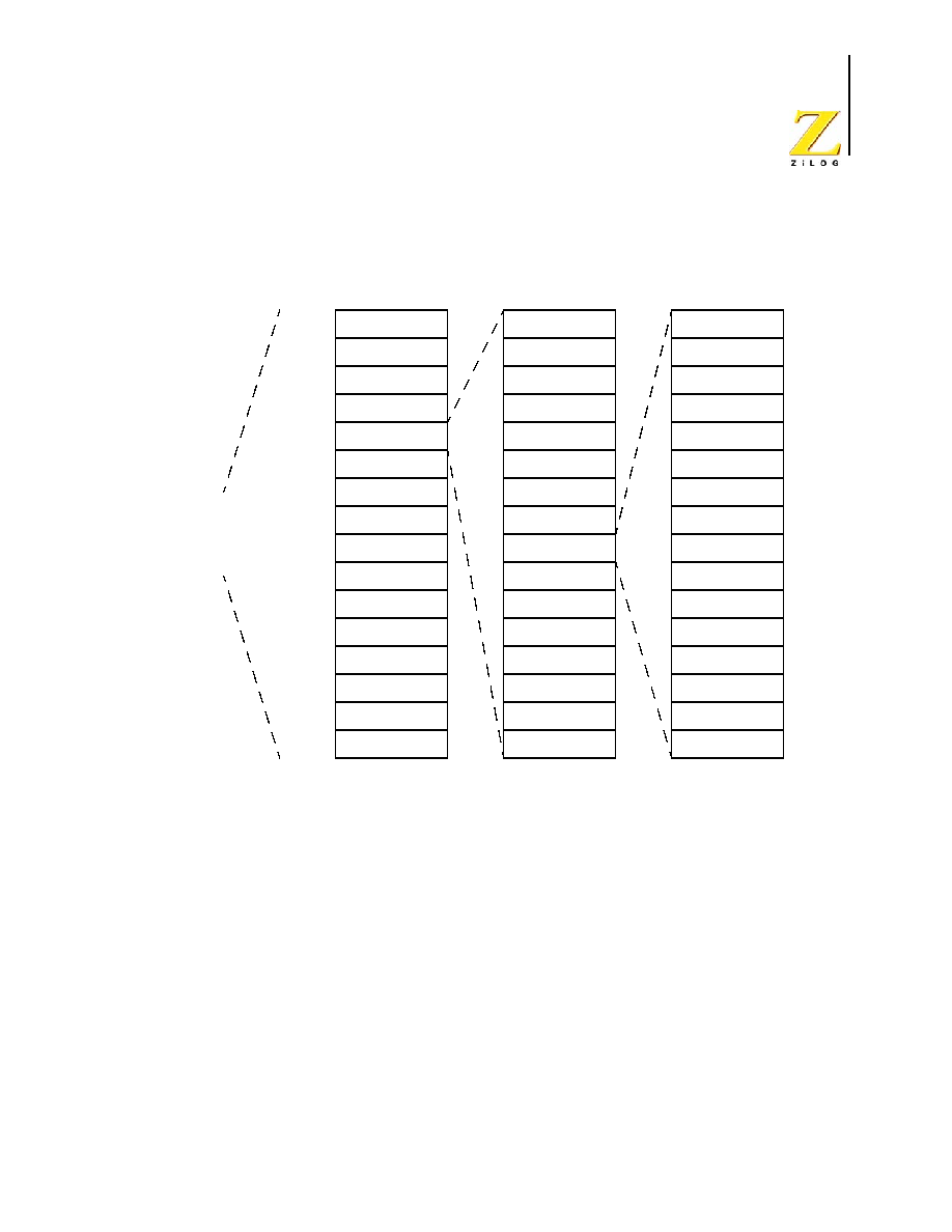
Register File Organization
The Register File can be accessed as a 4096 byte linear address space using 12-bit address-
ing mode, as sixteen 256-byte Register Pages using 8-bit addressing mode, or as sixteen
16-byte Working Register Groups per Register Page using 4-bit addressing mode. Figure 3
illustrates the organization of the Register File. Attempts to read unavailable Register File
addresses return an undefined value. Attempts to write to unavailable Register File
addresses produce no effect.
Table 6. eZ8 CPU Control Registers
Register
Mnemonic
Register Description
Address
(Hex)
FLAGS
Flags
FFC
RP
Register Pointer
FFD
SPH
Stack Pointer High Byte
FFE
SPL
Stack Pointer Low Byte
FFF
UM012811-0904
Address
Space
eZ8 CPU
User Manual
15
Figure 3. Register File Organization
Linear Addressing of the Register File
Using 12-bit linear addressing, the eZ8 CPU can directly access any 8-bit registers or 16-
bit register pairs within the 4096B Register File. The instructions that support 12-bit
addressing allow direct register access to most registers without requiring a change to the
value of the Register Pointer (RP). To accommodate the increase in the register address
space relative to the Z8
�
architecture, new Extended Addressing instructions have been
added to allow easier register access across page boundaries.
Page Mode Addressing of the Register File
In Page mode, the Register File is divided into sixteen 256-Byte register Pages. The cur-
rent page is determined by the Page Pointer value, RP[3:0]. Registers can be accessed by
Direct, Indirect, or Indexed Addressing using 8-bit addresses. The full 12-bit address is
given by {RP[3:0], Address[7:0]}. All 256 registers on the current page can be referenced
0
16
256B Pages
1
2
3
4
5
6
7
8
9
A
B
C
D
E
F
16
16B Working Register
Groups Per Page
0
1
2
3
4
5
6
7
8
9
A
B
C
D
E
F
000H
FFFH
4096B
Linear Addressable
Register File
16
Working Registers
Per Group
0
1
2
3
4
5
6
7
8
9
A
B
C
D
E
F

UM012811-0904
Address
Space
eZ8 CPU
User Manual
16
or modified by any instruction that uses 8-bit addressing. To change to a different page,
use the Set Register Pointer (SRP) instruction to change the value of the Register Pointer.
(Load instructions, LD or LDX, can also be used but require more bytes of code space).
Working Register Addressing of the Register File
Each Register File page is logically divided into 16 Working Register Groups of 16 regis-
ters each. The Working Registers within each Working Register Group are accessible
using 4-bit addressing. The high nibble of the eZ8 CPU Register Pointer (RP) contains the
base address of the active Working Register Group, referred to as the Working Group
Pointer. When accessing one of the Working Registers, the 4-bit address of the Working
Register is combined within the Page Pointer and the Working Group Pointer to form the
full 12-bit address {RP[3:0], RP[7:4], Address[3:0]}. Figure 4 illustrates this operation.
Figure 4. Working Register Addressing Example
Because Working Registers can typically be specified using fewer operand bytes, there are
fewer bytes of code needed, which reduces execution time. In addition, when processing
interrupts or changing tasks, the Register Pointer speeds context switching. The Set Regis-
ter Pointer (SRP) instruction sets the contents of the Register Pointer.
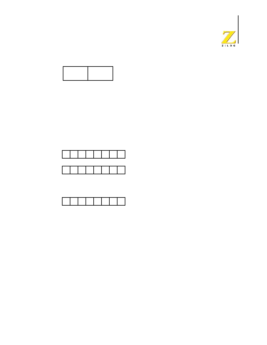
16-bit Register Pairs
Register data may be accessed as a 16-bit word using Register Pairs. In this case, the most
significant byte (MSB) of the data is stored in the even numbered register, while the least
significant byte (LSB) is stored in the next higher odd numbered register (see Figure 5).
Address the register pair using the address of the MSB.
0
1
1
1
0
0
1
1
Register Pointer
0
1
1
0
1
1
1
0
INC R6
0
1
1
1
0
1
1
0
Bit
0
Bit
7
0
0
1
1
Full 12-bit Register Address (376H)
Bit
11
Bit
0
Working Group
Page
Working Register
4-bit Address
UM012811-0904
Address
Space
eZ8 CPU
User Manual
17
Figure 5. 16-Bit Register Pair Addressing
Bit Addressing
Many eZ8 CPU instructions allow access to individual bits within registers. Figure 6 illus-
trates how the instruction AND R15, MASK can clear an individual bit.
Figure 6. Bit Addressing Example
Register File Precautions
Some control registers within the Register File provide Read-Only or Write-Only access.
When accessing these Read-Only or Write-Only registers, insure that the instructions do
not attempt to read from a Write-Only register or, conversely, write to a Read-Only regis-
ter. To determine which control registers allow either Read-Only or Write-Only access,
refer to the device-specific Product Specification.
PROGRAM MEMORY
The eZ8 CPU can access 64KB (65,536 bytes) of Program Memory. The Program Mem-
ory provides storage for both executable program code and data. For each product within
the eZ8 CPU family, a block of Program Memory beginning at address
0000H
is reserved
for option bits, the Reset vector, the Watch-Dog Timer time-out vector, the Illegal Instruc-
tion Trap vector, and the Interrupt vectors. The rest of the Program Memory stores code
MSB
LSB
Rn Rn+1
n = Even Address
0
1
1
1
0
0
0
0
R15
1
1
0
1
1
1
1
1
MASK = DFH
0
1
0
1
0
0
0
0
R15
Bit
0
Bit
7
AND R15, DFH
; Clear Bit 5 of Working Register 15

UM012811-0904
Address
Space
eZ8 CPU
User Manual
18
and data. Program Memory is accessed using opcode fetches, operand fetches, and LDC/
LDCI instructions. Table 7 provides an example of a Program Memory map for a eZ8
CPU product with 64KB of Program Memory and 16 interrupt vectors.
Individual products containing the eZ8 CPU support varying amounts of Program Mem-
ory. Refer to the device-specific Product Specification for your product to determine the
amount of Program Memory available. Attempts to read or execute from unavailable Pro-
gram Memory addresses return
FFH
. Attempts to write to unavailable Program Memory
addresses produce no effect.
DATA MEMORY
In addition to the Register File and the Program Memory, the eZ8 CPU also accesses a
maximum of 64KB (65,536 bytes) of Data Memory. The Data Memory space provides
data storage only. Opcode and operand fetches cannot be executed out of this space.
Access is obtained by the use of the LDE and LDEI instructions. Valid addresses for the
Data Memory are from
0000H
to
FFFFH
.
Individual products containing the eZ8 CPU support varying amounts of Data Memory.
Refer to the device-specific Product Specification for your product to determine the
amount of Data Memory available. Attempts to read unavailable Data Memory addresses
returns
FFH
. Attempts to write to unavailable Data Memory addresses produce no effect.
STACKS
Stack operations occur in the general-purpose registers of the Register File. The Register
Pair
FFEH
and
FFFH
form the 16-bit Stack Pointer (SP) used for all stack operations. The
Stack Pointer holds the current stack address. The Stack Pointer must be always be set to
point to a section of the Register File that does not cause user program data to be over-
written. Even for linear program code that may not employ the stack for Call and/or Inter-
Table 7. Program Memory Map Example
Program Memory
Address (Hex)
Description
0000-0001
Option Bits
0002-0003
RESET Vector
0004-0005
Watch-Dog Timer Vector
0006-0007
Illegal Instruction Trap Vector
0008-0027
Interrupt Vectors
0028-FFFF
Program code and data

UM012811-0904
Address
Space
eZ8 CPU
User Manual
19
rupt routines, the Stack Pointer must be set to prepare for possible Illegal Instruction
Traps.
The stack address decrements prior to a PUSH operation and increments after a POP oper-
ation. The stack address always points to the data stored at the top of the stack. The stack
is a return stack for interrupts and CALL and TRAP instructions. It can also be employed
as a data stack.
During a CALL instruction, the contents of the Program Counter are saved on the stack.
The Program Counter is restored during execution of a Return (RET). Interrupts and Traps
(either the TRAP instruction or an Illegal Instruction Trap) save the contents of the Pro-
gram Counter and the Flags Register on the stack. The Interrupt Return (IRET) instruction
restores them. Figure 7 illustrates the contents of the Stack and the location of the Stack
Pointer following Call, Interrupt and Trap operations.
Figure 7. Stack Operations
An overflow or underflow can occur when the stack address is incremented or decre-
mented beyond the available address space. The programmer must prevent this occurrence
or unpredictable operation will result.
PC[15:8]
PC[7:0]
Top of Stack
Flags
PC[15:8]
PC[7:0]
Top of Stack
Stack Contents
After an
Interrupt or Trap
Stack Contents
After a
Call Instruction

eZ8 CPU
User Manual
UM012811-0904
Addressing
Modes
20
Addressing Modes
INTRODUCTION
The eZ8 CPU provides six addressing modes:
�
Register (R)
�
Indirect Register (IR)
�
Indexed (X)
�
Direct (DA)
�
Relative (RA)
�
Immediate Data (IM)
With the exception of immediate data and condition codes, all operands are expressed as
either Register File, Program Memory, or Data Memory addresses. Registers use 12-bit
addresses in the range of
000H
-
FFFH
. Program Memory and Data Memory use 16-bit
addresses (register pairs) in the range of
0000H
-
FFFFH
.
Register pairs can designate 16-bit values or memory addresses. Working Register Pairs
use 4-bit addresses and must be specified as an even-numbered address in the range of 0,
2, ..., 14. Register Pairs use 8-bit addresses and must be specified as an even-numbered
address in the range of 0, 2, ..., 254.
In the following definitions of Addressing Modes, the use of 'register' can imply a Regis-
ter, a Register Pair, a Working Register, or a Working Register pair, depending on the con-
text.
Refer to the device-specific Product Specification for details of the Program, Data, and
Register File memory types and address ranges available.
REGISTER ADDRESSING (R)
Register Addressing Using 12-Bit Addresses
Extended register addressing is used to directly access any register in the Register File.
The 12-bit address is supplied in the operands. There are two types of extended mode
instructions: Register to Register operations and Immediate to Register operations.
Figure 8 illustrates Register addressing using 12-bit addresses.
UM012811-0904
Addressing
Modes
eZ8 CPU
User Manual
21
Figure 8. Register Addressing Using 12-Bit Addresses
Register Addressing Using 8-Bit Addresses
Registers or Register Pairs may be accessed using 8-bit addresses supplied in the oper-
ands. Any of the 256 registers on the current Register File Page can be accessed using 8-
bit addressing. The upper 4-bits of the 12-bit address is provided by the Page Pointer,
RP[3:0]. The full 12-bit address is given by {RP[3:0], Address[7:0]}.
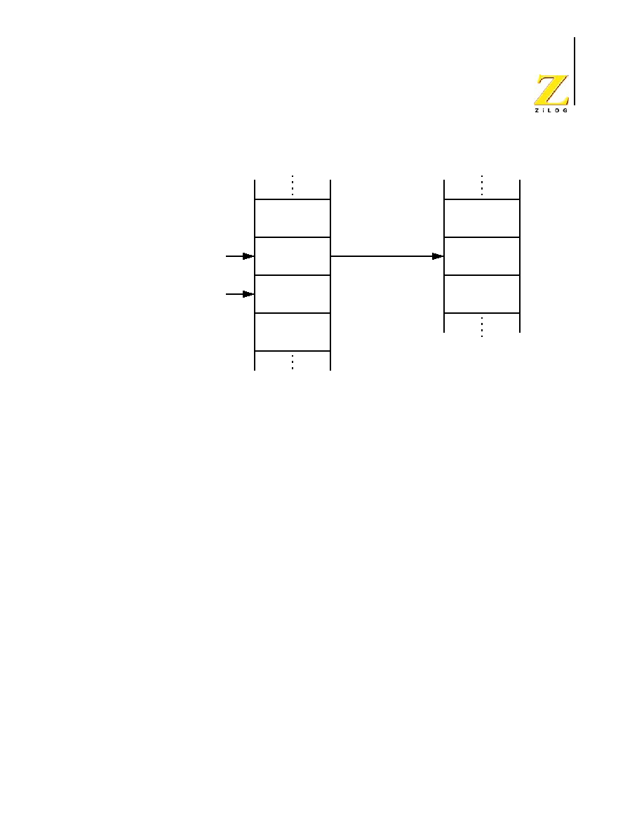
Figure 9 illustrates using 8-bit addressing, the destination and/or source address specified
corresponds to the a register in the Register File.
Two 12-bit
Program Memory
Addresses
(dst, src)
Three Operand
Instruction
(Example)
Opcode
src[11:4]
{src[3:0},
dst[11:8]}
dst[7:0]
Source
Destination
Register File
Register
Register
12-bit address is
dst[11:0]
12-bit address is
src[11:0]
UM012811-0904
Addressing
Modes
eZ8 CPU
User Manual
22
Figure 9. Register Addressing Using 8-Bit Addresses
Register Addressing Using 4-Bit Addresses
Working Registers or Working Register Pairs may be accessed using 4-bit addresses sup-
plied in the operands. With 4-bit Addressing, the destination and/or source addresses point
to one of the 16 possible Working Registers within the current Working Register Group.
This 4-bit address is combined with the Page Pointer, RP[3:0], and the Working Group
Pointer, RP[7:4], to form the actual 12-bit address in the Register File. The full 12-bit
address is given by {RP[3:0], RP[7:4], Address[3:0]}. Figure 10 illustrates 4-bit address-
ing of the Register File.
One 8-bit
Program Memory
Address
(dst)
One Operand
Instruction
(Example)
Opcode
dst[7:0]
Destination
Register File
Register
12-bit address is
{RP[3:0], dst[7:0]}
UM012811-0904
Addressing
Modes
eZ8 CPU
User Manual
23
Figure 10. Register Addressing Using 4-Bit Addresses
Escaped Mode Addressing
Escaped Mode Addressing with 8-bit Addresses
Using Escaped Mode Addressing 12-bit addresses can specify a Working Register. If the
high nibble of the 8-bit address is
EH
(1110b), a Working Register is inferred. For exam-
ple, if Working Register R12 (
CH
) is the desired destination operand, use
ECH
as the 8-bit
address operand in the opcode. To access Registers with addresses
E0H
to
EFH
, either set
the Working Group Pointer, RP[7:4], to
EH
or use indirect addressing.
Escaped Mode Addressing with 12-bit Addresses
Using Escaped Mode Addressing, address mode ER for the source or destination can spec-
ify a Working Register with 4-bit addressing.
If the high byte of the source or destination address is EEH (11101110B), a Working Reg-
ister is inferred. For example, the operand EE3H selects Working Register R3. The full 12-
bit address is given by {RP[3:0], RP[7:4], 3H}.
To access Registers on Page EH (addresses E00H to EFFH), set the Page Pointer, RP[3:0],
to EH and set the Working Group Pointer, RP[7:4], to the desired Working Group.
Two 4-bit
Program Memory
Addresses
(dst, src)
One Operand
Instruction
(Example)
Opcode
{dst[3:0],
12-bit address is
{RP[3:0], RP[7:4], dst[3:0]}
src[3:0]}
Source
Destination
Register
Register
Register File
12-bit address is
{RP[3:0], RP[7:4], src[3:0]}
UM012811-0904
Addressing
Modes
eZ8 CPU
User Manual
24
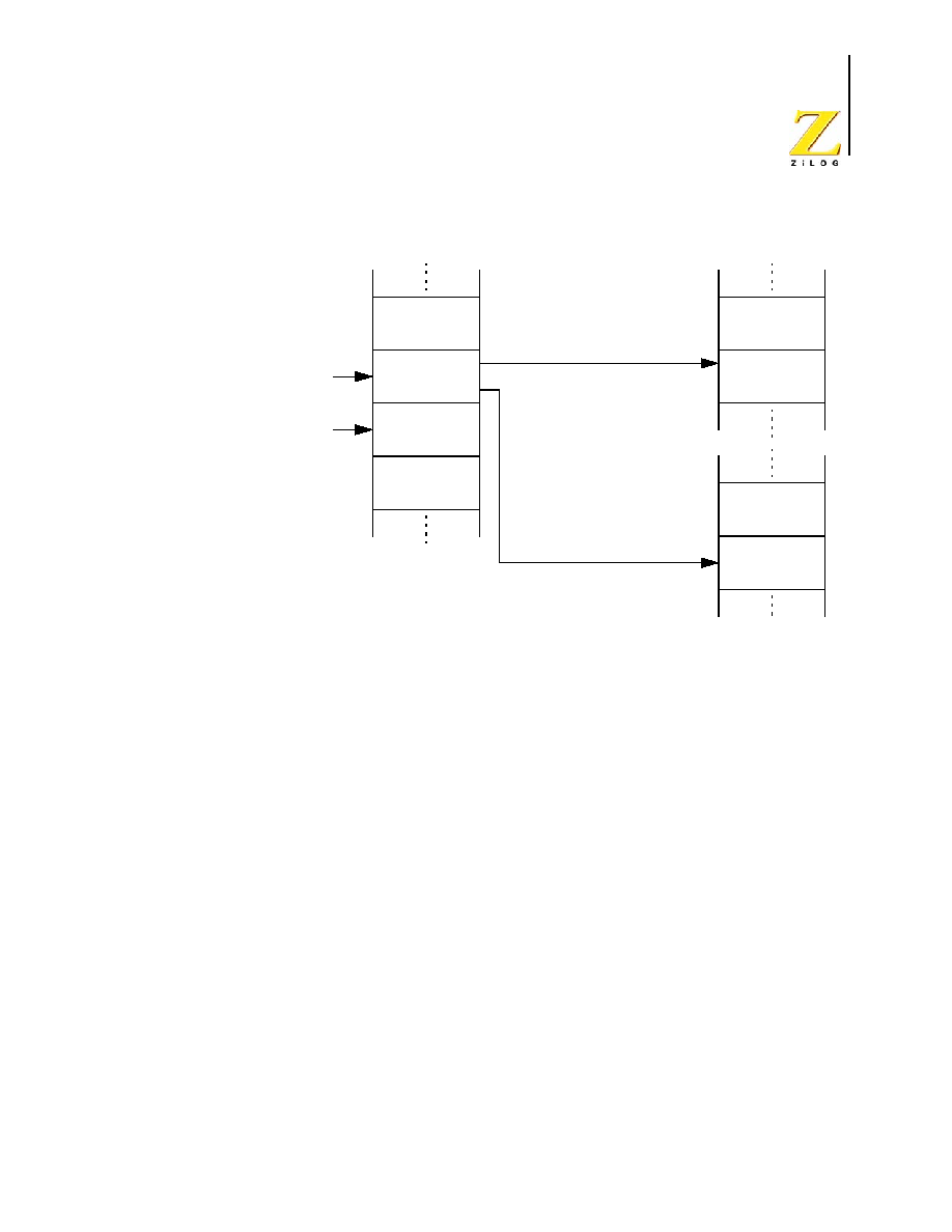
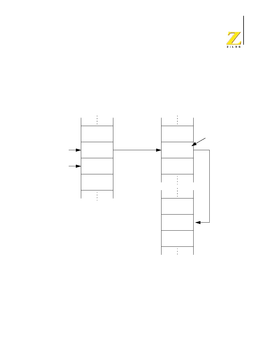
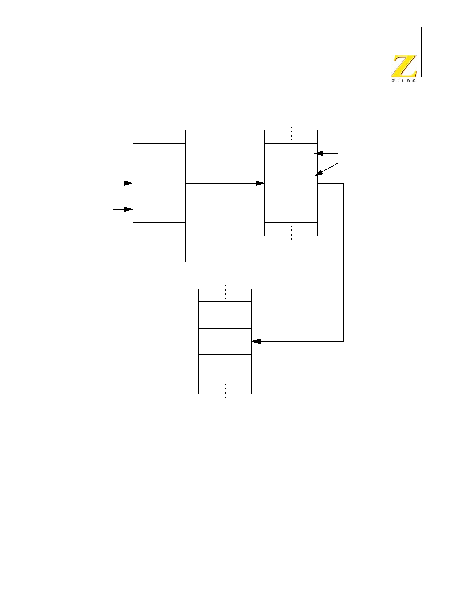
INDIRECT REGISTER ADDRESSING (IR)
In Indirect Register Addressing Mode, the contents of the specified Register provide an
address as illustrated in Figures 11 and 12. Depending upon the instruction selected, the
specified Register contents point to a Register File, Program Memory, or an Data Memory
location. When accessing Program Memory or Data Memory, Register Pairs or Working
Register Pairs hold the 16-bit addresses.
Figure 11. Indirect Register Addressing to Register File
One 8-bit
Program Memory
Address
(dst)
One Operand
Instruction
(Example)
Opcode
dst[7:0]
Destination
Register File
Register
12-bit address is
{RP[3:0], dst[7:0]}
Value used
in execution
Register
contains 8-bit
address (addr[7:0])
12-bit address is
{RP[3:0], ad
dr[7
:0
]}
UM012811-0904
Addressing
Modes
eZ8 CPU
User Manual
25
Figure 12. Indirect Register Addressing to Program or Data Memory
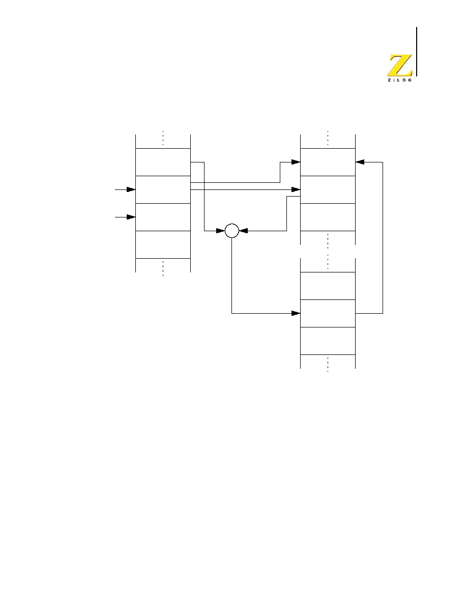
INDEXED ADDRESSING (X)
An Indexed Address consists of an 8-bit address contained in a Working Register offset by
an 8-bit Signed Index value. Figure 13 illustrates Indexed Addressing.
One 8-bit
Program Memory
Address
(dst)
One Operand
Instruction
(Example)
Opcode
dst[7:0]
Destination
Register File
Register MSB
12-bit address is
{RP[3:0], dst[7:0]}
Value used
in execution
Register Pair
contains two
8-bit address
16
-b
it ad
dress is
{a
ddr[15:8
]
, add
r[7:0]}
Program or Data Memory
Destination
Register LSB
{addr[15:8], addr[7:0]}
UM012811-0904
Addressing
Modes
eZ8 CPU
User Manual
26
Figure 13. Indexed Register Addressing
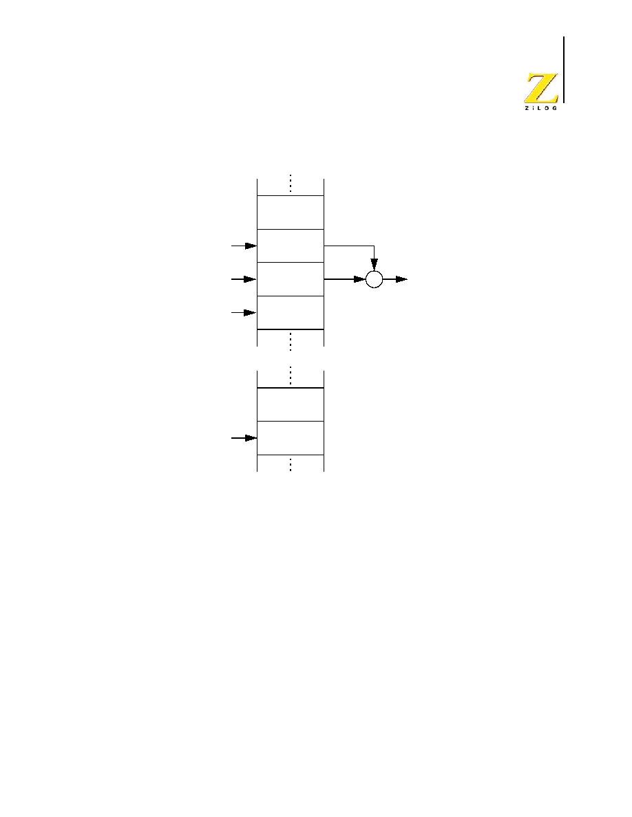
DIRECT ADDRESSING (DA)
Figure 14 depicts the Direct Addressing mode.This instruction specifies the address of the
next instruction to be executed. Only the Jump (JP and JP cc) and Call (CALL) instruc-
tions use Direct Addressing. The 16-bit Direct Address is written to the Program Counter.
Two 4-bit
Program Memory
Address
(dst, src)
Two Operand
Instruction
(Example)
Opcode
{dst[3:0],
Destination
Register File
Register
12-bit address is
{RP[3:0], RP[7:4], dst[3:0]}
Value used
in execution
8-
bi
t
va
l
u
e
w
r
i
t
t
e
n
to
De
si
t
n
a
t
i
o
n
Re
gi
st
er
src[3:0]}
Index
+
Source
Register
Source
Value
12-bit address is
{RP[3:0], Source Value + Index}
UM012811-0904
Addressing
Modes
eZ8 CPU
User Manual
27
Figure 14. Direct Addressing
RELATIVE ADDRESSING (RA)
Figure 15 illustrates the Relative Addressing mode. The instruction specifies a two's com-
plement signed displacement in the range of �128 to +127. This instruction, added to the
contents of the Program Counter, obtains the address of the next instruction to be exe-
cuted. Prior to the addition operation, the Program Counter contains the address of the
instruction immediately following the current relative addressing instruction. The JR and
DJNZ instructions are the only instructions that use this mode.
16-bit Direct
Program Memory
Address
Two Operand
Instruction
(Example)
Opcode
DA[15:8]
DA[7:0]
Next
Opcode
16-bit Program
Memory address
is DA[15:0]
DA[15:0] written to
Program Counter
UM012811-0904
Addressing
Modes
eZ8 CPU
User Manual
28
Figure 15. Relative Addressing
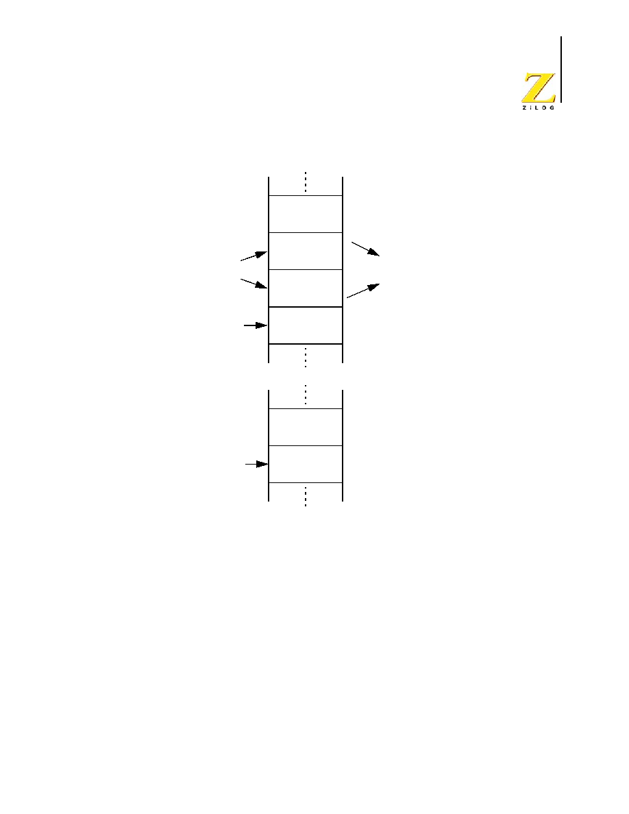
IMMEDIATE DATA ADDRESSING (IM)
Immediate data is considered an "addressing mode" for this discussion. It is the only
addressing mode that does not indicate a register or memory address as the operand. The
operand value used by the instruction is the value supplied in the operand field itself.
Because an immediate operand is part of the instruction, it is always located in the Pro-
gram Memory address space (see Figure 16).
8-bit Value
Program Memory
-128 to +127
One Operand
Instruction
(Example)
Opcode
Displacement
Next Opcode
Next Opcode
if Jump
16-bit Program
Memory address
is PC[15:0] + d[7:0]
if no Jump
+
PC[15:0]
d
If Jump taken,
PC[15:0] = PC[15:0] + d[7:0]
16-bit Program
Memory address
is PC[15:0]
UM012811-0904
Addressing
Modes
eZ8 CPU
User Manual
29
Figure 16. Immediate Data Addressing
Program Memory
Two Operand
Instruction
(Example)
Opcode
dst
Immediate
Data
Register File
12-bit address is
{RP[3:0], dst[7:0]}
Destination
Register
8-bit data written
to Destination

eZ8 CPU
User Manual
UM012811-0904
Interrupts
30
Interrupts
INTRODUCTION
Interrupt requests (IRQs) allow peripheral devices to suspend CPU operation and force the
CPU to start an interrupt service routine (ISR). The interrupt service routine exchanges
data, status information, or control information between the CPU and the interrupting
peripheral. When the service routine finishes, the CPU returns to the previous operation.
The eZ8 CPU supports both vectored-and polled-interrupt handling. Interrupts are gener-
ated from internal peripherals, external devices through the port pins, or software. The
Interrupt Controller prioritizes and handles individual interrupt requests before passing
them on to the eZ8 CPU.
The interrupt sources and trigger conditions are device dependent. Refer to the device-spe-
cific Product Specification to determine available interrupt sources (internal and external),
triggering edge options, and exact programming details.
INTERRUPT ENABLE AND DISABLE
Interrupts are globally enabled and disabled by executing the Enable Interrupts (EI) and
Disable Interrupts (DI) instructions, respectively. These instructions affect the global
interrupt enable control bit in the Interrupt Controller. Enable or disable the individual
interrupts using control registers in the Interrupt Controller. Refer to the device-specific
Product Specification for information on the Interrupt Controller.
INTERRUPT PRIORITY
The Interrupt Controller prioritizes all interrupts. Refer to the device-specific Product
Specification for information on the Interrupt Controller.
VECTORED INTERRUPT PROCESSING
Each eZ8 CPU interrupt is assigned its own vector. When an interrupt occurs, control
passes to the interrupt service routine pointed to by the interrupt's vector location in Pro-
gram Memory. The sequence of events for a vectored interrupt is as follows:

UM012811-0904
Interrupts
eZ8 CPU
User Manual
31
1. Push the low byte of the Program Counter, PC[7:0], on the stack.
2. Push the high byte of the Program Counter, PC[15:8], on the stack.
3. Push the Flags Register on the stack.
4. Fetch the High Byte of the Interrupt Vector
5. Fetch the Low Byte of the Interrupt Vector
6. Branch to the Interrupt Service Routine specified by the Interrupt Vector
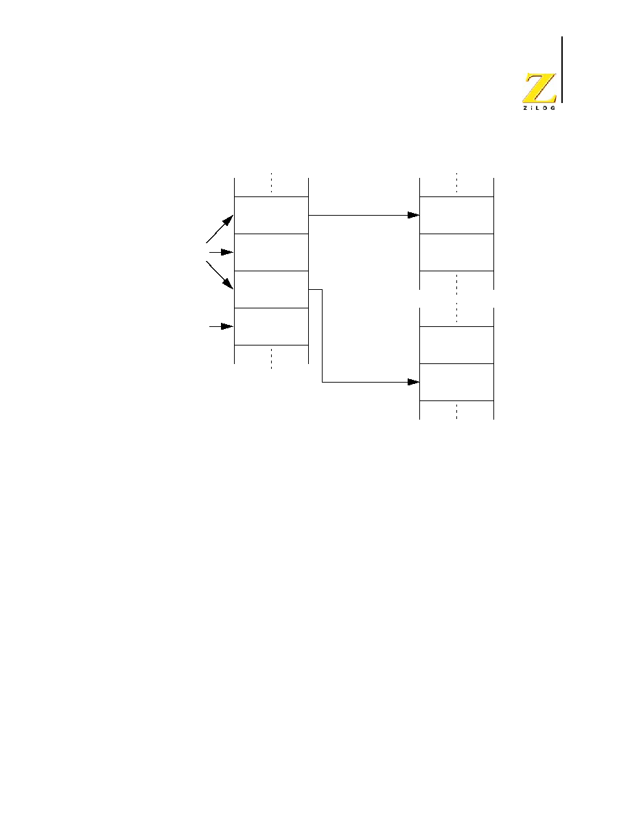
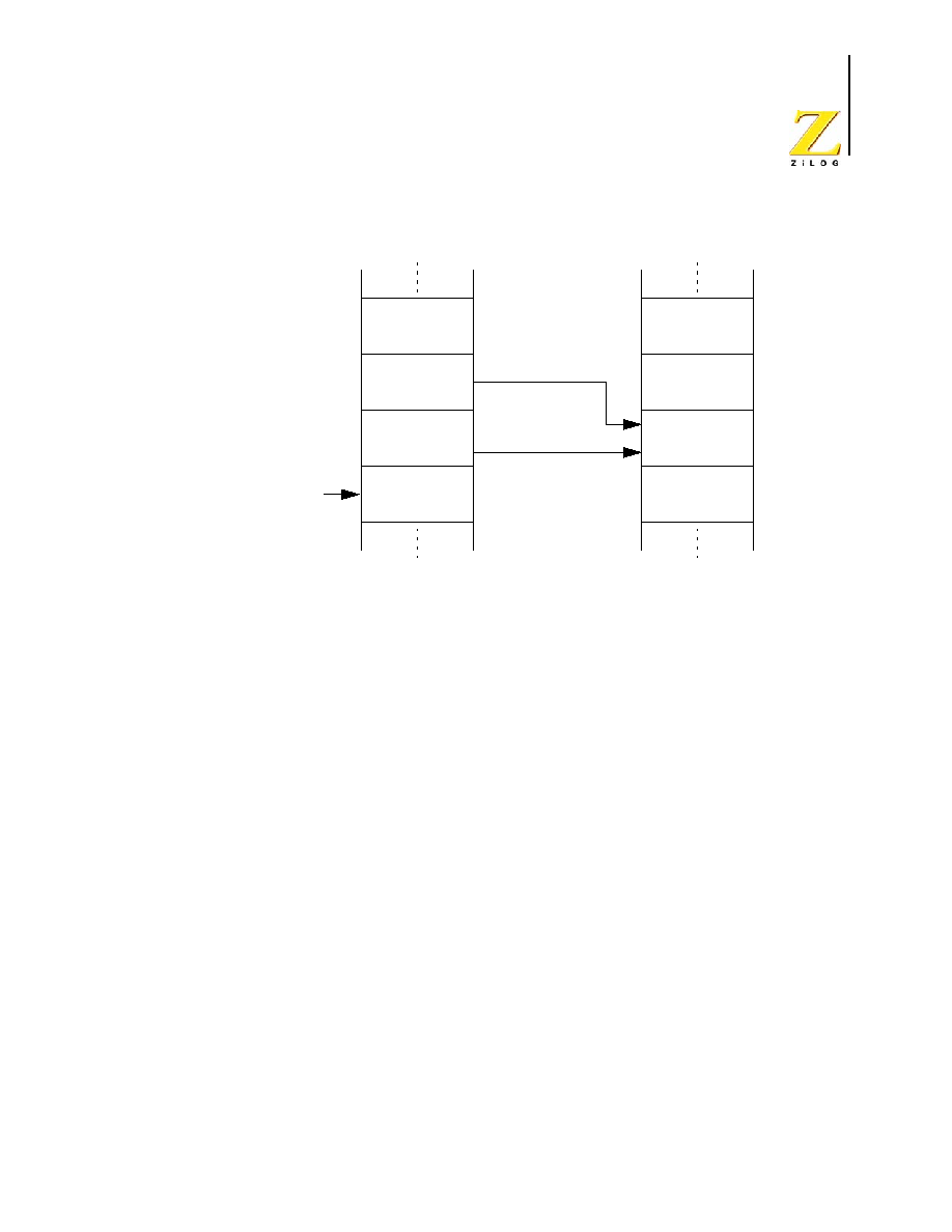
Figure 17 illustrates the effect of vectored interrupts on the Stack Pointer and the contents
of the stack. Figure 18 provides an example of the Program Memory during interrupt oper-
ation. In the example of Figure 18, the Interrupt Vector is located at address
0014H
in Pro-
gram Memory. The 2-byte Interrupt Vector, stored at Program Memory addresses
0014H
and
0015H
, is loaded into the Program Counter. Execution of the Interrupt Service Rou-
tine begins at Program Memory address
4567H
, as is stored in the Interrupt Vector.
Figure 17. Effects of an Interrupt on the Stack
Top of Stack
Stack Pointer
Flags[7:0]
PC[15:8]
PC[7:0]
Stack Pointer
Stack Pointer and Stack
Before an Interrupt
Stack Pointer and Stack
After an Interrupt

UM012811-0904
Interrupts
eZ8 CPU
User Manual
32
Figure 18. Interrupt Vectoring in Program Memory Example
NESTING OF VECTORED INTERRUPTS
Vectored interrupt nesting allows higher priority requests to interrupt a lower priority
request. To initiate vectored interrupt nesting, perform the following steps during the inter-
rupt service routine:
1. Push the old Interrupt Control and Interrupt Enable Register information on the stack.
2. Load the Interrupt Enable Register information with new masks to disable lower
priority interrupts.
3. Execute an EI instruction to enable the interrupts.
4. Proceed with the interrupt service routine processing.
5. After processing is complete, execute a DI instruction to disable the interrupts.
6. Restore the Interrupt Control and Interrupt Enable Register information from the
stack.
7. Execute an IRET instruction to return from the interrupt service routine.
Program Memory
Vector Selected by
Interrupt Controller
Interrupt
Vector
Table
Interrupt Service
Routine Origin
Vector[15:8] = 45H
Vector[7:0] = 67H
4567H
Program Memory
Address
0014H
0015H

UM012811-0904
Interrupts
eZ8 CPU
User Manual
33
POLLED INTERRUPT PROCESSING
Polled interrupt processing is supported by individually disabling the interrupts to be
polled. To initiate polled processing, check the interrupt bits of interest in the Interrupt
Request Register(s) using the Test Under Mask (TM) or similar bit test instruction. If the
bit is 1, perform a software call or branch to the interrupt service routine. Write the service
routine to service the request, reset the Interrupt Request Bit in the Interrupt Request Reg-
ister, and return or branch back to the main program. An example of a polling routine fol-
lows:
TM
IRQ1, #0010000B
; Test for interrupt request in Bit 5 of IRQ1
JR
Z, NEXT
; If no interrupt request, go to NEXT
CALL SERVICE
; If interrupt request, go to the interrupt service
; routine.
NEXT:
Other program code here
SERVICE:
; Process interrupt request
Service routine code here
AND IRQ1, #1101111B
; Clear the interrupt request in Bit 5 of IRQ1
RET
; Return to address following the CALL
Refer to the device-specific Product Specification for information on the Interrupt Request
Registers.
SOFTWARE INTERRUPT GENERATION
The eZ8 CPU generates Software Interrupts by writing to the Interrupt Request Registers
in the Register File. The Interrupt Controller and eZ8 CPU handle these software inter-
rupts in the same manner as hardware-generated interrupt requests. To generate a Software
Interrupt, write a 1 to the desired interrupt request bit in the selected Interrupt Request
Register. As an example, the following instruction
OR IRQ1, #0010000B
writes a 1 to Bit 5 of Interrupt Request Register 1. If this interrupt at Bit 5 is enabled and
there are no higher priority pending interrupt requests, program control transfers to the
interrupt service routine specified by the corresponding Interrupt Vector.
For more information on the Interrupt Controller and Interrupt Request Registers, refer to
the device-specific Product Specification.

eZ8 CPU
User Manual
UM012811-0904
Illegal
Instruction
Traps
34
Illegal Instruction Traps
Description
The instruction set of the eZ8 CPU does not cover all possible sequences of binary values.
Binary values and sequences for which no operation is defined are illegal instructions.
When the eZ8 CPU fetches one of these illegal instructions, it performs an Illegal Instruc-
tion Trap operation.
The Illegal Instruction Trap functions similarly to a TRAP #%3 instruction (object code
F2H
03H
). The Flags and Program Counter are pushed on the stack. When the Program
Counter detects an illegal instruction it does not increment. The Program Counter value
that is pushed onto the stack points to the illegal instruction.
The most significant byte (MSB) of the Illegal Instruction Trap Vector is stored at Pro-
gram Memory address
0006H
. The least significant byte (LSB) of the Illegal Instruction
Trap Vector is stored at Program Memory address
0007H
. The 16-bit Illegal Instruction
Trap Vector replaces the value in the Program Counter (PC). Program execution resumes
from the new value in the Program Counter.
An IRET instruction must not be performed following an Illegal Instruction Trap
service routine. Because the stack contains the Program Counter value of the il-
legal instruction, the IRET instruction returns the code execution to this illegal
instruction.
Symbolic Operation of an Illegal Instruction Trap
SP
SP - 2
@SP
PC
SP
SP - 1
@SP
Flags
PC
Vector
Linear Programs that do not Employ the Stack
The Stack Pointer must point to a section of the Register File that does not overwrite user
program data. Even for linear program code that may not employ the stack for Call and/or
Interrupt routines, set the Stack Pointer to prepare for possible Illegal Instruction Traps.
Caution:

eZ8 CPU
User Manual
UM012811-0904
eZ8 CPU Instruction Set Summary
35
eZ8 CPU Instruction Set Summary
ASSEMBLY LANGUAGE PROGRAMMING INTRODUCTION
The eZ8 CPU assembly language enables writing to an application program without con-
cern about actual memory addresses or machine instruction formats. A program written in
assembly language is called a source program. Assembly language uses symbolic
addresses to identify memory locations. It also allows mnemonic codes (opcodes and
operands) to represent the instructions themselves. The opcodes identify the instruction
while the operands represent memory locations, registers, or immediate data values.
Each assembly language program consists of a series of symbolic commands, called state-
ments. Each statement contains labels, operations, operands and comments.
Labels are assigned to a particular instruction step in a source program. The label identi-
fies that step in the program as an entry point for use by other instructions.
The assembly language also includes assembler directives that supplement the machine
instruction. The assembler directives, or pseudo-ops, are not translated into a machine
instruction. The pseudo-ops are interpreted as directives that control or assist the assembly
process.
The assembler processes the source program to obtain a machine language program called
the object code. The eZ8 CPU executes the object code. An example segment of an assem-
bly language program is detailed in the following example.
Assembly Language Source Program Example
JP START
; Everything after the semicolon is a comment.
START:
; A label called "START". The first instruction (
JP START
) in this
; example causes program execution to jump to the point within the
; program where the
START
label occurs.
LD R4, R7
; A Load (LD) instruction with two operands. The first operand,
; Working Register R4, is the destination. The second operand,
; Working Register R7, is the source. The contents of R7 are
; written into R4.
LD 234H, #%01
; Another Load (LD) instruction with two operands.
; The first operand, Extended Mode Register Address
234H
,
; identifies the destination. The second operand, Immediate Data

UM012811-0904
eZ8 CPU Instruction Set Summary
eZ8 CPU
User Manual
36
; value
01H
, is the source. The value
01H
is written into the
; Register at address
234H
.
ASSEMBLY LANGUAGE SYNTAX
For proper instruction execution, eZ8 CPU assembly language syntax requires that the
operands be written as `destination, source'. After assembly, the object code usually places
the operands in the order 'source, destination', but ordering is opcode-dependent. The fol-
lowing instruction examples illustrate the format of some basic assembly instructions and
the resulting object code produced by the assembler. This binary format must be followed
by users that prefer manual program coding or intend to implement their own assembler.
Example 1: If the contents of Registers
43H
and
08H
are added and the result is stored in
43H
, the assembly syntax and resulting object code is:
Example 2: In general, when an instruction format requires an 8-bit register address, that
address can specify any register location in the range 0�255 or, using Escaped Mode
Addressing, a Working Register R0�R15. If the contents of Register 43H and Working
Register R8 are added and the result is stored in 43H, the assembly syntax and resulting
object code is:
See the device-specific Product Specification to determine the exact register file range
available. The register file size varies, depending on the device type.
EZ8 CPU INSTRUCTION NOTATION
In the eZ8 CPU Instruction Summary and Description sections, the operands, condition
codes, status flags, and address modes are represented by a notational shorthand that
Table 10 describes.
Table 8. Assembly Language Syntax Example 1
Assembly Language Code ADD
43H,
08H
(ADD dst, src)
Object Code
04
08
43
(OPC src, dst)
Table 9. Assembly Language Syntax Example 2
Assembly Language Code ADD
43H,
R8
(ADD dst, src)
Object Code
04
E8
43
(OPC src, dst)

UM012811-0904
eZ8 CPU Instruction Set Summary
eZ8 CPU
User Manual
37
.
Table 11 contains additional symbols that are used throughout the Instruction Summary
and Instruction Set Description sections.
Table 10. Notational Shorthand
Notation Description
Operand Range
b
Bit
b
b represents a value from 0 to 7 (000B to 111B).
cc
Condition Code
--
See Condition Codes overview in the Flags Register
section of the Architectural Overview chapter.
DA
Direct Address
Addrs
Addrs. represents a number in the range of 0000H to
FFFFH
ER
Extended Addressing Register
Reg
Reg. represents a number in the range of 000H to
FFFH
IM
Immediate Data
#Data
Data is a number between 00H to FFH
Ir
Indirect Working Register
@Rn
n = 0 �15
IR
Indirect Register
@Reg
Reg. represents a number in the range of 00H to FFH
Irr
Indirect Working Register Pair
@RRp
p = 0, 2, 4, 6, 8, 10, 12, or 14
IRR
Indirect Register Pair
@Reg
Reg. represents an even number in the range 00H to
FEH
p
Polarity
p
Polarity is a single bit binary value of either 0B or 1B.
r
Working Register
Rn
n = 0 � 15
R
Register
Reg
Reg. represents a number in the range of 00H to FFH
RA
Relative Address
X
X represents an index in the range of +127 to �128
which is an offset relative to the address of the next
instruction
rr
Working Register Pair
RRp
p = 0, 2, 4, 6, 8, 10, 12, or 14
RR
Register Pair
Reg
Reg. represents an even number in the range of 00H to
FEH
Vector
Vector Address
#Vector
Vector represents a number in the range of 00H to FFH
X
Indexed
#Index
The register or register pair to be indexed is offset by
the signed Index value (#Index) in a +127 to -128
range.

UM012811-0904
eZ8 CPU Instruction Set Summary
eZ8 CPU
User Manual
38
An arrow (
)
indicates assignment of a value. For example,
dst
dst + src
indicates the source data is added to the destination data and the result is stored in the des-
tination location.
EZ8 CPU INSTRUCTION CLASSES
eZ8 CPU instructions can be divided functionally into the following groups:
�
Arithmetic
�
Bit Manipulation
�
Block Transfer
�
CPU Control
�
Load
�
Logical
�
Program Control
�
Rotate and Shift
Table 11. Additional Symbols
Symbol
Definition
dst
Destination Operand
src
Source Operand
@
Indirect Address Prefix
C
Carry Flag
SP
Stack Pointer
PC
Program Counter
FLAGS
Flags Register
RP
Register Pointer
#
Immediate Operand Prefix
B
Binary Number Suffix
%
Hexadecimal Number Prefix
H
Hexadecimal Number Suffix

UM012811-0904
eZ8 CPU Instruction Set Summary
eZ8 CPU
User Manual
39
Tables 12 through 19 contain the instructions belonging to each group and the number of
operands required for each instruction. Some instructions appear in more than one table as
these instructions can be considered as a subset of more than one category. Within these
tables, the source operand is identified as 'src', the destination operand is 'dst' and a con-
dition code is 'cc'.
Table 12. Arithmetic Instructions
Mnemonic
Operands
Instruction
ADC
dst, src
Add with Carry
ADCX
dst, src
Add with Carry using Extended Addressing
ADD
dst, src
Add
ADDX
dst, src
Add using Extended Addressing
CP
dst, src
Compare
CPC
dst, src
Compare with Carry
CPCX
dst, src
Compare with Carry using Extended Addressing
CPX
dst, src
Compare using Extended Addressing
DA
dst
Decimal Adjust
DEC
dst
Decrement
DECW
dst
Decrement Word
INC
dst
Increment
INCW
dst
Increment Word
MULT
dst
Multiply
SBC
dst, src
Subtract with Carry
SBCX
dst, src
Subtract with Carry using Extended Addressing
SUB
dst, src
Subtract
SUBX
dst, src
Subtract using Extended Addressing
Table 13. Bit Manipulation Instructions
Mnemonic
Operands
Instruction
BCLR
bit, dst
Bit Clear
BIT
p, bit, dst
Bit Set or Clear
BSET
bit, dst
Bit Set

UM012811-0904
eZ8 CPU Instruction Set Summary
eZ8 CPU
User Manual
40
BSWAP
dst
Bit Swap
CCF
--
Complement Carry Flag
RCF
--
Reset Carry Flag
SCF
--
Set Carry Flag
TCM
dst, src
Test Complement Under Mask
TCMX
dst, src
Test Complement Under Mask using Extended Addressing
TM
dst, src
Test Under Mask
TMX
dst, src
Test Under Mask using Extended Addressing
Table 14. Block Transfer Instructions
Mnemonic
Operands
Instruction
LDCI
dst, src
Load Constant to/from Program Memory and Auto-Increment
Addresses
LDEI
dst, src
Load External Data to/from Data Memory and Auto-Increment
Addresses
Table 15. CPU Control Instructions
Mnemonic
Operands
Instruction
ATM
--
Atomic Execution
CCF
--
Complement Carry Flag
DI
--
Disable Interrupts
EI
--
Enable Interrupts
HALT
--
Halt Mode
NOP
--
No Operation
RCF
--
Reset Carry Flag
SCF
--
Set Carry Flag
SRP
src
Set Register Pointer
STOP
--
Stop Mode
WDT
--
Watch-Dog Timer Refresh
Table 13. Bit Manipulation Instructions (Continued)
Mnemonic
Operands
Instruction

UM012811-0904
eZ8 CPU Instruction Set Summary
eZ8 CPU
User Manual
41
Table 16. Load Instructions
Mnemonic Operands Instruction
CLR
dst
Clear
LD
dst, src
Load
LDC
dst, src
Load Constant to/from Program Memory
LDCI
dst, src
Load Constant to/from Program Memory and Auto-Increment
Addresses
LDE
dst, src
Load External Data to/from Data Memory
LDEI
dst, src
Load External Data to/from Data Memory and Auto-Increment
Addresses
LDWX
dst, src
Load Word using Extended Addressing
LDX
dst, src
Load using Extended Addressing
LEA
dst, X(src) Load Effective Address
POP
dst
Pop
POPX
dst
Pop using Extended Addressing
PUSH
src
Push
PUSHX
src
Push using Extended Addressing
Table 17. Logical Instructions
Mnemonic Operands Instruction
AND
dst, src
Logical AND
ANDX
dst, src
Logical AND using Extended Addressing
COM
dst
Complement
OR
dst, src
Logical OR
ORX
dst, src
Logical OR using Extended Addressing
XOR
dst, src
Logical Exclusive OR
XORX
dst, src
Logical Exclusive OR using Extended Addressing

UM012811-0904
eZ8 CPU Instruction Set Summary
eZ8 CPU
User Manual
42
Table 18. Program Control Instructions
Mnemonic
Operands
Instruction
BRK
--
On-Chip Debugger Break
BTJ
p, bit, src, DA Bit Test and Jump
BTJNZ
bit, src, DA
Bit Test and Jump if Non-Zero
BTJZ
bit, src, DA
Bit Test and Jump if Zero
CALL
dst
Call Procedure
DJNZ
dst, dst, RA
Decrement and Jump Non-Zero
IRET
--
Interrupt Return
JP
dst
Jump
JP cc
dst
Jump Conditional
JR
DA
Jump Relative
JR cc
DA
Jump Relative Conditional
RET
--
Return
TRAP
vector
Software Trap
Table 19. Rotate and Shift Instructions
Mnemonic
Operands
Instruction
BSWAP
dst
Bit Swap
RL
dst
Rotate Left
RLC
dst
Rotate Left through Carry
RR
dst
Rotate Right
RRC
dst
Rotate Right through Carry
SRA
dst
Shift Right Arithmetic
SRL
dst
Shift Right Logical
SWAP
dst
Swap Nibbles

UM012811-0904
eZ8 CPU Instruction Set Summary
eZ8 CPU
User Manual
43
EZ8 CPU INSTRUCTION SUMMARY
Table 20 summarizes the eZ8 CPU instructions. The table identifies the addressing modes
employed by the instruction, the effect upon the Flags register, the number of CPU clock
cycles required for the instruction fetch, and the number of CPU clock cycles required for
the instruction execution.
.
Table 20. eZ8 CPU Instruction Summary
Assembly
Mnemonic
Symbolic Operation
Address Mode
Opcode(s)
(Hex)
Flags
Fetch
Cycles
Instr.
Cycles
dst
src
C Z S
V D H
ADC dst, src
dst
dst + src + C
r
r
12
*
*
*
*
0
*
2
3
r
Ir
13
2
4
R
R
14
3
3
R
IR
15
3
4
R
IM
16
3
3
IR
IM
17
3
4
ADCX dst, src
dst
dst + src + C
ER
ER
18
*
*
*
*
0
*
4
3
ER
IM
19
4
3
ADD dst, src
dst
dst + src
r
r
02
*
*
*
*
0
*
2
3
r
Ir
03
2
4
R
R
04
3
3
R
IR
05
3
4
R
IM
06
3
3
IR
IM
07
3
4
ADDX dst, src
dst
dst + src
ER
ER
08
*
*
*
*
0
*
4
3
ER
IM
09
4
3
Flags Notation:
* = Value is a function of the result of the operation.
- = Unaffected
X = Undefined
C = Carry Flag
0 = Reset to 0
1 = Set to 1
UM012811-0904
eZ8 CPU Instruction Set Summary
eZ8 CPU
User Manual
44
AND dst, src
dst
dst AND src
r
r
52
-
*
*
0
-
-
2
3
r
Ir
53
2
4
R
R
54
3
3
R
IR
55
3
4
R
IM
56
3
3
IR
IM
57
3
4
ANDX dst, src
dst
dst AND src
ER
ER
58
-
*
*
0
-
-
4
3
ER
IM
59
4
3
ATM
Block all interrupt and
DMA requests during
execution of the next 3
instructions
2F
-
-
-
-
-
-
1
2
BCLR bit, dst
dst[bit]
0
r
E2
-
*
*
0
-
-
2
2
BIT p, bit, dst
dst[bit]
p
r
E2
-
*
*
0
-
-
2
2
BRK
Debugger Break
00
-
-
-
-
-
-
1
2
BSET bit, dst
dst[bit]
1
r
E2
-
*
*
0
-
-
2
2
BSWAP dst
dst[7:0]
dst[0:7]
R
D5
X *
*
0
-
-
2
2
BTJ p, bit, src, dst if src[bit] = p
PC
PC + X
r
F6
-
-
-
-
-
-
3
3
Ir
F7
3
4
BTJNZ bit, src, dst if src[bit] = 1
PC
PC + X
r
F6
-
-
-
-
-
-
3
3
Ir
F7
3
4
BTJZ bit, src, dst
if src[bit] = 0
PC
PC + X
r
F6
-
-
-
-
-
-
3
3
Ir
F7
3
4
CALL dst
SP
SP -2
@SP
PC
PC
dst
IRR
D4
-
-
-
-
-
-
2
6
DA
D6
3
3
CCF
C
~C
EF
*
-
-
-
-
-
1
2
Table 20. eZ8 CPU Instruction Summary (Continued)
Assembly
Mnemonic
Symbolic Operation
Address Mode
Opcode(s)
(Hex)
Flags
Fetch
Cycles
Instr.
Cycles
dst
src
C Z S
V D H
Flags Notation:
* = Value is a function of the result of the operation.
- = Unaffected
X = Undefined
C = Carry Flag
0 = Reset to 0
1 = Set to 1
UM012811-0904
eZ8 CPU Instruction Set Summary
eZ8 CPU
User Manual
45
CLR dst
dst
00H
R
B0
-
-
-
-
-
-
2
2
IR
B1
2
3
COM dst
dst
~dst
R
60
-
*
*
0
-
-
2
2
IR
61
2
3
CP dst, src
dst - src - C
r
r
A2
*
*
*
*
-
-
2
3
r
Ir
A3
2
4
R
R
A4
3
3
R
IR
A5
3
4
R
IM
A6
3
3
IR
IM
A7
3
4
CPC dst, src
dst - src - C
r
r
1F A2
*
*
*
*
-
-
3
3
r
Ir
1F A3
3
4
R
R
1F A4
4
3
R
IR
1F A5
4
4
R
IM
1F A6
4
3
IR
IM
1F A7
4
4
CPCX dst, src
dst - src - C
ER
ER
1F A8
*
*
*
*
-
-
5
3
ER
IM
1F A9
5
3
CPX dst, src
dst - src
ER
ER
A8
*
*
*
*
-
-
4
3
ER
IM
A9
4
3
DA dst
dst
DA(dst)
R
40
*
*
* X
-
-
2
2
IR
41
2
3
DEC dst
dst
dst - 1
R
30
-
*
*
*
-
-
2
2
IR
31
2
3
Table 20. eZ8 CPU Instruction Summary (Continued)
Assembly
Mnemonic
Symbolic Operation
Address Mode
Opcode(s)
(Hex)
Flags
Fetch
Cycles
Instr.
Cycles
dst
src
C Z S
V D H
Flags Notation:
* = Value is a function of the result of the operation.
- = Unaffected
X = Undefined
C = Carry Flag
0 = Reset to 0
1 = Set to 1

UM012811-0904
eZ8 CPU Instruction Set Summary
eZ8 CPU
User Manual
46
DECW dst
dst
dst - 1
RR
80
-
*
*
*
-
-
2
5
IR
81
2
6
DI
Disable Interrupts
IRQCTL[7]
0
8F
-
-
-
-
-
-
1
2
DJNZ dst, RA
dst
dst � 1
if dst
0
PC
PC + X
r
0A-FA
-
-
-
-
-
-
2
3
EI
Enable Interrupts
IRQCTL[7]
1
9F
-
-
-
-
-
-
1
2
HALT
Halt Mode
7F
-
-
-
-
-
-
1
2
INC dst
dst
dst + 1
R
20
-
*
*
*
-
-
2
2
IR
21
2
3
r
0E-FE
1
2
INCW dst
dst
dst + 1
RR
A0
-
*
*
*
-
-
2
5
IR
A1
2
6
IRET
FLAGS
@SP
SP
SP + 1
PC
@SP
SP
SP + 2
IRQCTL[7]
1
BF
*
*
*
*
*
*
1
5
JP dst
PC
dst
DA
8D
-
-
-
-
-
-
3
2
IRR
C4
2
3
JP cc, dst
if cc is true
PC
dst
DA
0D-FD
-
-
-
-
-
-
3
2
JR dst
PC
PC + X
RA
8B
-
-
-
-
-
-
2
2
JR cc, dst
if cc is true
PC
PC + X
RA
0B-FB
-
-
-
-
-
-
2
2
Table 20. eZ8 CPU Instruction Summary (Continued)
Assembly
Mnemonic
Symbolic Operation
Address Mode
Opcode(s)
(Hex)
Flags
Fetch
Cycles
Instr.
Cycles
dst
src
C Z S
V D H
Flags Notation:
* = Value is a function of the result of the operation.
- = Unaffected
X = Undefined
C = Carry Flag
0 = Reset to 0
1 = Set to 1
UM012811-0904
eZ8 CPU Instruction Set Summary
eZ8 CPU
User Manual
47
LD dst, src
dst
src
r
IM
0C-FC
-
-
-
-
-
-
2
2
r
X(r)
C7
3
3
X(r)
r
D7
3
4
r
Ir
E3
2
3
R
R
E4
3
2
R
IR
E5
3
3
R
IM
E6
3
2
IR
IM
E7
3
3
Ir
r
F3
2
3
IR
R
F5
3
3
LDC dst, src
dst
src
r
Irr
C2
-
-
-
-
-
-
2
5
Ir
Irr
C5
2
9
Irr
r
D2
2
5
LDCI dst, src
dst
src
r
r + 1
rr
rr + 1
Ir
Irr
C3
-
-
-
-
-
-
2
9
Irr
Ir
D3
2
9
LDE dst, src
dst
src
r
Irr
82
-
-
-
-
-
-
2
5
Irr
r
92
2
5
LDEI dst, src
dst
src
r
r + 1
rr
rr + 1
Ir
Irr
83
-
-
-
-
-
-
2
9
Irr
Ir
93
2
9
LDWX dst, src
dst
src
ER
ER
1FE8
-
-
-
-
-
-
5
4
Table 20. eZ8 CPU Instruction Summary (Continued)
Assembly
Mnemonic
Symbolic Operation
Address Mode
Opcode(s)
(Hex)
Flags
Fetch
Cycles
Instr.
Cycles
dst
src
C Z S
V D H
Flags Notation:
* = Value is a function of the result of the operation.
- = Unaffected
X = Undefined
C = Carry Flag
0 = Reset to 0
1 = Set to 1
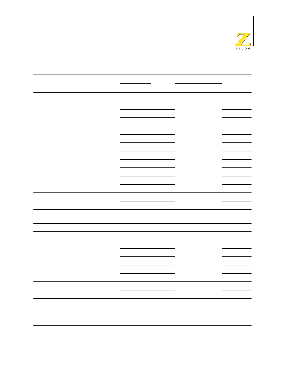
UM012811-0904
eZ8 CPU Instruction Set Summary
eZ8 CPU
User Manual
48
LDX dst, src
dst
src
r
ER
84
-
-
-
-
-
-
3
2
Ir
ER
85
3
3
R
IRR
86
3
4
IR
IRR
87
3
5
r
X(rr)
88
3
4
X(rr)
r
89
3
4
ER
r
94
3
2
ER
Ir
95
3
3
IRR
R
96
3
4
IRR
IR
97
3
5
ER
ER
E8
4
2
ER
IM
E9
4
2
LEA dst, X(src)
dst
src + X
r
X(r)
98
-
-
-
-
-
-
3
3
rr
X(rr)
99
3
5
MULT dst
dst[15:0]
dst[15:8] * dst[7:0]
RR
F4
-
-
-
-
-
-
2
8
NOP
No operation
0F
-
-
-
-
-
-
1
2
OR dst, src
dst
dst OR src
r
r
42
-
*
*
0
-
-
2
3
r
Ir
43
2
4
R
R
44
3
3
R
IR
45
3
4
R
IM
46
3
3
IR
IM
47
3
4
ORX dst, src
dst
dst OR src
ER
ER
48
-
*
*
0
-
-
4
3
ER
IM
49
4
3
Table 20. eZ8 CPU Instruction Summary (Continued)
Assembly
Mnemonic
Symbolic Operation
Address Mode
Opcode(s)
(Hex)
Flags
Fetch
Cycles
Instr.
Cycles
dst
src
C Z S
V D H
Flags Notation:
* = Value is a function of the result of the operation.
- = Unaffected
X = Undefined
C = Carry Flag
0 = Reset to 0
1 = Set to 1
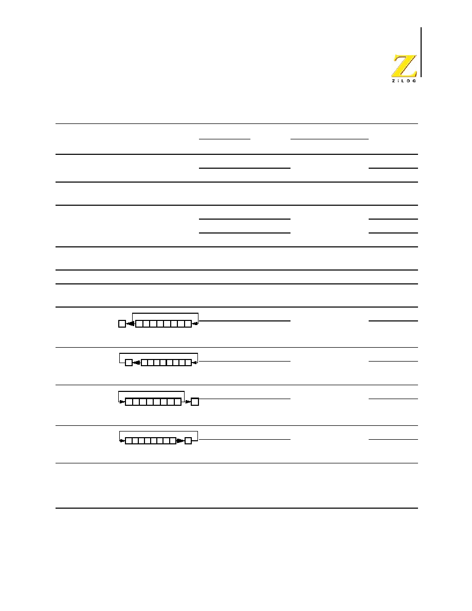
UM012811-0904
eZ8 CPU Instruction Set Summary
eZ8 CPU
User Manual
49
POP dst
dst
@SP
SP
SP + 1
R
50
-
-
-
-
-
-
2
2
IR
51
2
3
POPX dst
dst
@SP
SP
SP + 1
ER
D8
-
-
-
-
-
-
3
2
PUSH src
SP
SP � 1
@SP
src
R
70
-
-
-
-
-
-
2
2
IR
71
2
3
IM
1F70
3
2
PUSHX src
SP
SP � 1
@SP
src
ER
C8
-
-
-
-
-
-
3
2
RCF
C
0
CF
0
-
-
-
-
-
1
2
RET
PC
@SP
SP
SP + 2
AF
-
-
-
-
-
-
1
4
RL dst
R
90
*
*
*
*
-
-
2
2
IR
91
2
3
RLC dst
R
10
*
*
*
*
-
-
2
2
IR
11
2
3
RR dst
R
E0
*
*
*
*
-
-
2
2
IR
E1
2
3
RRC dst
R
C0
*
*
*
*
-
-
2
2
IR
C1
2
3
Table 20. eZ8 CPU Instruction Summary (Continued)
Assembly
Mnemonic
Symbolic Operation
Address Mode
Opcode(s)
(Hex)
Flags
Fetch
Cycles
Instr.
Cycles
dst
src
C Z S
V D H
Flags Notation:
* = Value is a function of the result of the operation.
- = Unaffected
X = Undefined
C = Carry Flag
0 = Reset to 0
1 = Set to 1
D7 D6 D5 D4 D3 D2 D1 D0
dst
C
D7 D6 D5 D4 D3 D2 D1 D0
dst
C
D7 D6 D5 D4 D3 D2 D1 D0
dst
C
D7 D6 D5 D4 D3 D2 D1 D0
dst
C
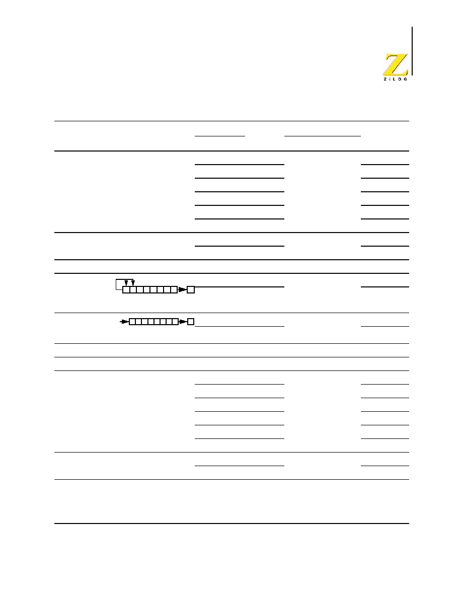
UM012811-0904
eZ8 CPU Instruction Set Summary
eZ8 CPU
User Manual
50
SBC dst, src
dst
dst � src - C
r
r
32
*
*
*
*
1
*
2
3
r
Ir
33
2
4
R
R
34
3
3
R
IR
35
3
4
R
IM
36
3
3
IR
IM
37
3
4
SBCX dst, src
dst
dst � src - C
ER
ER
38
*
*
*
*
1
*
4
3
ER
IM
39
4
3
SCF
C
1
DF
1
-
-
-
-
-
1
2
SRA dst
R
D0
*
*
*
0
-
-
2
2
IR
D1
2
3
SRL dst
R
1F C0
*
*
0
*
-
-
3
2
IR
1F C1
3
3
SRP src
RP
src
IM
01
-
-
-
-
-
-
2
2
STOP
Stop Mode
6F
-
-
-
-
-
-
1
2
SUB dst, src
dst
dst � src
r
r
22
*
*
*
*
1
*
2
3
r
Ir
23
2
4
R
R
24
3
3
R
IR
25
3
4
R
IM
26
3
3
IR
IM
27
3
4
SUBX dst, src
dst
dst � src
ER
ER
28
*
*
*
*
1
*
4
3
ER
IM
29
4
3
Table 20. eZ8 CPU Instruction Summary (Continued)
Assembly
Mnemonic
Symbolic Operation
Address Mode
Opcode(s)
(Hex)
Flags
Fetch
Cycles
Instr.
Cycles
dst
src
C Z S
V D H
Flags Notation:
* = Value is a function of the result of the operation.
- = Unaffected
X = Undefined
C = Carry Flag
0 = Reset to 0
1 = Set to 1
D7 D6 D5 D4 D3 D2 D1 D0
dst
C
D7 D6 D5 D4 D3 D2 D1 D0
dst
C
0

UM012811-0904
eZ8 CPU Instruction Set Summary
eZ8 CPU
User Manual
51
SWAP dst
dst[7:4]
dst[3:0]
R
F0
X *
* X
-
-
2
2
IR
F1
2
3
TCM dst, src
(NOT dst) AND src
r
r
62
-
*
*
0
-
-
2
3
r
Ir
63
2
4
R
R
64
3
3
R
IR
65
3
4
R
IM
66
3
3
IR
IM
67
3
4
TCMX dst, src
(NOT dst) AND src
ER
ER
68
-
*
*
0
-
-
4
3
ER
IM
69
4
3
TM dst, src
dst AND src
r
r
72
-
*
*
0
-
-
2
3
r
Ir
73
2
4
R
R
74
3
3
R
IR
75
3
4
R
IM
76
3
3
IR
IM
77
3
4
TMX dst, src
dst AND src
ER
ER
78
-
*
*
0
-
-
4
3
ER
IM
79
4
3
TRAP Vector
SP
SP � 2
@SP
PC
SP
SP � 1
@SP
FLAGS
PC
@Vector
Vector
F2
-
-
-
-
-
-
2
6
WDT
5F
-
-
-
-
-
-
1
2
Table 20. eZ8 CPU Instruction Summary (Continued)
Assembly
Mnemonic
Symbolic Operation
Address Mode
Opcode(s)
(Hex)
Flags
Fetch
Cycles
Instr.
Cycles
dst
src
C Z S
V D H
Flags Notation:
* = Value is a function of the result of the operation.
- = Unaffected
X = Undefined
C = Carry Flag
0 = Reset to 0
1 = Set to 1

UM012811-0904
eZ8 CPU Instruction Set Summary
eZ8 CPU
User Manual
52
XOR dst, src
dst
dst XOR src
r
r
B2
-
*
*
0
-
-
2
3
r
Ir
B3
2
4
R
R
B4
3
3
R
IR
B5
3
4
R
IM
B6
3
3
IR
IM
B7
3
4
XORX dst, src
dst
dst XOR src
ER
ER
B8
-
*
*
0
-
-
4
3
ER
IM
B9
4
3
Table 20. eZ8 CPU Instruction Summary (Continued)
Assembly
Mnemonic
Symbolic Operation
Address Mode
Opcode(s)
(Hex)
Flags
Fetch
Cycles
Instr.
Cycles
dst
src
C Z S
V D H
Flags Notation:
* = Value is a function of the result of the operation.
- = Unaffected
X = Undefined
C = Carry Flag
0 = Reset to 0
1 = Set to 1

eZ8 CPU
User Manual
UM012811-0904
eZ8 CPU Instruction Set Description
53
eZ8 CPU Instruction Set Description
The following pages provide detailed descriptions of the assembly language instructions
available with the eZ8 CPU. The instruction set available with the eZ8 CPU is a superset
of the original Z8
�
instruction set. The instruction set descriptions on the following pages
are organized alphabetically by mnemonic. Figure 19 illustrates an example layout of the
instruction pages that follow.
Mnemonic
Description
Simplified description of assembly coding
Operation
Symbolic description of the operation performed
Description
Detailed description of the instruction operation.
Flags
Information on how the CPU Flags are affected by the instruction operation.
Attributes
Table providing information on assembly coding, opcode value, and operand ordering.
Escaped Mode Addressing
Description of Escaped Mode addressing applicable to this instruction.
Example
�
A simple code example using the instruction.
Figure 19. Example Instruction Description

UM012811-0904
eZ8 CPU Instruction Set Description
eZ8 CPU
User Manual
54
ADC
Add with Carry
ADC dst, src
Operation
dst
dst + src + C
Description
The source operand and the Carry (C) flag are added to the destination operand. Two's-
complement addition is performed. The sum is stored in the destination operand. The con-
tents of the source operand are not affected. In multiple-precision (multi-byte) arithmetic,
this instruction permits the carry from the addition of low-order byte operations to be car-
ried into the addition of high-order bytes.
Flags
C
Set if there is a carry from bit 7; reset otherwise.
Z
Set if the result is zero; reset otherwise.
S
Set if the result is negative; reset otherwise.
V
Set if an arithmetic overflow occurs; reset otherwise.
D
Reset to 0.
H
Set if there is a carry from bit 3 of the result; reset otherwise.
C
Z
S
V
D
H

UM012811-0904
eZ8 CPU Instruction Set Description
eZ8 CPU
User Manual
55
Attributes
Escaped Mode Addressing
Using Escaped Mode Addressing, address modes R or IR can specify a Working Register.
If the high nibble of the source or destination address is
EH
(1110B), a Working Register is
inferred. For example, if Working Register R12 (
CH
) is the desired destination operand,
use
ECH
as the destination operand in the opcode. To access Registers with addresses
E0H
to
EFH
, either set the Working Group Pointer, RP[7:4], to
EH
or use indirect addressing.
Examples
�
If Working Register R3 contains the value
16H
, the Carry flag is 1, and Working
Register R11 contains the value
20H
, the statement:
ADC R3, R11
Object Code: 12 3B
leaves the value
37H
in Working Register R3 and clears the C, Z, S, V, D, and H flags.
�
If Working Register R15 contains the value
16H
, the Carry flag is not set, Working
Register R10 contains the value
20H
, and Register
20H
contains the value
11H
, the
statement:
ADC R15, @R10
Object Code: 13 FA
leaves the value
27H
in Working Register R15 and clears the C, Z, S, V, D, and H
flags.
�
If Register 34H contains the value
2EH
, the Carry flag is set, and Register 12H
contains the value
1BH
, the statement:
ADC 34H, 12H
Object Code: 14 12 34
leaves the value
4AH
in Register 34H, sets the H flag and clears the C, Z, S, V, and D
flags.
Mnemonic
Destination, Source
Opcode (Hex)
Operand 1
Operand 2
Operand 3
ADC
r1, r2
12
{r1, r2}
--
--
ADC
r1, @r2
13
{r1, r2}
--
--
ADC
R1, R2
14
R2
R1
--
ADC
R1, @R2
15
R2
R1
--
ADC
R1, IM
16
R1
IM
--
ADC
@R1, IM
17
R1
IM
--

UM012811-0904
eZ8 CPU Instruction Set Description
eZ8 CPU
User Manual
56
�
Using Escaped Mode Addressing, if Working Register R4 contains the value
2EH
, the
Carry flag is set, and Register 12H contains the value
1BH
, the statement:
ADC E4H, 12H
Object Code: 14 12 E4
leaves the value
4AH
in Working Register R4, sets the H flag, and clears the C, Z, S, V,
and D flags.
�
Using Escaped Mode Addressing, if Register 4BH contains the value
82H
, the Carry
flag is set, Working Register R3 contains the value
10H
, and Register 10H contains the
value
01H
, the statement:
ADC 4BH, @R3
Object Code: 15 E3 4B
leaves the value
84H
in Register 4BH, sets the S flag and clears the C, Z, V, D, and H
flags.
�
If Register 6CH contains the value
2AH
, and the Carry flag is not set, the statement:
ADC 6CH, #03H
Object Code: 16 6C 03
leaves the value
2DH
in Register 6CH and clears the C, Z, S, V, D, and H flags.
�
If Register D4H contains the value
5FH
, Register 5FH contains the value
4CH
, and the
Carry flag is set, the statement:
ADC @D4H, #02H
Object Code: 17 D4 02
leaves the value
4FH
in Register 5FH and clears the C, Z, S, V, D, and H flags.

UM012811-0904
eZ8 CPU Instruction Set Description
eZ8 CPU
User Manual
57
ADCX
Add with Carry using Extended Addressing
ADCX dst, src
Operation
dst
dst + src + C
Description
Add the source operand and the Carry (C) flag to the destination operand. Perform two's-
complement addition. Store the sum in the destination operand. The contents of the source
operand are not affected. In multiple-precision (multi-byte) arithmetic, this instruction
permits the carry from the addition of low-order byte operations to be carried into the
addition of high-order bytes. The destination and source operands use 12-bit addresses to
access any address in the Register File.
Flags
Attributes
Escaped Mode Addressing
Using Escaped Mode Addressing, address mode ER for the source or destination can spec-
ify a Working Register with 4-bit addressing.
If the high byte of the source or destination address is
EEH
(11101110B), a Working Regis-
ter is inferred. For example, the operand
EE3H
selects Working Register R3. The full 12-
bit address is given by {RP[3:0], RP[7:4], 3H}.
To access Registers on Page EH (addresses
E00H
to
EFFH
), set the Page Pointer, RP[3:0],
to
EH
and set the Working Group Pointer, RP[7:4], to the desired Working Group.
C
Set if there is a carry from bit 7; reset otherwise.
Z
Set if the result is zero; reset otherwise.
S
Set if the result is negative; reset otherwise.
V
Set if an arithmetic overflow occurs; reset otherwise.
D
Reset to 0.
H
Set if there is a carry from bit 3 of the result; reset otherwise.
Mnemonic Destination, Source
Opcode (Hex)
Operand 1
Operand 2
Operand 3
ADCX
ER1, ER2
18
ER2[11:4]
{ER2[3:0], ER1[11:8]} ER1[7:0]
ADCX
ER1, IM
19
IM
{0H, ER1[11:8]}
ER1[7:0]

UM012811-0904
eZ8 CPU Instruction Set Description
eZ8 CPU
User Manual
58
Examples
�
If Register 634H contains the value
2EH
, the Carry flag is set, and Register B12H
contains the value
1BH
, the statement:
ADCX 634H, B12H
Object Code: 18 B1 26 34
leaves the value
4AH
in Register 634H, sets the H flag and clears the C, Z, S, V, and D
flags.
Using Escaped Mode Addressing, if Working Register R4 contains the value
2EH
, the
Carry flag is set, and Register B12H contains the value
1BH
, the statement:
ADCX EE4H, B12H
Object Code: 18 B1 2E E4
leaves the value
4AH
in Working Register R4, sets the H flag and clears the C, Z, S, V,
and D flags.
�
If Register 46CH contains the value
2AH
, and the Carry flag is not set, the statement:
ADCX 46CH, #03H
Object Code: 19 03 04 6C
leaves the value
2DH
in Register 46CH and clears the C, Z, S, V, D, and H flags.

UM012811-0904
eZ8 CPU Instruction Set Description
eZ8 CPU
User Manual
59
ADD
Add
ADD dst, src
Operation
dst
dst + src
Description
Add the source operand to the destination operand. Perform two's-complement addition.
Store the sum in the destination operand. The contents of the source operand are not
affected.
Flags
Attributes
Escaped Mode Addressing
Using Escaped Mode Addressing, address modes R or IR can specify a Working Register.
If the high nibble of the source or destination address is
EH
(1110B), a Working Register is
inferred. For example, if Working Register R12 (
CH
) is the desired destination operand,
use
ECH
as the destination operand in the opcode. To access Registers with addresses
E0H
to E
FH
, either set the Working Group Pointer, RP[7:4], to
EH
or use indirect addressing.
C
Set if there is a carry from bit 7; reset otherwise.
Z
Set if the result is zero; reset otherwise.
S
Set if the result is negative; reset otherwise.
V
Set if an arithmetic overflow occurs; reset otherwise.
D
Reset to 0.
H
Set if there is a carry from bit 3 of the result; reset otherwise.
Mnemonic
Destination, Source
Opcode (Hex)
Operand 1
Operand 2
Operand 3
ADD
r1, r2
02
{r1, r2}
--
--
ADD
r1, @r2
03
{r1, r2}
--
--
ADD
R1, R2
04
R2
R1
--
ADD
R1, @R2
05
R2
R1
--
ADD
R1, IM
06
R1
IM
--
ADD
@R1, IM
07
R1
IM
--

UM012811-0904
eZ8 CPU Instruction Set Description
eZ8 CPU
User Manual
60
Examples
�
If Working Register R3 contains the value
16H
and Working Register R11 contains the
value
20H
, the statement:
ADD R3, R11
Object Code: 02 3B
leaves the value
36H
in Working Register R3 and clears the C, Z, S, V, D, and H flags.
�
If Working Register R15 contains the value
16H
, Working Register R10 contains
20H
,
and Register 20H contains the value
11H
, the statement:
ADD R15, @R10
Object Code: 03 FA
leaves the value
27H
in Working Register R15 and clears the C, Z, S, V, D, and H
flags.
�
If Register 34H contains the value
2EH
and Register 12H contains the value
1BH
, the
statement:
ADD 34H, 12H
Object Code: 04 12 34
leaves the value
49H
in Register 34H, sets the H flag and clears the C, Z, S, V, and D
flags.
�
Using Escaped Mode Addressing, if Register 4BH contains the value
82H
, Working
Register R3 contains the value
10H
, and Register 10H contains the value
01H
, the
statement:
ADD 4BH, @R3
Object Code: 05 E3 4B
leaves the value 83H in Register 4BH, sets the S flag and clears the C, Z, V, D, and H
flags.
�
If Register 6CH contains the value
2AH
, the statement:
ADD 6CH, #03H
Object Code: 06 6C 03
leaves the value
2DH
in Register 6H. The C, Z, S, V, D, and H flags clear.
�
If Register D4H contains the value
5FH
and Register 5FH contains the value
4CH
, the
statement:
ADD @D4H, #02H
Object Code: 07 D4 02
leaves the value
4EH
in Register 5FH and clears
the
C, Z, S, V, D, and H flags.

UM012811-0904
eZ8 CPU Instruction Set Description
eZ8 CPU
User Manual
61
ADDX
Add using Extended Addressing
ADDX dst, src
Operation
dst
dst + src
Description
The source operand is added to the destination operand. Two's-complement addition is
performed. The sum is stored in the destination operand. The contents of the source oper-
and are not affected.
Flags
Attributes
Escaped Mode Addressing
Using Escaped Mode Addressing, address mode ER for the source or destination specifies
a Working Register with 4-bit addressing.
If the high byte of the source or destination address is
EEH
(11101110B), a Working Regis-
ter is inferred. For example, the operand EE3H selects Working Register R3. The full 12-
bit address is given by {RP[3:0], RP[7:4], 3H}.
To access Registers on Page EH (addresses
E00H
to
EFFH
), set the Page Pointer, RP[3:0],
to EH and set the Working Group Pointer, RP[7:4], to the desired Working Group.
C
Set if there is a carry from bit 7; reset otherwise.
Z
Set if the result is zero; reset otherwise.
S
Set if the result is negative; reset otherwise.
V
Set if an arithmetic overflow occurs; reset otherwise.
D
Reset to 0.
H
Set if there is a carry from bit 3 of the result; reset otherwise.
Mnemonic Destination, Source
Opcode (Hex)
Operand 1
Operand 2
Operand 3
ADDX
ER1, ER2
08
ER2[11:4]
{ER2[3:0], ER1[11:8]} ER1[7:0]
ADDX
ER1, IM
09
IM
{0H, ER1[11:8]}
ER1[7:0]

UM012811-0904
eZ8 CPU Instruction Set Description
eZ8 CPU
User Manual
62
Examples
�
If Register 634H contains the value
2EH
and Register B12H contains the value
1BH
,
the statement:
ADDX 634H, B12H
Object Code: 08 B1 26 34
leaves the value
49H
in Register 634H, sets the H flag and clears the C, Z, S, V, and D
flags.
�
Using Escaped Mode Addressing, if Working Register R4 contains the value
2EH
and
Register B12H contains the value
1BH
, the statement:
ADDX EE4H, B12H
Object Code: 08 B1 2E E4
leaves the value
49H
in Working Register R4, sets the H flag and clears the C, Z, S, V,
and D flags.
�
If Register 46CH contains the value
2AH
the statement:
ADDX 46CH, #03H
Object Code: 09 03 04 6C
leaves the value 2DH in Register 46CH and clears the C, Z, S, V, D, and H flags.

UM012811-0904
eZ8 CPU Instruction Set Description
eZ8 CPU
User Manual
63
AND
Logical AND
AND dst, src
Operation
dst
dst AND src
Description
The source operand is logically AND'ed with the destination operand. An AND operation
stores a 1 when the corresponding bits in the two operands are both 1; otherwise the oper-
ation stores a 0. The destination operand stores the result. The contents of the source bit
are unaffected.
Flags
Attributes
Escaped Mode Addressing
Using Escaped Mode Addressing, address modes R or IR specify a Working Register. If
the high nibble of the source or destination address is
EH
(1110B), a Working Register is
inferred. For example, if Working Register R12 (
CH
) is the desired destination operand,
use
ECH
as the destination operand in the opcode. To access Registers with addresses
E0H
to
EFH
, either set the Working Group Pointer, RP[7:4], to
EH
or use indirect addressing.
C
Unaffected.
Z
Set if the result is zero; reset otherwise.
S
Set if Bit 7 of the result is set; reset otherwise.
V
Reset to 0.
D
Unaffected.
H
Unaffected.
Mnemonic
Destination, Source
Opcode (Hex)
Operand 1
Operand 2
Operand 3
AND
r1, r2
52
{r1, r2}
--
--
AND
r1, @r2
53
{r1, r2}
--
--
AND
R1, R2
54
R2
R1
--
AND
R1, @R2
55
R2
R1
--
AND
R1, IM
56
R1
IM
--
AND
@R1, IM
57
R1
IM
--

UM012811-0904
eZ8 CPU Instruction Set Description
eZ8 CPU
User Manual
64
Examples
�
If Working Register R1 contains the value
38H
(00111000B) and Working Register
R14 contains the value
8DH
(10001101B), the statement:
AND R1, R14
Object Code: 52 1E
leaves the value
08H
(00001000B)
in Working Register R1 and clears the Z, V, and S
flags.
�
If Working Register R4 contains the value
F9H
(11111001B), Working Register R13
contains the value
7BH
, and Register 7BH contains the value
6AH
(01101010B), the
statement:
AND R4, @R13
Object Code: 53 4D
leaves the value
68H
(01101000B) in Working Register R4 and clears the Z, V, and S
flags.
�
If Register 3AH contains the value
F5H
(11110101B) and Register
42H
contains the
value
0AH
(00001010), the statement:
AND 3AH, 42H
Object Code: 54 42 3A
leaves the value
00H
(00000000B) in Register 3AH, sets the Z flag and clears the V
and S flags.
�
Using Escaped Mode Addressing, if Working Register R5 contains the value
F0H
(11110000B), Register 45H contains the value
3AH
, and Register 3AH contains the
value
7FH
(01111111B), the statement:
AND R5, @45H
Object Code: 55 45 E5
leaves the value
70H
(01110000B) in Working Register R5 and clears the Z, V, and S
flags.
�
If Register 7AH contains the value
F7H
(11110111B), the statement:
AND 7AH, #F0H
Object Code: 56 7A F0
leaves the value
F0H
(11110000B) in Register 7AH, sets the S flag is set and clears the
Z and V flags.
�
Using Escaped Mode Addressing, if Working Register R3 contains the value
3EH
and
Register 3EH contains the value
ECH
(11101100B), the statement:
AND @R3, #05H
Object Code: 57 E3 05

UM012811-0904
eZ8 CPU Instruction Set Description
eZ8 CPU
User Manual
65
leaves the value
04H
(00000100B) in Register 3EH and clears the Z, V, and S flags.

UM012811-0904
eZ8 CPU Instruction Set Description
eZ8 CPU
User Manual
66
ANDX
Logical AND using Extended Addressing
ANDX dst, src
Operation
dst
dst AND src
Description
The source operand is AND'ed with the destination operand. An AND operation stores a 1
when the corresponding bits in the two operands are both 1; otherwise this operation stores
a 0. The destination operand stores the result. The contents of the source operand are unaf-
fected.
Flags
Attributes
Escaped Mode Addressing
Using Escaped Mode Addressing, address mode ER for the source or destination can spec-
ify a Working Register with 4-bit addressing.
If the high byte of the source or destination address is
EEH
(11101110B), a Working Regis-
ter is inferred. For example, the operand EE3H selects Working Register R3. The full 12-
bit address is given by {RP[3:0], RP[7:4], 3H}.
To access Registers on Page EH (addresses E00H to EFFH), set the Page Pointer, RP[3:0],
to
EH
and set the Working Group Pointer, RP[7:4], to the desired Working Group.
C
Unaffected.
Z
Set if the result is zero; reset otherwise.
S
Set if the result is negative; reset otherwise.
V
Reset to 0.
D
Unaffected.
H
Unaffected.
Mnemonic Destination, Source
Opcode (Hex)
Operand 1
Operand 2
Operand 3
ANDX
ER1, ER2
58
ER2[11:4]
{ER2[3:0], ER1[11:8]} ER1[7:0]
ANDX
ER1, IM
59
IM
{0H, ER1[11:8]}
ER1[7:0]

UM012811-0904
eZ8 CPU Instruction Set Description
eZ8 CPU
User Manual
67
Examples
�
If Register 93AH contains the value F5H (11110101B) and Register
142H
contains the
value
0AH
(00001010), the statement:
ANDX 93AH, 142H
Object Code: 58 14 29 3A
leaves the value
00H
(00000000B) in Register 93AH, sets the Z flag, and the V and S
flags clear.
�
If Register D7AH contains the value
F7H
(11110111B), the statement:
ANDX D7AH, #F0H
Object Code: 59 F0 0D 7A
leaves the value
F0H
(11110000B) in Register 7AH, sets the S flag and clears the Z
and V flags.

UM012811-0904
eZ8 CPU Instruction Set Description
eZ8 CPU
User Manual
68
ATM
Atomic Execution
ATM
Operation
Blocks all interrupt and DMA requests during execution of the next 3instructions.
Description
The Atomic instruction forces the eZ8 CPU to execute the next 3 instructions as a single
block (i.e. atom) of operations. During execution of these next 3 instructions, all interrupts
and DMA requests are prevented. This allows operations to be performed on multi-byte
registers and memory locations that could be changed or used by interrupts or the DMA.
One example of potential use of the ATM instruction is during adjustment of the multi-
byte stack pointer value.
Flags
Attributes
C
Unaffected.
Z
Unaffected.
S
Unaffected.
V
Unaffected.
D
Unaffected.
H
Unaffected.
MIE
Unaffected.
Mnemonic Destination, Source
Byte 1
Byte 2
Byte 3
Byte 4
ATM
--
2F
--
--
--

UM012811-0904
eZ8 CPU Instruction Set Description
eZ8 CPU
User Manual
69
BCLR
Bit Clear
BCLR bit, dst
Operation
dst[bit]
0
Description
The selected bit in the destination operand is 0. All other bits are unaffected.
Flags
Attributes
Example
�
If Working Register R7 contains the value
38H
(00111000B), the statement:
BCLR 4, R7
Object Code: E2 47
leaves the value
28H
(00101000B)
in Working Register R7 and clears the V flag.
C
Unaffected.
Z
Set if the result is zero; reset otherwise.
S
Set if the result is negative; reset otherwise.
V
Reset to 0.
D
Unaffected.
H
Unaffected.
Mnemonic
Bit, Destination
Opcode (Hex)
Operand 1
Operand 2
Operand 3
BCLR
bit, r1
E2
{0B, bit, r1}
--
--

UM012811-0904
eZ8 CPU Instruction Set Description
eZ8 CPU
User Manual
70
BIT
Bit Set/Reset
BIT p, bit, dst
Operation
dst[bit]
p
Description
The selected bit in the destination operand is the binary value p (0 or 1). All other bits are
unaffected.
Flags
Attributes
Example
�
If Working Register R7 contains the value
38H
(00111000B), the statement:
BIT 0, 4, R7
Object Code: E2 47
leaves the value
28H
(00101000B)
in Working Register R7 and clears the V flag.
�
If Working Register R7 contains the value
38H
(00111000B), the statement:
BIT 1, 2, R7
Object Code: E2 A7
leaves the value
3AH
(00111010B)
in Working Register R7 and clears the V flag.
C
Unaffected.
Z
Set if the result is zero; reset otherwise.
S
Set if the result is negative; reset otherwise.
V
Reset to 0.
D
Unaffected.
H
Unaffected.
Mnemonic
Polarity, Bit,
Destination Opcode
(Hex)
Operand 1
Operand 2
Operand 3
BIT
p, bit, r1
E2
{p, bit, r1}
--
--

UM012811-0904
eZ8 CPU Instruction Set Description
eZ8 CPU
User Manual
71
BRK
On-Chip Debugger Break
BRK
Operation
None.
Description
Executes a on-chip debugger break at this address. Refer to the device-specific Product
Specification for information regarding the on-chip debugger.
Flags
Attributes
C
Unaffected.
Z
Unaffected.
S
Unaffected.
V
Unaffected.
D
Unaffected.
H
Unaffected.
Mnemonic
Destination, Source
Opcode (Hex)
Operand 1
Operand 2
Operand 3
BRK
--
00
--
--
--

UM012811-0904
eZ8 CPU Instruction Set Description
eZ8 CPU
User Manual
72
BSET
Bit Set
BSET bit, dst
Operation
dst[bit]
1
Description
The selected bit in the destination operand is set to 1. All other bits are unaffected.
Flags
Attributes
Example
�
If Working Register R7 contains the value
38H
(00111000B), the statement:
BSET 2, R7
Object Code: E2 A7
leaves the value
3CH
(00111010B)
in Working Register R7 and clears the V flag.
C
Unaffected.
Z
Set if the result is zero; reset otherwise.
S
Set if the result is negative; reset otherwise.
V
Reset to 0.
D
Unaffected.
H
Unaffected.
Mnemonic
Bit, Destination
Opcode (Hex)
Operand 1
Operand 2
Operand 3
BSET
bit, r1
E2
{1B, bit, r1}
--
--

UM012811-0904
eZ8 CPU Instruction Set Description
eZ8 CPU
User Manual
73
BSWAP
Bit Swap
BSWAP dst
Operation
dst[7:0]
dst[0:7]
Description
The contents of the Register are bit flipped:
dst[7] <--> dst[0]
dst[6] <--> dst[1]
dst[5] <--> dst[2]
dst[4] <--> dst[3]
Flags
Attributes
Escaped Mode Addressing
Using Escaped Mode Addressing, address mode R specifies a Working Register. If the
destination address is prefixed by
EH
(1110B), a Working Register is inferred. For exam-
ple, if Working Register R12 (
CH
) is the desired destination operand, use
ECH
as the desti-
nation operand in the opcode. To access Registers with addresses
E0H
to
EFH
, either set
the Working Group Pointer, RP[7:4], to
EH
or use indirect addressing.
Example
�
If Register 27H contains the value
53H
(01010011B), the statement:
BSWAP 27
Object Code: D5 27
C
Undefined.
Z
Set if the result is zero; reset otherwise.
S
Set if the result is negative; reset otherwise.
V
Reset to 0.
D
Unaffected.
H
Unaffected.
Mnemonic
Destination
Opcode (Hex)
Operand 1
Operand 2
Operand 3
BSWAP
R1
D5
R1
--
--

UM012811-0904
eZ8 CPU Instruction Set Description
eZ8 CPU
User Manual
74
leaves the value
CAH
(11001010B)
in Register 27, sets the S flag and clears the V flag..
The C flag is undefined.

UM012811-0904
eZ8 CPU Instruction Set Description
eZ8 CPU
User Manual
75
BTJ
Bit Test and Jump
BTJ p, bit, src, DA
Operation
if src[bit] = p {
PC
PC + X
}
where the jump offset, X, is calculated by the eZ8 CPU assembler from the Program
Counter (PC) value and the Destination Address (DA).
Description
The selected bit in the source operand or register pointed to by the source operand is com-
pared with the p flag bit. If the bit in the source is equal to the polarity p, the signed dis-
placement (X) is added to the Program Counter, which causes a jump. The displacement
value can be from -128 to +127. This instruction tests only a single bit position. Multiple
bits cannot be tested simultaneously.
Figure 20. BTJ Operand Description
Polarity Bit (p)
Bit Position Tested
Operand[3:0]
Decimal Binary
Binary
Hexadecimal
0
0
000
0000
0
0
1
001
0001
1
0
2
010
0010
2
0
3
011
0011
3
0
4
100
0100
4
0
5
101
0101
5
0
6
110
0110
6
0
7
111
0111
7
1
0
000
1000
8
1
1
001
1001
9
1
2
010
1010
A
1
3
011
1011
B
1
4
100
1100
C
1
5
101
1101
D
1
6
110
1110
E
1
7
111
1111
F

UM012811-0904
eZ8 CPU Instruction Set Description
eZ8 CPU
User Manual
76
Flags
Attributes
Examples
�
If Working Register R7 contains the value
20H
(00100000B), the BTJ instruction that
begins the following code segment:
does not cause a Program Counter jump to occur because bit 5 of Working Register R7
fails the test for a 0. The next instruction executed after the BTJ is the HALT
instruction. The flags are unaffected.
�
If Working Register R7 contains the value
20H
(00100000B), the BTJ instruction that
begins the following code segment:
C
Unaffected.
Z
Unaffected.
S
Unaffected.
V
Unaffected.
D
Unaffected.
H
Unaffected.
Mnemonic
Polarity, Bit, Source,
Address
Opcode (Hex)
Operand 1
Operand 2
Operand 3
BTJ
p, bit, r2, DA
F6
{p, bit[2:0], r2}
X
--
BTJ
p, bit, @r2, DA
F7
{p, bit[2:0], r2}
X
--
Assembly Code
Object Code
BTJ 0, 5, r7, NEXT
F6 57 01
HALT
7F
NEXT:
This label is not assembled, but used by the assembler to identify
the destination address (the address of the next instruction).
LD r0, @r2
E3 02
Assembly Code
Object Code
BTJ 1, 5, r7, NEXT
F6 D7 01
HALT
7F

UM012811-0904
eZ8 CPU Instruction Set Description
eZ8 CPU
User Manual
77
causes a Program Counter jump to occur because bit 5 of Working Register R7 passes
the test for a 1. The next instruction executed after the BTJ is the LD instruction. The
eZ8 CPU assembler automatically calculates the desired displacement value of
01H
,
allowing the Program Counter to skip the one byte HALT instruction and jump to the
NEXT label that identifies the LD instruction address. The flags are unaffected.
NEXT:
This label is not assembled, but used by the assembler to identify
the destination address (the address of the next instruction).
LD r0, @r2
E3 02
Assembly Code
Object Code
BTJ 1, 5, r7, NEXT
F6 D7 01

UM012811-0904
eZ8 CPU Instruction Set Description
eZ8 CPU
User Manual
78
BTJNZ
Bit Test and Jump if Non-Zero
BTJNZ bit, src, DA
Operation
if src[bit] = 1 {
PC
PC + X
}
where the jump offset, X, is calculated by the eZ8 CPU assembler from the Program
Counter (PC) value and the Destination Address (DA).
Description
The selected bit in the source operand or register pointed to by the source operand is com-
pared with the a logical 1. If the selected bit is 1, the signed destination displacement (X)
is added to the Program Counter, that causes a jump. The displacement value can be from
-128 to +127. This instruction tests only a single bit position. Multiple bits cannot be
tested simultaneously.
Figure 21. BTJNZ Operand Description
Bit Position Tested
Operand[3:0]
Decimal Binary
Binary
Hexadecimal
0
000
1000
8
1
001
1001
9
2
010
1010
A
3
011
1011
B
4
100
1100
C
5
101
1101
D
6
110
1110
E
7
111
1111
F

UM012811-0904
eZ8 CPU Instruction Set Description
eZ8 CPU
User Manual
79
Flags
Attributes
Examples
�
If Working Register R7 contains the value
20H
(00100000B), the BTJNZ instruction
that begins the following code segment:
causes a Program Counter jump to occur because bit 5 of Working Register R7 passes
the test for a 1. The next instruction executed after the BTJNZ is the LD instruction.
The eZ8 CPU assembler automatically calculates the desired displacement value of
01H
, allowing the Program Counter to skip the one byte HALT instruction and jump to
the NEXT label that identifies the LD instruction address. The flags are unaffected.
�
If Working Register R7 contains the value
20H
(00100000B), the BTJNZ instruction
that begins the following code segment:
C
Unaffected.
Z
Unaffected.
S
Unaffected.
V
Unaffected.
D
Unaffected.
H
Unaffected.
Mnemonic
Bit, Source, Address Opcode (Hex)
Operand 1
Operand 2
Operand 3
BTJNZ
bit, r2, DA
F6
{1B, bit, r2}
X
--
BTJNZ
bit, @r2, DA
F7
{1B, bit, r2}
X
--
Assembly Code
Object Code
BTJNZ 5, r7, NEXT
F6 D7 01
HALT
7F
NEXT:
This label is not assembled, but used by the assembler to identify
the destination address (the address of the next instruction).
LD r0, @r2
E3 02

UM012811-0904
eZ8 CPU Instruction Set Description
eZ8 CPU
User Manual
80
does not cause a Program Counter jump to occur because bit 3 of Working Register R7
fails the test for a 1. The next instruction executed after the BTJNZ is the HALT
instruction. The flags are unaffected.
Assembly Code
Object Code
BTJNZ 3, r7, NEXT
F6 B7 01
HALT
7F
NEXT:
This label is not assembled, but used by the assembler to identify
the destination address (the address of the next instruction).
LD r0, @r2
E3 02

UM012811-0904
eZ8 CPU Instruction Set Description
eZ8 CPU
User Manual
81
BTJZ
Bit Test and Jump if Zero
BTJZ bit, src, DA
Operation
if src[bit] = 0 {
PC
PC + X
}
where the jump offset, X, is calculated by the eZ8 CPU assembler from the Program
Counter (PC) value and the Destination Address (DA).
Description
The selected bit in the source operand or register pointed to by the source operand is com-
pared with a logical 0. If the selected bit is 0, the signed destination displacement (X) is
added to the Program Counter, that causes a jump. The displacement value can be from -
128 to +127. This instruction tests only a single bit position. Multiple bits cannot be tested
simultaneously.
Figure 22. BTJZ Operand Description
Bit Position Tested
Operand[3:0]
Decimal Binary
Binary
Hexadecimal
0
000
0000
0
1
001
0001
1
2
010
0010
2
3
011
0011
3
4
100
0100
4
5
101
0101
5
6
110
0110
6
7
111
0111
7

UM012811-0904
eZ8 CPU Instruction Set Description
eZ8 CPU
User Manual
82
Flags
Attributes
Examples
�
If Working Register R7 contains the value
20H
(00100000B), the BTJZ instruction
that begins the following code segment:
causes a Program Counter jump to occur because bit 3 of Working Register R7 passes
the test for a 0. The next instruction executed after the BTJ is the LD instruction. The
CPU assembler automatically calculates the desired displacement value of
01H
to
allow the Program Counter to skip the one byte HALT instruction and jump to the
NEXT label that identifies the LD instruction address. The flags are unaffected.
�
If Working Register R7 contains the value
20H
(00100000B), the BTJZ instruction
that begins the following code segment:
C
Unaffected.
Z
Unaffected.
S
Unaffected.
V
Unaffected.
D
Unaffected.
H
Unaffected.
Mnemonic
Bit, Source, Address Opcode (Hex)
Operand 1
Operand 2
Operand 3
BTJZ
bit, r2, DA
F6
{1, bit, r2}
X
--
BTJZ
bit, @r2, DA
F7
{1, bit, r2}
X
--
Assembly Code
Object Code
BTJZ 3, r7, NEXT
F6 37 01
HALT
7F
NEXT:
This label is not assembled, but used by the assembler to identify
the destination address (the address of the next instruction).
LD r0, @r2
E3 02

UM012811-0904
eZ8 CPU Instruction Set Description
eZ8 CPU
User Manual
83
does not cause a Program Counter jump to occur because bit 5 of Working Register R7
fails the test for a 0. The next instruction executed after the BTJZ is the HALT
instruction. The flags are unaffected.
Assembly Code
Object Code
BTJZ 5, r7, NEXT
F6 57 01
HALT
7F
NEXT:
This label is not assembled, but used by the assembler to identify
the destination address (the address of the next instruction).
LD r0, @r2
E3 02

UM012811-0904
eZ8 CPU Instruction Set Description
eZ8 CPU
User Manual
84
CALL
CALL Procedure
CALL dst
Operation
SP
SP - 2
@SP
PC
PC
dst
Description
The Stack Pointer decrements by two, the current contents of the Program Counter, which
is the address of the first instruction following the CALL instruction, are pushed onto the
top of the stack and the specified destination address is then loaded into the Program
Counter. The Program Counter now points to the first instruction of the procedure.
At the end of the procedure, a RET instruction returns to the original program flow. RET
pops the top of the stack and replaces the original value into the Program Counter.
Flags
Attributes
Escaped Mode Addressing
Using Escaped Mode Addressing, address mode IR specifies a Working Register. If the
destination address is prefixed by
EH
(1110B), a Working Register is inferred. For exam-
ple, if Working Register R12 (
CH
) is the desired destination operand, use
ECH
as the desti-
nation operand in the opcode. To access Registers with addresses
E0H
to
EFH
, either set
the Working Group Pointer, RP[7:4], to
EH
or use indirect addressing.
C
Unaffected.
Z
Unaffected.
S
Unaffected.
V
Unaffected.
D
Unaffected.
H
Unaffected.
Mnemonic
Destination
Opcode (Hex)
Operand 1
Operand 2
Operand 3
CALL
@RR1
D4
RR1
--
--
CALL
DA
D6
DA[15:8]
DA[7:0]
--

UM012811-0904
eZ8 CPU Instruction Set Description
eZ8 CPU
User Manual
85
Examples
�
If the contents of the Program Counter are
1A47H
and the contents of the Stack
Pointer are
3002H
, the statement:
CALL 3521H
Object Code: D6 35 21
causes the Stack Pointer to be decremented to
3000H
,
1A4AH
(the address following
the CALL instruction) to be stored in Program Memory locations
3001H
and
3000H
,
and the Program Counter to be loaded with
3521H
. The Program Counter now points
to the address of the first statement in the called procedure to be executed. The flags
are unaffected.
�
If the contents of the Program Counter are
1A47H
and the contents of the Stack
Pointer are
3724H
, the contents of Register A4H are
34H
, and the contents of the
Register Pair 34H are
3521H
, the statement:
CALL @A4H
Object Code: D4 A4
causes the Stack Pointer to decrement to
3722H
, stores
1A4AH
(the address following
the CALL instruction) in Program Memory locations 3723H and 3722H, and loads the
Program Counter with
3521H
. The Program Counter now points to the address of the
first statement in the called procedure to be executed. The flags are unaffected.

UM012811-0904
eZ8 CPU Instruction Set Description
eZ8 CPU
User Manual
86
CCF
Complement Carry Flag
CCF
Operation
C
~C
Description
The Carry (C) flag is complemented. If C = 1, it is 0. If C = 0, it is 1.
Flags
Attributes
Example
If the Carry flag contains a 0, the statement:
CCF
Object Code: EF
sets the Carry flag to 1.
C
Complemented.
Z
Unaffected.
S
Unaffected.
V
Unaffected.
D
Unaffected.
H
Unaffected.
Mnemonic
Destination, Source
Opcode (Hex)
Operand 1
Operand 2
Operand 3
CCF
--
EF
--
--
--

UM012811-0904
eZ8 CPU Instruction Set Description
eZ8 CPU
User Manual
87
CLR
Clear
CLR dst
Operation
dst
00H
Description
The destination operand is cleared to 00H.
Flags
Attributes
Escaped Mode Addressing
Using Escaped Mode Addressing, address modes R or IR can specify a Working Register.
If the destination address is prefixed by
EH
(1110B), a Working Register is inferred. For
example, if Working Register R12 (
CH
) is the desired destination operand, use
ECH
as the
destination operand in the opcode. To access Registers with addresses
E0H
to
EFH
, either
set the Working Group Pointer, RP[7:4], to
EH
or use indirect addressing.
Examples
�
Using Escaped Mode Addressing, if Working Register R6 contains
AFH
, the
statement:
CLR R6
Object Code: B0 E6
leaves the value
00H
in Working Register R6.
C
Unaffected.
Z
Unaffected.
S
Unaffected.
V
Unaffected.
D
Unaffected.
H
Unaffected.
Mnemonic
Destination
Opcode (Hex)
Operand 1
Operand 2
Operand 3
CLR
R1
B0
R1
--
--
CLR
@R1
B1
R1
--
--

UM012811-0904
eZ8 CPU Instruction Set Description
eZ8 CPU
User Manual
88
�
If Register A5H contains the value
23H
, and Register 23H contains the value
FCH
, the
statement:
CLR @A5H
Object Code: B1 A5
leaves the value
00H
in Register 23H.

UM012811-0904
eZ8 CPU Instruction Set Description
eZ8 CPU
User Manual
89
COM
Complement
COM dst
Operation
dst
~dst
Description
The contents of the destination operand are complemented (one's complement). All 1 bits
are changed to 0 and all 0 bits are changed to 1.
Flags
Attributes
Escaped Mode Addressing
Using Escaped Mode Addressing, address modes R or IR can specify a Working Register.
If the destination address is prefixed by
EH
(1110B), a Working Register is inferred. For
example, if Working Register R12 (
CH
) is the desired destination operand, use
ECH
as the
destination operand in the opcode. To access Registers with addresses
E0H
to
EFH
, either
set the Working Group Pointer, RP[7:4], to
EH
or use indirect addressing.
Examples
�
If Register 08H contains
24H
(00100100B), the statement:
COM 08H
Object Code: 60 08
leaves the value
DBH
(11011011B) in Register 08H, sets the S flag and clears the Z and
V flags.
C
Unaffected.
Z
Set if the result is zero; reset otherwise.
S
Set if Bit 7 of the result is set; reset otherwise.
V
Reset to 0.
D
Unaffected.
H
Unaffected.
Mnemonic
Destination
Opcode (Hex)
Operand 1
Operand 2
Operand 3
COM
R1
60
R1
--
--
COM
@R1
61
R1
--
--

UM012811-0904
eZ8 CPU Instruction Set Description
eZ8 CPU
User Manual
90
�
If Register 08H contains the value
24H
, and Register 24H contains the value
FFH
(11111111B), the statement:
COM @08H
Object Code: 61 08
leaves the value
00H
(00000000B) in Register 24H, sets the Z flag is set and clears the
V and S flags.

UM012811-0904
eZ8 CPU Instruction Set Description
eZ8 CPU
User Manual
91
CP
Compare
CP dst, src
Operation
dst - src
Description
The source operand is compared to (subtracted from) the destination operand and the flags
are set according to the results of the operation. The contents of both the source and desti-
nation operands are unaffected.
Flags
Attributes
Escaped Mode Addressing
Using Escaped Mode Addressing, address modes R or IR specify a Working Register. If
the high nibble of the source or destination address is
EH
(1110B), a Working Register is
inferred. For example, if Working Register R12 (
CH
) is the desired destination operand,
use
ECH
as the destination operand in the opcode. To access Registers with addresses
E0H
to
EFH
, either set the Working Group Pointer, RP[7:4], to
EH
or use indirect addressing.
C
Set if a borrow is required by bit 7; reset otherwise.
Z
Set if the result is zero; reset otherwise.
S
Set if Bit 7 of the result is set; reset otherwise.
V
Set if an arithmetic overflow occurs; reset otherwise.
D
Unaffected.
H
Unaffected.
Mnemonic
Destination, Source
Opcode (Hex)
Operand 1
Operand 2
Operand 3
CP
r1, r2
A2
{r1, r2}
--
--
CP
r1, @r2
A3
{r1, r2}
--
--
CP
R1, R2
A4
R2
R1
--
CP
R1, @R2
A5
R2
R1
--
CP
R1, IM
A6
R1
IM
--
CP
@R1, IM
A7
R1
IM
--

UM012811-0904
eZ8 CPU Instruction Set Description
eZ8 CPU
User Manual
92
Examples
�
If Working Register R3 contains the value
16H
and Working Register R11 contains the
value
20H
, the statement:
CP R3, R11
Object Code: A2 3B
sets the C and S flags, and clears the Z and V flags.
�
If Working Register R15 contains the value
16H
, Working Register R10 contains the
value
20H
, and Register 20H contains
11H
, the statement:
CP R15, @R10
Object Code: A3 FA
clears the C, Z, S, and V flags.
�
If Register 34H contains the value
2EH
and Register 12H contains the value
1BH
, the
statement:
CP 34H,12H
Object Code: A4 12 34
clears the C, Z, S, and V flags.
�
If Register 4BH contains the value
82H
, Working Register R3 contains the value
10H
,
and Register 10H contains the value
01H
, the statement:
CP 4BH, @R3
Object Code: A5 E3 4B
sets the S flag, and clears the C, Z, and V flags.
�
If Register 6CH contains the value
2AH
, the statement:
CP 6CH, #2AH
Object Code: A6 6C 2A
sets the Z flag, and clears the C, S, and V flags.
�
If Register D4H contains the value
FCH
, and Register FCH contains the value
8FH
, the
statement:
CP @D4H, #FFH
Object Code: A7 D4 FF
sets the V flag, and clears the C, Z, and S flags.

UM012811-0904
eZ8 CPU Instruction Set Description
eZ8 CPU
User Manual
93
CPC
Compare with Carry
CPC dst, src
Operation
dst - src - C
Description
The source operand with the C bit is compared to (subtracted from) the destination oper-
and. The contents of both operands are unaffected. For multi-precision operation, repeat-
ing this instruction enables multi-byte compares. The Zero flag is set only if the initial
state of the Zero flag is 1 and the result of the compare is 0.
Flags
Attributes
Escaped Mode Addressing
Using Escaped Mode Addressing, address modes R or IR can specify a Working Register.
If the high nibble of the source or destination address is
EH
(1110B), a Working Register is
inferred. For example, if Working Register R12 (
CH
) is the desired destination operand,
use
ECH
as the destination operand in the opcode. To access Registers with addresses
E0H
to
EFH
, either set the Working Group Pointer, RP[7:4], to
EH
or use indirect addressing.S
C
Set if a borrow is required by bit 7; reset otherwise.
Z
Set if the result is zero and the initial Zero flag is 1; reset otherwise.
S
Set if the result is negative; reset otherwise.
V
Set if an arithmetic overflow occurs; reset otherwise.
D
Unaffected.
H
Unaffected.
Mnemonic
Destination, Source
Opcode (Hex)
Operand 1
Operand 2
Operand 3
CPC
r1, r2
1F A2
{r1, r2}
--
--
CPC
r1, @r2
1F A3
{r1, r2}
--
--
CPC
R1, R2
1F A4
R2
R1
--
CPC
R1, @R2
1F A5
R2
R1
--
CPC
R1, IM
1F A6
R1
IM
--
CPC
@R1, IM
1F A7
R1
IM
--

UM012811-0904
eZ8 CPU Instruction Set Description
eZ8 CPU
User Manual
94
Examples
�
If Working Register R3 contains the value
16H
, Working Register R11 contains the
value
20H
and the Carry flag is 1, the statement:
CPC R3, R11
Object Code: 1F A2 3B
sets the C and S flags, and clears the Z and V flags.
�
If Working Register R15 contains the value
16H
, Working Register R10 contains the
value
20H
, Register 20H contains the value
11H
and the Carry flag is 0, the statement:
CPC R15, @R10
Object Code: 1F A3 FA
clears the C, Z, S, and V flags.
�
If Register 34H contains the value
2EH
and Register 12H contains the value
1BH
, and
the Carry Flag is 1, the statement:
CPC 34H,12H
Object Code: 1F A4 12 34
clears the C, Z, S, and V flags.
�
If Register 4BH contains the value
82H
, Working Register R3 contains the value
10H
,
Register 10H contains the value
81H
, the Carry flag is 1, and the Zero flag is 0, the
statement:
CPC 4BH, @R3
Object Code: 1F A5 E3 4B
sets the Z flag, and clears the C, S, and V flags.
�
If Register 6CH contains the value
2AH
, the Carry flag is 0, and the Zero flag is 1, the
statement:
CPC 6CH, #2AH
Object Code: 1F A6 6C 2A
clears the C, Z, S, and V flags.
�
If Register D4H contains the value
FCH
, Register FCH contains the value
8FH
, and the
Carry Flag is 0, the statement:
CPC @D4H, #FFH
Object Code: 1F A7 D4 FF
sets the V flag, and clears the C, Z, and S flags.

UM012811-0904
eZ8 CPU Instruction Set Description
eZ8 CPU
User Manual
95
CPCX
Compare with Carry using Extended Addressing
CPCX dst, src
Operation
dst - src - C
Description
The source operand with the C bit is compared to (subtracted from) the destination oper-
and and the appropriate flags are set accordingly. The contents of both operands are unaf-
fected. For multi-precision operation, repeating this instruction enables multi-byte
compares. Only if the initial state of the Zero flag is 1 and the result of the compare is 0 is
the Zero flag set.
Flags
Attributes
Escaped Mode Addressing
Using Escaped Mode Addressing, address mode ER for the source or destination can spec-
ify a Working Register with 4-bit addressing.
If the high byte of the source or destination address is
EEH
(11101110B), a Working Regis-
ter is inferred. For example, the operand
EE3H
selects Working Register R3. The full 12-
bit address is given by {RP[3:0], RP[7:4], 3H}.
To access Registers on Page EH (addresses
E00H
to
EFFH
), set the Page Pointer, RP[3:0],
to
EH
and set the Working Group Pointer, RP[7:4], to the desired Working Group.
C
Set if a borrow is required by bit 7; reset otherwise.
Z
Set if the result is zero and the initial Zero flag is 1; reset otherwise.
S
Set if the result is negative; reset otherwise.
V
Set if an arithmetic overflow occurs; reset otherwise.
D
Unaffected.
H
Unaffected.
Mnemonic Destination, Source
Opcode (Hex)
Operand 1
Operand 2
Operand 3
CPCX
ER1, ER2
1F A8
ER2[11:4]
{ER2[3:0], ER1[11:8]} ER1[7:0]
CPCX
ER1, IM
1F A9
IM
{0H, ER1[11:8]}
ER1[7:0]

UM012811-0904
eZ8 CPU Instruction Set Description
eZ8 CPU
User Manual
96
Examples
�
If Register AB3H contains the value
16H
, Register
911H
contains the value
20H
and
the Carry flag is 1, the statement:
CPCX %AB3, %911
Object Code: 1F A8 91 1A B3
sets the C and S flags, and clears the Z and V flags.
�
If Register 2
6CH
contains the value
2AH
, the Carry flag is 0, and the Zero flag is 0, the
statement:
CPCX 26CH, #2AH
Object Code: 1F A9 2A 02 6C
sets the Z flag and clears the C, S, and V flags.

UM012811-0904
eZ8 CPU Instruction Set Description
eZ8 CPU
User Manual
97
CPX
Compare using Extended Addressing
CPX dst, src
Operation
dst - src
Description
The source operand is compared to (subtracted from) the destination operand and the
appropriate flags are set accordingly. The contents of both operands are unaffected.
Flags
Attributes
Escaped Mode Addressing
Using Escaped Mode Addressing, address mode ER for the source or destination can spec-
ify a Working Register with 4-bit addressing.
If the high byte of the source or destination address is EEH (11101110B), a Working Reg-
ister is inferred. For example, the operand EE3H selects Working Register R3. The full 12-
bit address is given by {RP[3:0], RP[7:4], 3H}.
To access Registers on Page EH (addresses E00H to EFFH), set the Page Pointer, RP[3:0],
to EH and set the Working Group Pointer, RP[7:4], to the desired Working Group.
C
Set if a borrow is required by bit 7; reset otherwise.
Z
Set if the result is zero; reset otherwise.
S
Set if the result is negative; reset otherwise.
V
Set if an arithmetic overflow occurs; reset otherwise.
D
Unaffected.
H
Unaffected.
Mnemonic Destination, Source
Opcode (Hex)
Operand 1
Operand 2
Operand 3
CPX
ER1, ER2
A8
ER2[11:4]
{ER2[3:0], ER1[11:8]} ER1[7:0]
CPX
ER1, IM
A9
IM
{0H, ER1[11:8]}
ER1[7:0]

UM012811-0904
eZ8 CPU Instruction Set Description
eZ8 CPU
User Manual
98
Examples
�
If Register AB3H contains
16H
and Register
911H
contains
20H
, the statement:
CPX %AB3, %911
Object Code: A8 3B
sets the C and S flags, and clears the Z and V flags.
�
If Register 2
6CH
contains
2AH
, the statement:
CPX 26CH, #2AH
Object Code: A9 6C 2A
sets the Z flag and clears the C, S, and V flags.

UM012811-0904
eZ8 CPU Instruction Set Description
eZ8 CPU
User Manual
99
DA
Decimal Adjust
DA dst
Operation
dst
DA(dst)
Description
The destination operand is adjusted to form two 4-bit BCD digits following a binary addi-
tion or subtraction operation on BCD encoded bytes. For addition (ADD and ADC) or
subtraction (SUB and SBC), Table 21 indicates the operation performed. If the destination
operand is not the result of a valid addition or subtraction of BCD digits, the operation is
undefined.
Table 21. Operation of the DAA Instruction
Carry
Bits 7-4
H Flag
Bits 3-0
Number
Carry
Instruction
Before
Value
Before
Value
Added To
After
DA
(HEX)
DA
(HEX)
Byte
DA
ADD\ADC
0
0-9
0
0-9
00
0
0
0-8
0
A-F
06
0
0
0-9
1
0-3
06
0
0
A-F
0
0-9
60
1
0
9-F
0
A-F
66
1
0
A-F
1
0-3
66
1
1
0-2
0
0-9
60
1
1
0-2
0
A-F
66
1
1
0-3
1
0-3
66
1
SUB\SBC
0
0-9
0
0-9
00
0
0
0-8
1
6-F
FA
0
1
7-F
0
0-9
A0
1
1
6-F
1
6-F
9A
1

UM012811-0904
eZ8 CPU Instruction Set Description
eZ8 CPU
User Manual
100
Flags
Attributes
Escaped Mode Addressing
Using Escaped Mode Addressing, address modes R or IR can specify a Working Register.
If the destination address is prefixed by EH (1110B), a Working Register is inferred. For
example, if Working Register R12 (CH) is the desired destination operand, use ECH as the
destination operand in the opcode. To access Registers with addresses E0H to EFH, either
set the Working Group Pointer, RP[7:4], to EH or use indirect addressing.
Example
�
If addition is performed using the BCD value 15 and 27, the result should be 42. The
sum is incorrect, however, when the binary representations are added in the
destination location using standard binary arithmetic.
If the result of the addition is stored in Register 5FH, the statement:
DA 5FH
Object Code: 40 5F
adjusts this result to obtain the correct BCD representation.
Register 5F contains the value
42H
and clears the C, Z, and S flags. V is undefined.
C
Set if there is a carry from bit 7; reset otherwise.
Z
Set if the result is zero; reset otherwise.
S
Set if Bit 7 of the result is set; reset otherwise.
V
Undefined.
D
Unaffected.
H
Unaffected.
Mnemonic
Destination
Opcode (Hex)
Operand 1
Operand 2
Operand 3
DA
R1
40
R1
--
--
DA
@R1
41
R1
--
--
0001 0101 = 15H
0010 0111 = 27H
0011 1100 = 3CH
0011 1100 = 3CH
0000 0110 = 06H
0100 0010 = 42H

UM012811-0904
eZ8 CPU Instruction Set Description
eZ8 CPU
User Manual
101
DEC
Decrement
DEC dst
Operation
dst
dst - 1
Description
The contents of the destination operand are decremented by one.
Flags
Attributes
Escaped Mode Addressing
Using Escaped Mode Addressing, address modes R or IR can specify a Working Register.
If the destination address is prefixed by
EH
(1110B), a Working Register is inferred. For
example, if Working Register R12 (
CH
) is the desired destination operand, use
ECH
as the
destination operand in the opcode. To access Registers with addresses
E0H
to
EFH
, either
set the Working Group Pointer, RP[7:4], to
EH
or use indirect addressing.
Examples
�
If Working Register R10 contains
2AH
, the statement:
DEC R10
Object Code: 30 EA
leaves the value
29H
in Working Register R10 and clears the Z, V, and S flags.
�
If Register B3H contains CBH, and Register CBH contains
01H
, the statement:
C
Unaffected.
Z
Set if the result is zero; reset otherwise.
S
Set if Bit 7 of the result is set; reset otherwise.
V
Set if an arithmetic overflow occurs; reset otherwise.
D
Unaffected.
H
Unaffected.
Mnemonic
Destination
Opcode (Hex)
Operand 1
Operand 2
Operand 3
DEC
R1
30
R1
--
--
DEC
@R1
31
R1
--
--

UM012811-0904
eZ8 CPU Instruction Set Description
eZ8 CPU
User Manual
102
DEC @B3H
Object Code: 31 B3
leaves the value
00H
in Register CBH, sets the Z flag and clears the V and S flags.

UM012811-0904
eZ8 CPU Instruction Set Description
eZ8 CPU
User Manual
103
DECW
Decrement Word
DECW dst
Operation
dst
dst - 1
Description
The 16-bit value indicated by the destination operand is decremented by one. Only even
addresses can be used for the register pair. For indirect addressing, the indirect address can
be any value, but the effective address can only be an even address.
Flags
Attributes
Escaped Mode Addressing
Using Escaped Mode Addressing, address modes RR can specify a Working Register Pair
or IR can specify a Working Register. If the high nibble of the source or destination
address is EH (1110B), a Working Register (or Pair) is inferred. For example, if Working
Register Pair R12 and R13 (with base address CH) is the desired destination operand, use
ECH as the destination operand in the opcode. To access Register Pairs with addresses
E0H to EFH, either set the Working Group Pointer, RP[7:4], to EH or use indirect address-
ing.
C
Unaffected.
Z
Set if the result is zero; reset otherwise.
S
Set if Bit 7 of the result is set; reset otherwise.
V
Set if an arithmetic overflow occurs; reset otherwise.
D
Unaffected.
H
Unaffected.
Mnemonic
Destination
Opcode (Hex)
Operand 1
Operand 2
Operand 3
DECW
RR1
80
RR1
--
--
DECW
@R1
81
R1
--
--

UM012811-0904
eZ8 CPU Instruction Set Description
eZ8 CPU
User Manual
104
Examples
�
If Register Pair 30H and 31H contain the value
0AF2H
, the statement:
DECW 30H
Object Code: 80 30
leaves the value
0AF1H
in Register Pair 30H and 31H and clears the Z, V, and S flags.
�
If Working Register R0 contains 30H and Register Pair 30H and 31H contain the
value
FAF3H
, the statement:
DECW @R0
Object Code: 81 E0
leaves the value
FAF2H
in Register Pair 30H and 31H, sets the S flag and clears the. Z
and V flags.

UM012811-0904
eZ8 CPU Instruction Set Description
eZ8 CPU
User Manual
105
DI
Disable Interrupts
DI
Operation
Disable Interrupts: IRQCTL[7]
0
Description
Bit 7 of the Interrupt Control Register is reset to 0. This disables the Interrupt Controller.
Flags
Attributes
Example
If IRQCTL (Interrupt Control register FCFH) contains
80H
(10000000B), interrupts are
globally enabled. Upon execution of the DI command, the statement:
DI
Object Code: 8FH
the IRQCTL (Interrupt Control register FCFH) contains
00H
(00000000B) and globally
disables interrupts.
C
Unaffected.
Z
Unaffected.
S
Unaffected.
V
Unaffected.
D
Unaffected.
H
Unaffected.
Mnemonic
Destination, Source
Opcode (Hex)
Operand 1
Operand 2
Operand 3
DI
--
8F
--
--
--

UM012811-0904
eZ8 CPU Instruction Set Description
eZ8 CPU
User Manual
106
DJNZ
Decrement and Jump if Non-Zero
DJNZ dst, RA
Operation
dst
dst -1
if dst
0 {
PC
PC + X
}
where the jump offset, X, is calculated by the eZ8 CPU assembler from the Program
Counter (PC) value and the Destination Address (DA).
Description
The Working Register that is used as a counter is decremented. If the contents of the
Working Register are not zero after being decremented, then the relative address is added
to the Program Counter and control passes to the statement whose address is now in the
Program Counter. The range of the relative address is +127 to -128. The original value of
the Program Counter is the address of the instruction byte following the DJNZ statement.
When the specified Working Register counter reaches zero, control falls through to the
statement following the DJNZ instruction.
Flags
C
Unaffected.
Z
Unaffected.
S
Unaffected.
V
Unaffected.
D
Unaffected.
H
Unaffected.

UM012811-0904
eZ8 CPU Instruction Set Description
eZ8 CPU
User Manual
107
Attributes
Example
DJNZ typically controls a "loop" of instructions. In this example, 18 bytes are moved
from one buffer area in the Register File to another. The steps involved are:
1. Load the R6 counter with 18d (12H).
2. Load the R4 source pointer.
3. Load the R2 destination pointer.
4. Set up the loop to perform moves.
5. End loop with DJNZ.
Mnemonic
Destination, Address Opcode (Hex)
Operand 1
Operand 2
Operand 3
DJNZ
r0, RA
0A
X
--
--
DJNZ
r1, RA
1A
X
--
--
DJNZ
r2,RA
2A
X
--
--
DJNZ
r3, RA
3A
X
--
--
DJNZ
r4, RA
4A
X
--
--
DJNZ
r5, RA
5A
X
--
--
DJNZ
r6, RA
6A
X
--
--
DJNZ
r7, RA
7A
X
--
--
DJNZ
r8, RA
8A
X
--
--
DJNZ
r9, RA
9A
X
--
--
DJNZ
r10, RA
AA
X
--
--
DJNZ
r11, RA
BA
X
--
--
DJNZ
r12, RA
CA
X
--
--
DJNZ
r13, RA
DA
X
--
--
DJNZ
r14, RA
EA
X
--
--
DJNZ
r15, RA
FA
X
--
--

UM012811-0904
eZ8 CPU Instruction Set Description
eZ8 CPU
User Manual
108
The assembly listing required for this routine is as follows:
Ld R6, #12H
;Load counter with 12H (18d)
Ld R4, #36H
;Load source pointer
Ld R2, #24H
;Load destination pointer
LOOP:
Ld R3, @R4
;Load byte in R3 from source
Ld @R2, R3
;Write byte to destination
dec R4
;Decrement source pointer
dec R2
;Decrement destination pointer
djnz R6, loop
;Decrement and loop until count = 0

UM012811-0904
eZ8 CPU Instruction Set Description
eZ8 CPU
User Manual
109
EI
Enable Interrupts
EI
Operation
Enable Interrupts: IRQCTL[7]
1
Description
Bit 7 of the Interrupt Control Register is 1. This value enables the Interrupt Controller.
Flags
Attributes
Example
If IRQCTL (Interrupt Control register FCFH) contains the value
00H
(00000000B), inter-
rupts are globally disabled. Upon execution of the EI command, the statement:
EI
Object Code: 9FH
the IRQCTL (Interrupt Control register FCFH) contains the value
80H
(10000000B) and
globally enable interrupts.
C
Unaffected.
Z
Unaffected.
S
Unaffected.
V
Unaffected.
D
Unaffected.
H
Unaffected.
Mnemonic
Destination, Source
Opcode (Hex)
Operand 1
Operand 2
Operand 3
EI
--
9F
--
--
--

UM012811-0904
eZ8 CPU Instruction Set Description
eZ8 CPU
User Manual
110
HALT
Halt Mode
HALT
Operation
Halt Mode
Description
The HALT instruction places the eZ8 CPU into HALT mode. Refer to the device-specific
Product Specification for information on HALT mode operation.
Flags
Attributes
Example
The statement:
HALT
Object Code: 7F
places the eZ8 CPU in HALT mode.
C
Unaffected.
Z
Unaffected.
S
Unaffected.
V
Unaffected.
D
Unaffected.
H
Unaffected.
Mnemonic
Destination, Source
Opcode (Hex)
Operand 1
Operand 2
Operand 3
HALT
--
7F
--
--
--

UM012811-0904
eZ8 CPU Instruction Set Description
eZ8 CPU
User Manual
111
INC
Increment
INC dst
Operation
dst
dst + 1
Description
The contents of the destination operand are incremented by one.
Flags
C
Unaffected.
Z
Set if the result is zero; reset otherwise.
S
Set if Bit 7 of the result is set; reset otherwise.
V
Set if an arithmetic overflow occurs; reset otherwise.
D
Unaffected.
H
Unaffected.

UM012811-0904
eZ8 CPU Instruction Set Description
eZ8 CPU
User Manual
112
Attributes
Escaped Mode Addressing
Using Escaped Mode Addressing, address modes R or IR can specify a Working Register.
If the destination address is prefixed by
EH
(1110B), a Working Register is inferred. For
example, if Working Register R12 (
CH
) is the desired destination operand, use
ECH
as the
destination operand in the opcode. To access Registers with addresses
E0H
to
EFH
, either
set the Working Group Pointer, RP[7:4], to
EH
or use indirect addressing.
Mnemonic
Destination
Opcode (Hex)
Operand 1
Operand 2
Operand 3
INC
R1
20
R1
--
--
INC
@R1
21
R1
--
--
INC
r0
0E
--
--
--
INC
r1
1E
--
--
--
INC
r2
2E
--
--
--
INC
r3
3E
--
--
--
INC
r4
4E
--
--
--
INC
r5
5E
--
--
--
INC
r6
6E
--
--
--
INC
r7
7E
--
--
--
INC
r8
8E
--
--
--
INC
r9
9E
--
--
--
INC
r10
AE
--
--
--
INC
r11
BE
--
--
--
INC
r12
CE
--
--
--
INC
r13
DE
--
--
--
INC
r14
EE
--
--
--
INC
r15
FE
--
--
--

UM012811-0904
eZ8 CPU Instruction Set Description
eZ8 CPU
User Manual
113
Examples
�
If Working Register R10 contains the value
2AH
, the statement:
INC R10
Object Code: AE
leaves the value
2BH
in Working Register R10 and clears the Z, V, and S flags.
�
If Register B3H contains the value
CBH
, the statement:
INC B3H
Object Code: 20 B3
leaves the value
CCH
in Register CBH, sets the S flag and clears the Z and V flags.
�
If Register B3H contains
CBH
and Register CBH contains
FFH
, the statement:
INC @B3H
Object Code: 21 B3
leaves the value
00H
in Register CBH, sets the Z flag and clears the V and S flags.

UM012811-0904
eZ8 CPU Instruction Set Description
eZ8 CPU
User Manual
114
INCW
Increment Word
INCW dst
Operation
dst
dst + 1
Description
The 16-bit value indicated by the destination operand is incremented by one. Only even
addresses can be used for the register pair. For indirect addressing, the indirect address can
be any value, but the effective address can only be an even address.
Flags
Attributes
Escaped Mode Addressing
Using Escaped Mode Addressing, address modes RR can specify a Working Register Pair
or IR can specify a Working Register. If the high nibble of the source or destination
address is EH (1110B), a Working Register (or Pair) is inferred. For example, if Working
Register Pair R12 and R13 (with base address CH) is the desired destination operand, use
ECH as the destination operand in the opcode. To access Register Pairs with addresses
E0H to EFH, either set the Working Group Pointer, RP[7:4], to EH or use indirect address-
ing.
C
Unaffected.
Z
Set if the result is zero; reset otherwise.
S
Set if Bit 7 of the result is set; reset otherwise.
V
Set if an arithmetic overflow occurs; reset otherwise.
D
Unaffected.
H
Unaffected.
Mnemonic
Destination
Opcode (Hex)
Operand 1
Operand 2
Operand 3
INCW
RR1
A0
RR1
--
--
INCW
@R1
A1
R1
--
--

UM012811-0904
eZ8 CPU Instruction Set Description
eZ8 CPU
User Manual
115
Examples
�
If Register Pair 30H and 31H contain the value
0AF2H
, the statement:
INCW 30H
Object Code: A0 30
leaves the value
0AF3H
in Register Pair 30H and 31H and clears the Z, V, and S flags.
�
If Working Register R0 contains
30H
, and Register Pair 30H and 31H contain the
value
FAF3H
, the statement:
INCW @R0
Object Code: A1 E0
leaves the value
FAF4H
in Register Pair 30H and 31H, sets the S flag and clears the Z
and V flag.

UM012811-0904
eZ8 CPU Instruction Set Description
eZ8 CPU
User Manual
116
IRET
Interrupt Return
IRET
Operation
FLAGS
@SP
SP
SP + 1
PC
@SP
SP
SP + 2
IRQCTL[7]
1
Description
This instruction is issued at the end of an interrupt service routine. Execution of IRET
restores the Flags Register and the Program Counter. The Interrupt Controller is enabled
by setting Bit 7 of the Interrupt Control Register to 1.
Flags
Attributes
Example
If Stack Pointer High register, FFEH, contains the value
EFH
, Stack Pointer Low register
FFFH contains the value
45H
, Register 45H contains the value
00H
, Register 46H contains
6FH
, and Register 47H contains
E4H
, the statement:
IRET
Object Code: BF
restores the Flags Register FCH with the value
00H
, restores the PC with the value
6FE4H
,
re-enables the interrupts, and sets the Stack Pointer Low to the value
48H
. The Stack
Pointer High register remains unchanged with the value
EFH
. The next instruction to be
executed is at 6FE4H.
C
Restored to original setting before the interrupt occurred.
Z
Restored to original setting before the interrupt occurred.
S
Restored to original setting before the interrupt occurred.
V
Restored to original setting before the interrupt occurred.
D
Restored to original setting before the interrupt occurred.
H
Restored to original setting before the interrupt occurred.
Mnemonic
Destination, Source
Opcode (Hex)
Operand 1
Operand 2
Operand 3
IRET
--
BF
--
--
--

UM012811-0904
eZ8 CPU Instruction Set Description
eZ8 CPU
User Manual
117
JP
Jump
JP dst
Operation
PC
dst
Description
The unconditional jump replaces the contents of the Program Counter with the contents of
the destination. Program control then passes to the instruction addressed by the Program
Counter.
Flags
Attributes
Escaped Mode Addressing
Using Escaped Mode Addressing, address mode RR can specify a Working Register Pair.
If the high nibble of the source or destination address is
EH
(1110B), a Working Register
Pair is inferred. For example, if Working Register Pair R12 and R13 (with base address
CH
) is the desired destination operand, use
ECH
as the destination operand in the opcode.
To access Register Pairs with addresses
E0H
to
EFH
, either set the Working Group Pointer,
RP[7:4], to
EH
or use indirect addressing.
Example
�
If Working Register Pair RR2 contains the value
3F45H
, the statement:
JP @RR2
Object Code: C4 E2
C
Unaffected.
Z
Unaffected.
S
Unaffected.
V
Unaffected.
D
Unaffected.
H
Unaffected.
Mnemonic
Destination
Opcode (Hex)
Operand 1
Operand 2
Operand 3
JP
DA
8D
DA[15:8]
DA[7:0]
--
JP
@RR1
C4
RR1
--
--

UM012811-0904
eZ8 CPU Instruction Set Description
eZ8 CPU
User Manual
118
replaces the contents of the PC with the value
3F45H
and transfers program control to
that location.

UM012811-0904
eZ8 CPU Instruction Set Description
eZ8 CPU
User Manual
119
JP CC
Jump Conditionally
JP cc, dst
Operation
if cc (condition code) is true (1){
PC
dst
}
Description
A conditional jump transfers program control to the destination address if the condition
specified by cc is true. Otherwise, the instruction following the JP instruction is executed.
See
Section Condition Codes <Plain>on page 6
for more information.
Flags
C
Unaffected.
Z
Unaffected.
S
Unaffected.
V
Unaffected.
D
Unaffected.
H
Unaffected.

UM012811-0904
eZ8 CPU Instruction Set Description
eZ8 CPU
User Manual
120
Attributes
Example
�
If the Carry flag is set, the statement:
JP C, 1520H
Object Code: 7D 15 20
replaces the contents of the Program Counter with the value
1520H
and transfers
program control to that location. If the Carry flag was not set, control would have
passed through to the statement following the JP instruction.
Mnemonic
Condition Code,
Destination Address Opcode (Hex)
Operand 1
Operand 2
Operand 3
JP
F, DA
0D
DA[15:18]
DA[7:0]
--
JP
LT, DA
1D
DA[15:8]
DA[7:0]
--
JP
LE, DA
2D
DA[15:8]
DA[7:0]
--
JP
ULE, DA
3D
DA[15:8]
DA[7:0]
--
JP
OV, DA
4D
DA[15:8]
DA[7:0]
--
JP
MI, DA
5D
DA[15:8]
DA[7:0]
--
JP
Z, DA
6D
DA[15:8]
DA[7:0]
--
JP
C, DA
7D
DA[15:8]
DA[7:0]
--
JP
T, DA
8D
DA[15:8]
DA[7:0]
--
JP
GE, DA
9D
DA[15:8]
DA[7:0]
--
JP
GT, DA
AD
DA[15:8]
DA[7:0]
--
JP
UGT, DA
BD
DA[15:8]
DA[7:0]
--
JP
NOV, DA
CD
DA[15:8]
DA[7:0]
--
JP
PL, DA
DD
DA[15:8]
DA[7:0]
--
JP
NE, DA
ED
DA[15:8]
DA[7:0]
--
JP
NC, DA
FD
DA[15:8]
DA[7:0]
--

UM012811-0904
eZ8 CPU Instruction Set Description
eZ8 CPU
User Manual
121
JR
Jump Relative
JR DA
Operation
PC
PC + X
where the jump offset, X, is calculated by the eZ8 CPU assembler from the Program
Counter (PC) value and the Destination Address (DA).
Description
The relative address offset is added to the Program Counter and control passes to the
instruction located at the address specified by the Program Counter. The range of the rela-
tive address is +127 to -128 and the original value of the Program Counter is taken to be
the address of the first instruction byte following the JR instruction.
Flags
Attributes
C
Unaffected.
Z
Unaffected.
S
Unaffected.
V
Unaffected.
D
Unaffected.
H
Unaffected.
Mnemonic
Condition Code,
Address
Opcode (Hex)
Operand 1
Operand 2
Operand 3
JR
DA
8B
X
--
--

UM012811-0904
eZ8 CPU Instruction Set Description
eZ8 CPU
User Manual
122
JR CC
Jump Relative Conditionally
JR cc, DA
Operation
If cc (condition code) is true (1){
PC
PC + X
}
where the jump offset, X, is calculated by the eZ8 CPU assembler from the Program
Counter (PC) value and the Destination Address (DA).
Description
If the condition specified by the "cc" is true, the relative address offset is added to the Pro-
gram Counter and control passes to the instruction located at the address specified by the
Program Counter. See
Section Condition Codes <Plain>on page 6
for control code infor-
mation. Otherwise, the instruction following the JR instruction is executed. The range of
the relative address is +127 to -128 and the original value of the Program Counter is taken
to be the address of the first instruction byte following the JR instruction.
Flags
C
Unaffected.
Z
Unaffected.
S
Unaffected.
V
Unaffected.
D
Unaffected.
H
Unaffected.

UM012811-0904
eZ8 CPU Instruction Set Description
eZ8 CPU
User Manual
123
Attributes
Mnemonic
Condition Code,
Address
Opcode (Hex)
Operand 1
Operand 2
Operand 3
JR
F, DA
0B
X
--
--
JR
LT, DA
1B
X
--
--
JR
LE, DA
2B
X
--
--
JR
ULE, DA
3B
X
--
--
JR
OV, DA
4B
X
--
--
JR
MI, DA
5B
X
--
--
JR
Z, DA
6B
X
--
--
JR
C, DA
7B
X
--
--
JR
T, DA
8B
X
--
--
JR
GE, DA
9B
X
--
--
JR
GT, DA
AB
X
--
--
JR
UGT, DA
BB
X
--
--
JR
NOV, DA
CB
X
--
--
JR
PL, DA
DB
X
--
--
JR
NE, DA
EB
X
--
--
JR
NC, DA
FB
X
--
--

UM012811-0904
eZ8 CPU Instruction Set Description
eZ8 CPU
User Manual
124
LD
Load
LD dst, src
Operation
dst
src
Description
The contents of the source operand are loaded into the destination operand. The contents
of the source operand are unaffected.
Flags
C
Unaffected.
Z
Unaffected.
S
Unaffected.
V
Unaffected.
D
Unaffected.
H
Unaffected.

UM012811-0904
eZ8 CPU Instruction Set Description
eZ8 CPU
User Manual
125
Attributes
Escaped Mode Addressing
Using Escaped Mode Addressing, address modes R or IR can specify a Working Register.
If the high nibble of the source or destination address is
EH
(1110B), a Working Register is
inferred. For example, if Working Register R12 (
CH
) is the desired destination operand,
use
ECH
as the destination operand in the opcode. To access Registers with addresses
E0H
to
EFH
, either set the Working Group Pointer, RP[7:4], to
EH
or use indirect addressing.
Mnemonic
Destination, Source
Opcode (Hex)
Operand 1
Operand 2
Operand 3
LD
r1, @r2
E3
{r1, r2}
--
--
LD
R1, R2
E4
R2
R1
--
LD
R1, @R2
E5
R2
R1
--
LD
R1, IM
E6
R1
IM
--
LD
@R1, IM
E7
R1
IM
--
LD
@r1, r2
F3
{r1, r2}
--
--
LD
@R1, R2
F5
R2
R1
--
LD
r1, X(r2)
C7
{r1, r2}
X
--
LD
X(r1), r2
D7
{r2, r1}
X
--
LD
r0, IM
0C
IM
--
--
LD
r1, IM
1C
IM
--
--
LD
r2, IM
2C
IM
--
--
LD
r3, IM
3C
IM
--
--
LD
r4, IM
4C
IM
--
--
LD
r5, IM
5C
IM
--
--
LD
r6, IM
6C
IM
--
--
LD
r7, IM
7C
IM
--
--
LD
r8, IM
8C
IM
--
--
LD
r9, IM
9C
IM
--
--
LD
r10, IM
AC
IM
--
--
LD
r011 IM
BC
IM
--
--
LD
r12, IM
CC
IM
--
--
LD
r13, IM
DC
IM
--
--
LD
r14, IM
EC
IM
--
--
LD
r15, IM
FC
IM
--
--

UM012811-0904
eZ8 CPU Instruction Set Description
eZ8 CPU
User Manual
126
Examples
�
The statement:
LD R15, #34H
Object Code: FC 34
loads the value
34H
into Working Register R15.
�
If Register 34H contains the value
FCH
, the statement:
LD R14, 34H
Object Code: E4 34 EE
loads the value
FCH
into Working Register R14. The contents of Register 34H are not
affected.
�
If Working Register R14 contains the value
45H
, the statement:
LD 34H, R14
Object Code: E4 EE 34
loads the value
45H
into Register 34H. The contents of Working Register R14 are not
affected.
�
If Working Register R12 contains the value
34H
, and Register 34H contains the value
FFH
, the statement:
LD R13, @R12
Object Code: E3 DC
loads the value
FFH
into Working Register R13. The contents of Working Register
R12 and Register R34 are not affected.
�
If Working Register R13 contains the value
45H
, and Working Register R12 contains
the value
00H
the statement:
LD @R13, R12
Object Code: F3 DC
loads the value
00H
into Register 45H. The contents of Working Register R12 and
Working Register R13 are not affected.
�
If Register 45H contains the value
CFH
, the statement:
LD 34H, 45H
Object Code: E4 45 34
loads the value
CFH
into Register 34H. The contents of Register 45H are not affected.
�
If Register 45H contains the value
CFH
and Register CFH contains the value
FFH
, the
statement:
LD 34H, @45H
Object Code: E5 45 34

UM012811-0904
eZ8 CPU Instruction Set Description
eZ8 CPU
User Manual
127
loads the value
FFH
into Register 34H. The contents of Register 45H and Register
CFH are not affected.
�
The statement:
LD 34H, #A4H
Object Code: E6 34 A4
loads the value
A4H
into Register 34H.
�
If Working Register R14 contains the value
7FH
, the statement:
LD @R14, #FCH
Object Code: E7 EE FC
loads the value
FCH
into Register 7FH. The contents of Working Register R14 are not
affected.
�
If Register 34H contains the value
CFH
and Register 45H contains the value
FFH
, the
statement:
LD @34H, 45H
Object Code: F5 45 34
loads the value
FFH
into Register CFH. The contents of Register 34H and Register
45H are not affected.
�
If Working Register R0 contains the value
08H
and Register 2CH (24H + 08H = 2CH)
contains the value
4FH
, the statement:
LD R10, 24H(R0)
Object Code: C7 A0 24
loads Working Register R10 with the value
4FH
. The contents of Working Register R0
and Register 2CH are not affected.
�
If Working Register R0 contains the value
0BH
and Working Register R10 contains
83H
the statement:
LD F0H(R0), R10
Object Code: D7 A0 F0
loads the value
83H
into Register FBH (F0H + 0BH = FBH). The contents of Working
Registers R0 and R10 are unaffected by the load.

UM012811-0904
eZ8 CPU Instruction Set Description
eZ8 CPU
User Manual
128
LDC
Load Constant to/from Program Memory
LDC dst, src
Operation
dst
src
Description
This instruction loads a byte constant from Program Memory into a Working Register or
vice versa. The address of the Program Memory location is specified by a Working Regis-
ter Pair. The contents of the source operand are unaffected.
Flags
Attributes
Examples
�
If Working Register Pair R6 and R7 contain the value
30A2H
and Program Memory
location 30A2H contains the value
22H
, the statement:
LDC R2, @RR6
Object Code: C2 26
loads the value
22H
into Working Register R2. The value of Program Memory
location 30A2H is unchanged by the load.
�
If Working Register R2 contains the value
22H
, and Working Register Pair R6 and R7
contains the value
10A2H
, the statement:
LDC @RR6, R2
Object Code: D2 26
C
Unaffected.
Z
Unaffected.
S
Unaffected.
V
Unaffected.
D
Unaffected.
H
Unaffected.
Mnemonic
Destination, Source
Opcode (Hex)
Operand 1
Operand 2
Operand 3
LDC
r1, @rr2
C2
{r1, rr2}
--
--
LDC
@r1, @rr2
C5
{r1, rr2}
--
--
LDC
@rr1, r2
D2
{r2, rr1}
--
--

UM012811-0904
eZ8 CPU Instruction Set Description
eZ8 CPU
User Manual
129
loads the value 22H into Program Memory location 10A2H. The value of Working
Register R2 is unchanged by the load.

UM012811-0904
eZ8 CPU Instruction Set Description
eZ8 CPU
User Manual
130
LDCI
Load Constant to/from Program Memory and Auto-Increment Addresses
LDCI dst, src
Operation
dst
src
r
r + 1
rr
rr + 1
Description
This instruction performs block transfers of data between Program Memory and the Regis-
ter File. The address of the Program Memory location is specified by a Working Register
Pair and the address of the Register File location is specified by Working Register. The
contents of the source location are loaded into the destination location. Both addresses in
the Working Registers are then incremented automatically. The contents of the source
operand are unaffected.
Flags
Attributes
C
Unaffected.
Z
Unaffected.
S
Unaffected.
V
Unaffected.
D
Unaffected.
H
Unaffected.
Mnemonic
Destination, Source
Opcode (Hex)
Operand 1
Operand 2
Operand 3
LDCI
@r1, @rr2
C3
{r1, rr2}
-
-
LDCI
@rr1, @r2
D3
{r2, rr1}
-
-

UM012811-0904
eZ8 CPU Instruction Set Description
eZ8 CPU
User Manual
131
Examples
�
If Working Register Pair R6-R7 contains
30A2H
, Program Memory location 30A2H
and 30A3H contain
22H
and
BCH
respectively, and Working Register R2 contains
20H
, the statement:
LDCI @R2, @RR6
Object Code: C3 26
loads the value
22H
into Register 20H. Working Register Pair RR6 increments to
30A3H and Working Register R2 increments to 21H. A second
LDCI @R2, @RR6
Object Code: C3 26
loads the value
BCH
into Register 21H. Working Register Pair RR6 increments to
30A4H and Working Register R2 increments to 22H.
�
If Working Register R2 contains
20H
, Register 20H contains
22H
, Register 21H
contains
BCH
, and Working Register Pair R6-R7 contains
30A2H
, the statement:
LDCI @RR6, @R2
Object Code: D3 26
loads the value
22H
into Program Memory location 30A2H. Working Register R2
increments to 21H and Working Register Pair R6-R7 increments to 30A3H. A second
LDCI @RR6, @R2
Object Code: D3 26
loads the value
BCH
into Program Memory location 30A3H. Working Register R2
increments to 22H and Working Register Pair R6-R7 increments to 30A4H.

UM012811-0904
eZ8 CPU Instruction Set Description
eZ8 CPU
User Manual
132
LDE
Load External Data to/from Data Memory
LDE dst, src
Operation
dst
src
Description
This instruction loads a byte from Data Memory into a Working Register or vice versa.
The address of the Data Memory location is specified by a Working Register Pair. The
contents of the source operand are unaffected.
Flags
Attributes
Examples
�
If Working Register Pair R6 and R7 contain the value
40A2H
and Data Memory
location 40A2H contains the value
22H
, the statement:
LDE R2, @RR6
Object Code: 82 26
loads the value
22H
into Working Register R2. The value of Data Memory location
40A2H is unchanged by the load.
�
If Working Register Pair R6 and R7 contain the value
404AH
and Working Register
R2 contains the value
22H
, the statement:
LDE @RR6, R2
Object Code: 92 26
loads the value
22H
into Data Memory location 404AH.
C
Unaffected.
Z
Unaffected.
S
Unaffected.
V
Unaffected.
D
Unaffected.
H
Unaffected.
Mnemonic
Destination, Source
Opcode (Hex)
Operand 1
Operand 2
Operand 3
LDE
r1, @rr2
82
{r1, rr2}
--
--
LDE
@rr1, r2
92
{r2, rr1}
--
--

UM012811-0904
eZ8 CPU Instruction Set Description
eZ8 CPU
User Manual
133
LDEI
Load External Data to/from Data Memory and Auto-Increment Addresses
LDEI dst, src
Operation
dst
src
r
r + 1
rr
rr + 1
Description
This instruction performs block transfers of data between Data Memory and the Register
File. The address of the Data Memory location is specified by a Working Register Pair and
the address of the Register File location is specified by a Working Register. The contents
of the source location are loaded into the destination location. Both addresses in the Work-
ing Registers increment automatically. The contents of the source are unaffected.
Flags
Attributes
C
Unaffected.
Z
Unaffected.
S
Unaffected.
V
Unaffected.
D
Unaffected.
H
Unaffected.
Mnemonic
Destination, Source
Opcode (Hex)
Operand 1
Operand 2
Operand 3
LDEI
@r1, @rr2
83
{r1, rr2}
--
--
LDEI
@rr1, @r2
93
{r2, rr1}
--
--

UM012811-0904
eZ8 CPU Instruction Set Description
eZ8 CPU
User Manual
134
Examples
�
If Working Register Pair RR6 (R6 and R7) contains the value
404AH
, Data Memory
location 404AH and 404BH contain the values
ABH
and
C3H
respectively, and
Working Register R2 contains the value
22H
, the statement:
LDEI @R2, @RR6
Object Code: 83 26
loads the value
ABH
into Register 22H.
Working Register Pair RR6 increments to
404BH
and Working Register R2
increments to
23H
.
A second
LDEI @R2, @RR6
Object Code: 83 26
loads the value
C3H
into Register 23H. Working Register Pair RR6 increments to
404CH
and Working Register R2 increments to
24H
.
�
If Working Register R2 contains the value
22H
, Register 22H contains the value
ABH
,
Register 23H contains the value
C3H
, and Working Register Pair R6 and R7 contains
the value
404AH
, the statement:
LDEI @RR6, @R2
Object Code: 93 26
loads the value
ABH
into Data Memory location 404AH. Working Register R2
increments to 23H and Working Register Pair RR6 increments to 404BH. A second
LDEI @RR6, @R2
Object Code: 93 26
loads the value
C3H
into Data Memory location 404BH. Working Register R2
increments to 24H and Working Register Pair RR6 increments to 404CH.

UM012811-0904
eZ8 CPU Instruction Set Description
eZ8 CPU
User Manual
135
LDWX
Load Word using Extended Addressing
LDWX dst, src
Operation
dst
src
Description
Two bytes from the source operand are loaded into the destination operand. The contents
of the source operand are unaffected. The destination and source addresses need to be on
even boundaries (i.e. bit 0 of the address must be zero).
Flags
Attributes
Escaped Mode Addressing
Address mode ER for the source or destination can specify a Working Register with 4-bit
addressing.
If the high byte of the source or destination address is
EEH
(11101110B), a Working Regis-
ter is inferred. For example, the operand
EE2H
selects Working Register R2. The full 12-
bit address is given by {RP[3:0], RP[7:4], 2H}.
To access Registers on Page EH (addresses
E00H
to
EFFH
), set the Page Pointer, RP[3:0],
to
EH
and set the Working Group Pointer, RP[7:4], to the desired Working Group.
C
Unaffected.
Z
Unaffected.
S
Unaffected.
V
Unaffected.
D
Unaffected.
H
Unaffected.
Mnemonic Destination, Source
Opcode (Hex)
Operand 1
Operand 2
Operand 3
LDWX
ER1, ER2
1F E8
ER2[11:4]
{ER2[3:0], ER1[11:8]} ER1 [7:0]

UM012811-0904
eZ8 CPU Instruction Set Description
eZ8 CPU
User Manual
136
LDX
Load using Extended Addressing
LDX dst, src
Operation
dst
src
Description
The contents of the source operand are loaded into the destination operand. The contents
of the source operand are unaffected.
Flags
Attributes
C
Unaffected.
Z
Unaffected.
S
Unaffected.
V
Unaffected.
D
Unaffected.
H
Unaffected.
Mnemonic Destination, Source
Opcode (Hex)
Operand 1
Operand 2
Operand 3
LDX
r1, ER2
84
{r1, ER2[11:8]} ER2[7:0]
--
LDX
@r1, ER2
85
{r1, ER2[11:8]} ER2[7:0]
--
LDX
R1, @RR2
86
RR2
R1
--
LDX
@R1, @.ER(RR2)
87
RR2
R1
--
LDX
r1, X(rr2)
88
{r1, rr2}
X
--
LDX
X(rr1), r2
89
{rr1, r2}
X
--
LDX
ER1, r2
94
{r2, ER1[11:8]} ER1[7:0]
--
LDX
ER1, @r2
95
{r2, ER1[11:8]} ER1[7:0]
--
LDX
@RR1, R2
96
R2
RR1
--
LDX
@.ER(RR1), @R2
97
R2
RR1
--
LDX
ER1, ER2
E8
ER2[11:4]
{ER2[3:0], ER1[11:8]} ER1[7:0]
LDX
ER1, IM
E9
IM
{0H, ER1[11:8]}
ER1[7:0]

UM012811-0904
eZ8 CPU Instruction Set Description
eZ8 CPU
User Manual
137
Escaped Mode Addressing
For the LDX instruction, Escaped Mode Addressing can only be used with opcodes
E8H
and
E9H
. Address mode ER for the source or destination can specify a Working Register
with 4-bit addressing.
If the high byte of the source or destination address is
EEH
(11101110B), a Working Regis-
ter is inferred. For example, the operand
EE3H
selects Working Register R3. The full 12-
bit address is given by {RP[3:0], RP[7:4], 3H}.
To access Registers on Page EH (addresses
E00H
to
EFFH
), set the Page Pointer, RP[3:0],
to
EH
and set the Working Group Pointer, RP[7:4], to the desired Working Group.

UM012811-0904
eZ8 CPU Instruction Set Description
eZ8 CPU
User Manual
138
LEA
Load Effective Address
LEA dst, X(src)
Operation
dst
src + X
Description
This instruction loads the destination Working Register with a value of the Source Regis-
ter plus the signed displacement (X, where X is a signed displacement from +127 to -128).
Flags
Attributes
C
Unaffected.
Z
Unaffected.
S
Unaffected.
V
Unaffected.
D
Unaffected.
H
Unaffected.
Mnemonic
Dest, Src, d
Opcode (Hex)
Operand 1
Operand 2
Operand 3
LEA
r1, X(r2)
98
{r1, r2}
X
--
LEA
rr1, X(rr2)
99
{rr1, rr2}
X
--

UM012811-0904
eZ8 CPU Instruction Set Description
eZ8 CPU
User Manual
139
Example
�
If Working Register R3 contains the value
16H
, the statement:
LEA R11, %15(R3)
Object Code: 98 B3 15
leaves the value
2BH
in Working Register R11. The flags are unaffected.
�
If Working Register R8 contains the value
22H
and Working Register R9 contains the
value
ABH
(16-bit value of
22ABH
stored in Working Register Pair RR8), the
statement:
LEA RR14, %79(RR8)
Object Code: 99 C8 79
leaves the 16-bit result of 2324H in Working Register Pair RR12, stores the most
significant byte value
23H
in Working Register R12 and stores the least significant
byte value
24H
in Working Register R13. The flags are unaffected.

UM012811-0904
eZ8 CPU Instruction Set Description
eZ8 CPU
User Manual
140
MULT
Multiply
MULT dst
Operation
dst[15:0]
dst[15:8] * dst[7:0]
Description
This instruction performs a multiplication of two unsigned 8-bit values with an unsigned
16-bit result. The 16-bit result replaces the two 8-bit values in the Register Pair.
Flags
Attributes
Escaped Mode Addressing
Using Escaped Mode Addressing, address mode RR can specify a Working Register Pair.
If the high nibble of the source or destination address is
EH
(1110B), a Working Register
Pair is inferred. For example, if Working Register Pair R12 and R13 (with base address
CH
) is the desired destination operand, use
ECH
as the destination operand in the opcode.
To access Register Pairs with addresses
E0H
to
EFH
, either set the Working Group Pointer,
RP[7:4], to
EH
or use indirect addressing.
Example
�
Using Escaped Mode Addressing, if Working Register R4 contains the value
86H
and
Working Register R5 contains the value
53H
, the statement:
MULT E4H
Object Code: F4 E4
C
Unaffected.
Z
Unaffected.
S
Unaffected.
V
Unaffected.
D
Unaffected.
H
Unaffected.
Mnemonic
Destination
Opcode (Hex)
Operand 1
Operand 2
Operand 3
MULT
RR1
F4
RR1
--
--

UM012811-0904
eZ8 CPU Instruction Set Description
eZ8 CPU
User Manual
141
gives a result of
2B72H
, stores the most significant byte of the result (
2BH
) in Working
Register R4 and stores the least significant byte of the result (
72H
) in Working
Register R5. The flags are unaffected.

UM012811-0904
eZ8 CPU Instruction Set Description
eZ8 CPU
User Manual
142
NOP
No Operation
NOP
Operation
None.
Description
No action is performed by this instruction. It is typically used as a cycle timing delay.
Flags
Attributes
C
Unaffected.
Z
Unaffected.
S
Unaffected.
V
Unaffected.
D
Unaffected.
H
Unaffected.
Mnemonic
Destination, Source
Opcode (Hex)
Operand 1
Operand 2
Operand 3
NOP
--
0F
--
--
--

UM012811-0904
eZ8 CPU Instruction Set Description
eZ8 CPU
User Manual
143
OR
Logical OR
OR dst, src
Operation
dst
dst OR src
Description
The source operand is logically OR'ed with the destination operand and the destination
operand stores the result. The contents of the source operand are unaffected. An OR oper-
ation stores a 1-bit when either of the corresponding bits in the two operands is a 1. Other-
wise, the OR operation stores a 0 bit.
Flags
Attributes
Escaped Mode Addressing
Using Escaped Mode Addressing, address modes R or IR can specify a Working Register.
If the high nibble of the source or destination address is
EH
(1110B), a Working Register
is inferred. For example, if Working Register R12 (
CH
) is the desired destination operand,
use
ECH
as the destination operand in the opcode. To access Registers with addresses
E0H
to
EFH
, either set the Working Group Pointer, RP[7:4], to
EH
or use indirect addressing.
C
Unaffected.
Z
Set if the result is zero; reset otherwise.
S
Set if Bit 7 of the result is set; reset otherwise.
V
Reset to 0.
D
Unaffected.
H
Unaffected.
Mnemonic
Destination, Source
Opcode (Hex)
Operand 1
Operand 2
Operand 3
OR
r1, r2
42
{r1, r2}
--
--
OR
r1, @r2
43
{r1, r2}
--
--
OR
R1, R2
44
R2
R1
--
OR
R1, @R2
45
R2
R1
--
OR
R1, IM
46
R1
IM
--
OR
@R1, IM
47
R1
IM
--

UM012811-0904
eZ8 CPU Instruction Set Description
eZ8 CPU
User Manual
144
Examples
�
If Working Register R1 contains the value
38H
(00111000B) and Working Register
R14 contains the value
8DH
(10001101), the statement:
OR R1, R14
Object Code: 42 1E
leaves the value
BDH
(10111101B) in Working Register R1, sets the S flag and clears
the Z and V flags.
�
If Working Register R4 contains the value
F9H
(11111001B), Working Register R13
contains 7BH, and Register 7B contains the value
6AH
(01101010B), the statement:
OR R4, @R13
Object Code: 43 4D
leaves the value
FBH
(11111011B) in Working Register R4, sets the S flag and clears
the Z and V flags.
�
If Register 3AH contains the value
F5H
(11110101B) and Register 42H contains the
value
0AH
(00001010), the statement:
OR 3AH, 42H
Object Code: 44 42 3A
leaves the value
FFH
(11111111B) in Register 3AH, sets the S flag and clears the Z and
V flags.
�
If Working Register R5 contains
70H
(01110000B), Register 45H contains the value
3AH
, and Register 3AH contains the value
7FH
(01111111B), the statement:
OR R5, @45H
Object Code: 45 45 E5
leaves the value
7FH
(01111111B) in Working Register R5 and clears the Z, V, and S
flags.
�
If Register 7AH contains the value
F7H
(11110111B), the statement:
OR 7AH, #F0H
Object Code: 46 7A F0
leaves the value
F7H
(11110111B) in Register 7AH, sets the S flag and clears the Z
and V flags.
�
If Working Register R3 contains the value
3EH
and Register 3EH contains the value
0CH
(00001100B), the statement:
OR @R3, #05H
Object Code: 47 E3 05
leaves the value
0DH
(00001101B) in Register 3EH and clears the Z, V, and S flags.

UM012811-0904
eZ8 CPU Instruction Set Description
eZ8 CPU
User Manual
145
ORX
Logical OR using Extended Addressing
ORX dst, src
Operation
dst
dst OR src
Description
The source operand is OR'ed with the destination operand. The destination operand stores
the result. An OR operation stores a 1-bit when either of the corresponding bits in the two
operands is a 1.The contents of the source operand are unaffected.
Flags
Attributes
Escaped Mode Addressing
Using Escaped Mode Addressing, address mode ER for the source or destination can spec-
ify a Working Register with 4-bit addressing.
If the high byte of the source or destination address is
EEH
(11101110B), a Working Regis-
ter is inferred. For example, the operand
EE3H
selects Working Register R3. The full 12-
bit address is given by {RP[3:0], RP[7:4], 3H}.
To access Registers on Page
EH
(addresses
E00H
to
EFFH
), set the Page Pointer, RP[3:0],
to
EH
and set the Working Group Pointer, RP[7:4], to the desired Working Group.
C
Unaffected.
Z
Set if the result is zero; reset otherwise.
S
Set if the result is negative; reset otherwise.
V
Reset to 0.
D
Unaffected.
H
Unaffected.
Mnemonic Destination, Source
Opcode (Hex)
Operand 1
Operand 2
Operand 3
ORX
ER1, ER2
48
ER2[11:4]
{ER2[3:0], ER1[11:8]} ER1[7:0]
ORX
ER1, IM
49
IM
{0H, ER1[11:8]}
ER1[7:0]

UM012811-0904
eZ8 CPU Instruction Set Description
eZ8 CPU
User Manual
146
Examples
�
If Register 93AH contains the value
F5H
(11110101B) and Register
142H
contains the
value
0AH
(00001010), the statement:
ORX 93AH, 142H
Object Code: 48 14 29 3A
leaves the value
FFH
(11111111B) in Register 93AH, sets the S flag and clears the Z
and V flags.
�
If Register D7AH contains the value
07H
(00000111B), the statement:
ORX D7AH, #01100000B
Object Code: 49 60 0D 7A
leaves the value
67H
(01100111B) in Register D7AHand clears the S, Z and V flags.

UM012811-0904
eZ8 CPU Instruction Set Description
eZ8 CPU
User Manual
147
POP
POP
POP dst
Operation
dst
@SP
SP
SP + 1
Description
Execution of the POP instruction loads the source value into the destination. The Stack
Pointer provides the Register file address of the source data.
Flags
Attributes
Escaped Mode Addressing
Using Escaped Mode Addressing, address modes R or IR specifies a Working Register. If
the destination address is prefixed by
EH
(1110B), a Working Register is inferred. For
example, if Working Register R12 (
CH
) is the desired destination operand, use
ECH
as the
destination operand in the opcode. To access Registers with addresses
E0H
to
EFH
, either
set the Working Group Pointer, RP[7:4], to
EH
or use indirect addressing.
C
Unaffected.
Z
Unaffected.
S
Unaffected.
V
Unaffected.
D
Unaffected.
H
Unaffected.
Mnemonic
Destination
Opcode (Hex)
Operand 1
Operand 2
Operand 3
POP
R1
50
R1
--
--
POP
@R1
51
R1
--
--

UM012811-0904
eZ8 CPU Instruction Set Description
eZ8 CPU
User Manual
148
Examples
�
If the Stack Pointer (control Registers FFEH and FFFH) contains the value
70H
and
Register 70H contains the value
44H
, the statement:
POP 34H
Object Code: 50 34
loads the value
44H
into Register 34H. After the POP operation, the Stack Pointer
contains 71H. The contents of Register 70 are not affected.
�
If the Stack Pointer (control Registers FFEH and FFFH) contains the value
0080H
,
memory location 0080H contains the value
55H
, and Working Register R6 contains
the value
22H
, the statement:
POP @R6
Object Code: 51 E6
loads the value
55H
into Register 22H. After the POP operation, the Stack Pointer
contains the value
0081H
. The contents of Working Register R6 are not affected.

UM012811-0904
eZ8 CPU Instruction Set Description
eZ8 CPU
User Manual
149
POPX
POP using Extended Addressing
POPX dst
Operation
dst
@SP
SP
SP + 1
Description
The location specified by the Stack Pointer is loaded into the destination operand. The
Stack Pointer is incremented automatically.
Flags
Attributes
Escaped Mode Addressing
Using Escaped Mode Addressing, address mode ER specifies a Working Register with 4-
bit addressing.
If the high byte of the source or destination address is EEH (11101110B), a Working Reg-
ister is inferred. For example, the operand EE3H selects Working Register R3. The full 12-
bit address is given by {RP[3:0], RP[7:4], 3H}.
To access Registers on Page EH (addresses
E00H
to
EFFH
), set the Page Pointer, RP[3:0],
to
EH
and set the Working Group Pointer, RP[7:4], to the desired Working Group.
C
Unaffected.
Z
Unaffected.
S
Unaffected.
V
Unaffected.
D
Unaffected.
H
Unaffected.
Mnemonic
Destination
Opcode (Hex)
Operand 1
Operand 2
Operand 3
POPX
ER1
D8
ER1[11:4]
{ER1[3:0], 0H} --

UM012811-0904
eZ8 CPU Instruction Set Description
eZ8 CPU
User Manual
150
Example
�
If the Stack Pointer (control Registers FFEH and FFFH) contains the value
D70H
and
Register D70H contains the value
44H
, the statement:
POPX 345H
Object Code: D8 34 50
loads the value
44H
into Register 345H. After the POP operation, the Stack Pointer
contains the value
D71H
. The contents of Register D70H are not affected.

UM012811-0904
eZ8 CPU Instruction Set Description
eZ8 CPU
User Manual
151
PUSH
Push
PUSH src
Operation
SP
SP - 1
@SP
src
Description
The Stack Pointer contents decrement by one. The source operand contents are loaded into
the location addressed by the decremented Stack Pointer, adding a new element to the
stack.
Flags
Attributes
Escaped Mode Addressing
Using Escaped Mode Addressing, address modes R or IR can specify a Working Register.
If the source address is prefixed by
EH
(1110B), a Working Register is inferred. For exam-
ple, if Working Register R12 (
CH
) is the desired source operand, use
ECH
as the source
operand in the opcode. To access Registers with addresses
E0H
to
EFH
, either set the
Working Group Pointer, RP[7:4], to
EH
or use indirect addressing.
C
Unaffected.
Z
Unaffected.
S
Unaffected.
V
Unaffected.
D
Unaffected.
H
Unaffected.
Mnemonic
Source
Opcode (Hex)
Operand 1
Operand 2
Operand 3
PUSH
R2
70
R2
--
--
PUSH
@R2
71
R2
--
--
PUSH
IM
1F70
IM
--
--

UM012811-0904
eZ8 CPU Instruction Set Description
eZ8 CPU
User Manual
152
Examples
�
If the Stack Pointer contains the value
D20H
, the statement:
PUSH FCH
Object Code: 70 FC
stores the contents of Register FCH in location D1FH. After the PUSH operation, the
Stack Pointer contains the value
D1FH
.
�
If the Stack Pointer contains the value
E61H
and Working Register R4 contains FCH,
the statement:
PUSH @R4
Object Code: 71 E4
stores the contents of Register FCH in location
E60H
. After the PUSH operation, the
Stack Pointer contains the value
E60H
.
�
If the Stack Pointer contains the value
D20H
,
the statement:
PUSH #FCH
Object Code: 1F70FC
Stores the value FCH in location D1FH. After the PUSH operation, the Stack Pointer
contains the value D1FH.

UM012811-0904
eZ8 CPU Instruction Set Description
eZ8 CPU
User Manual
153
PUSHX
Push using Extended Addressing
PUSHX src
Operation
SP
SP - 1
@SP
src
Description
The Stack Pointer contents decrement by one. The source operand contents are loaded into
the location addressed by the decremented Stack Pointer, adding a new element to the
stack.
Flags
Attributes
Escaped Mode Addressing
Using Escaped Mode Addressing, address mode ER can specify a Working Register with
4-bit addressing.
If the high byte of the source or destination address is EEH (11101110B), a Working Reg-
ister is inferred. For example, the operand EE3H selects Working Register R3. The full 12-
bit address is given by {RP[3:0], RP[7:4], 3H}.
To access Registers on Page EH (addresses E00H to EFFH), set the Page Pointer, RP[3:0],
to EH and set the Working Group Pointer, RP[7:4], to the desired Working Group.
C
Unaffected.
Z
Unaffected.
S
Unaffected.
V
Unaffected.
D
Unaffected.
H
Unaffected.
Mnemonic
Source
Opcode (Hex)
Operand 1
Operand 2
Operand 3
PUSHX
ER2
C8
ER2[11:4]
{ER2[3:0], 0H} --

UM012811-0904
eZ8 CPU Instruction Set Description
eZ8 CPU
User Manual
154
Example
�
If the Stack Pointer contains D24H, the statement:
PUSHX FCAH
Object Code: C8 FC A0
stores the contents of Register FCAH in location
D23H
. After the PUSHX operation,
the Stack Pointer contains the value
D23H
.

UM012811-0904
eZ8 CPU Instruction Set Description
eZ8 CPU
User Manual
155
RCF
Reset Carry Flag
RCF
Operation
C
0
Description
The Carry (C) flag resets to 0, regardless of its previous value.
Flags
Attributes
Example
If the Carry flag is currently set, the statement:
RCF
Object Code: CF
resets the Carry flag to 0.
C
Reset to 0.
Z
Unaffected.
S
Unaffected.
V
Unaffected.
D
Unaffected.
H
Unaffected.
Mnemonic
Destination, Source
Opcode (Hex)
Operand 1
Operand 2
Operand 3
RCF
--
CF
--
--
--

UM012811-0904
eZ8 CPU Instruction Set Description
eZ8 CPU
User Manual
156
RET
Return
RET
Operation
PC
@SP
SP
SP + 2
Description
This instruction returns from a procedure entered by a CALL instruction. The contents of
the location addressed by the Stack Pointer are loaded into the Program Counter. The next
statement executed is the one addressed by the new contents of the Program Counter. The
Stack Pointer also increments by two.
Flags
Any PUSH instruction executed within the subroutine must be countered with a POP instruction to
guarantee the Stack Pointer is at the correct location when the RET instruction is executed.
Otherwise, the wrong address loads into the Program Counter and the program cannot operate
properly.
Attributes
Example
If Stack Pointer contains the value
01A0H
, register memory location 01A0 contains the
value
30H
and location 01A1 contains the value
15H
, the statement:
RET
Object Code: AF
leaves the value 01A2 in the SP, and the PC contains the value
3015H
, the address of the
next instruction to be executed.
C
Unaffected.
Z
Unaffected.
S
Unaffected.
V
Unaffected.
D
Unaffected.
H
Unaffected.
Mnemonic
Destination, Source
Opcode (Hex)
Operand 1
Operand 2
Operand 3
RET
--
AF
--
--
--
Note:

UM012811-0904
eZ8 CPU Instruction Set Description
eZ8 CPU
User Manual
157
RL
Rotate Left
RL dst
Operation
Description
The destination operand contents rotate left by one bit position. The initial value of Bit 7 is
moved to the Bit 0 position and also into the Carry (C) flag.
Flags
Attributes
Escaped Mode Addressing
Using Escaped Mode Addressing, address modes R or IR specify a Working Register. If
the destination address is prefixed by
EH
(1110B), a Working Register is inferred. For
example, if Working Register R12 (
CH
) is the desired destination operand, use
ECH
as the
destination operand in the opcode. To access Registers with addresses
E0H
to
EFH
, either
set the Working Group Pointer, RP[7:4], to
EH
or use indirect addressing.
C
Set if the bit rotated from the most-significant bit position was 1 (that is, Bit 7 was 1).
Z
Set if the result is zero; reset otherwise.
S
Set if Bit 7 of the result is set; reset otherwise.
V
Set if an arithmetic overflow occurs; reset otherwise.
D
Unaffected.
H
Unaffected.
Mnemonic
Destination
Opcode (Hex)
Operand 1
Operand 2
Operand 3
RL
R1
90
R1
--
--
RL
@R1
91
R1
--
--
D7 D6 D5 D4 D3 D2 D1 D0
dst
C

UM012811-0904
eZ8 CPU Instruction Set Description
eZ8 CPU
User Manual
158
Examples
�
If Register C6H contains the value
88H
(10001000B), the statement:
RL C6H
Object Code: 90 C6
leaves the value
11H
(00010001B) in Register C6H., sets the C and V flags and clears
the S and Z flags.
�
If the contents of Register C6H are
88H
, and the contents of Register 88H are
44H
(01000100B), the statement:
RL @C6H
Object Code: 91 C6
leaves the value
88H
in Register 88H (10001000B), sets the S and V flags and clears
the C and Z flags.

UM012811-0904
eZ8 CPU Instruction Set Description
eZ8 CPU
User Manual
159
RLC
Rotate Left through Carry
RLC dst
Operation
Description
The destination operand contents along with the Carry (C) flag rotate left by one bit posi-
tion. The initial value of Bit 7 replaces the Carry flag and the initial value of the Carry flag
replaces Bit 0.
Flags
Attributes
Escaped Mode Addressing
Using Escaped Mode Addressing, address modes R or IR specify a Working Register. If
the destination address is prefixed by
EH
(1110B), a Working Register is inferred. For
example, if Working Register R12 (
CH
) is the desired destination operand, use
ECH
as the
destination operand in the opcode. To access Registers with addresses
E0H
to
EFH
, either
set the Working Group Pointer, RP[7:4], to
EH
or use indirect addressing.
C
Set if the bit rotated from the most-significant bit position was 1 (that is, Bit 7 was 1).
Z
Set if the result is zero; reset otherwise.
S
Set if Bit 7 of the result is set; reset otherwise.
V
Set if an arithmetic overflow occurs; reset otherwise.
D
Unaffected.
H
Unaffected.
Mnemonic
Destination
Opcode (Hex)
Operand 1
Operand 2
Operand 3
RLC
R1
10
R1
--
--
RLC
@R1
11
R1
--
--
D7 D6 D5 D4 D3 D2 D1 D0
dst
C

UM012811-0904
eZ8 CPU Instruction Set Description
eZ8 CPU
User Manual
160
Examples
�
If the Carry flag is reset and Register C6 contains the value
8F
(10001111B), the
statement:
RLC C6
Object Code: 10 C6
leaves Register C6 with the value 1EH (00011110B), sets the C and V flags and clears
S and Z flags.
�
If the Carry flag is reset, Working Register R4 contains the value
C6H
, and Register
C6 contains the value
8F
(10001111B), the statement:
RLC @R4
Object Code: 11 E4
leaves Register C6 with the value
1EH
(00011110B), sets the C and V flags and clears
the S and Z flags.
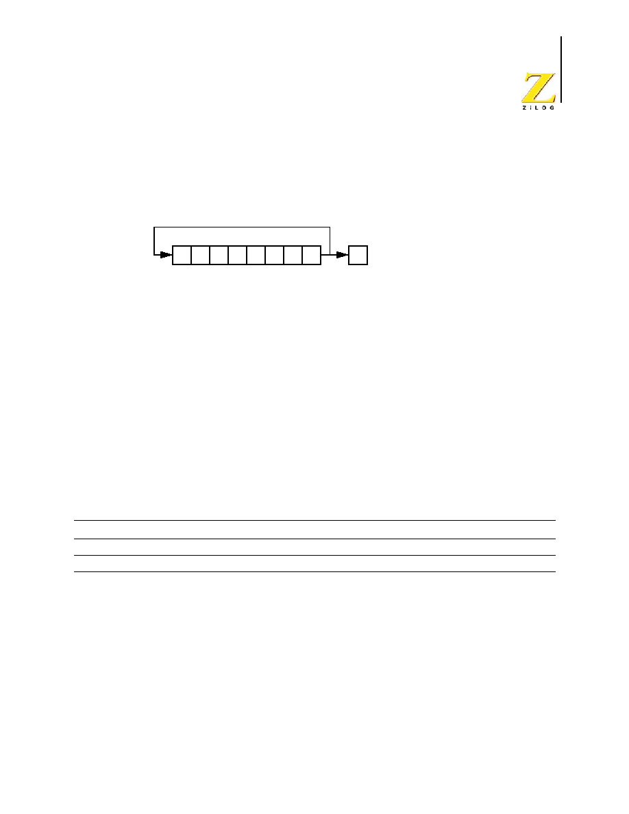
UM012811-0904
eZ8 CPU Instruction Set Description
eZ8 CPU
User Manual
161
RR
Rotate Right
RR dst
Operation
Description
The destination operand contents rotate to the right by one bit position. The initial value of
Bit 0 is moved to Bit 7 and also into the Carry (C) flag.
Flags
Attributes
Escaped Mode Addressing
Using Escaped Mode Addressing, address modes R or IR can specify a Working Register.
If the destination address is prefixed by
EH
(1110B), a Working Register is inferred. For
example, if Working Register R12 (
CH
) is the desired destination operand, use
ECH
as the
destination operand in the opcode. To access Registers with addresses
E0H
to
EFH
, either
set the Working Group Pointer, RP[7:4], to
EH
or use indirect addressing.
C
Set if the bit rotated from the least-significant bit position was 1 (that is., Bit 0 was 1).
Z
Set if the result is zero; reset otherwise.
S
Set if Bit 7 of the result is set; reset otherwise.
V
Set if an arithmetic overflow occurs; reset otherwise.
D
Unaffected.
H
Unaffected.
Mnemonic
Destination
Opcode (Hex)
Operand 1
Operand 2
Operand 3
RR
R1
E0
R1
--
--
RR
@R1
E1
R1
--
--
D7 D6 D5 D4 D3 D2 D1 D0
dst
C

UM012811-0904
eZ8 CPU Instruction Set Description
eZ8 CPU
User Manual
162
Examples
�
If Working Register R6 contains the value
31H
(00110001B), the statement:
RR R6
Object Code: E0 E6
leaves the value
98H
(10011000) in Working Register R6, sets the C, V, and S flags
and clears the Z flag.
�
If Register C6 contains the value
31H
and Register 31H contains the value
7EH
(01111110B), the statement:
RR @C6
Object Code: E1 C6
leaves the value
3FH
(00111111) in Register 31H and clears the C, Z, V, and S flags.

UM012811-0904
eZ8 CPU Instruction Set Description
eZ8 CPU
User Manual
163
RRC
Rotate Right through Carry
RRC dst
Operation
Description
The destination operand contents along with the Carry (C) flag rotate right by one bit posi-
tion. The initial value of Bit 0 replaces the Carry flag and the initial value of the Carry flag
replaces Bit 7.
Flags
Attributes
Escaped Mode Addressing
Using Escaped Mode Addressing, address modes R or IR specify a Working Register. If
the destination address is prefixed by
EH
(1110B), a Working Register is inferred. For
example, if Working Register R12 (
CH
) is the desired destination operand, use
ECH
as the
destination operand in the opcode. To access Registers with addresses
E0H
to
EFH
, either
set the Working Group Pointer, RP[7:4], to
EH
or use indirect addressing.
C
Set if the bit rotated from the least-significant bit position was 1 (that is, Bit 0 was 1).
Z
Set if the result is zero; reset otherwise.
S
Set if Bit 7 of the result is set; reset otherwise.
V
Set if an arithmetic overflow occurs; reset otherwise.
D
Unaffected.
H
Unaffected.
Mnemonic
Destination
Opcode (Hex)
Operand 1
Operand 2
Operand 3
RRC
R1
C0
R1
--
--
RRC
@R1
C1
R1
--
--
D7 D6 D5 D4 D3 D2 D1 D0
dst
C

UM012811-0904
eZ8 CPU Instruction Set Description
eZ8 CPU
User Manual
164
Examples
�
If Register C6H contains the value
DDH
(11011101B) and the Carry flag is reset, the
statement:
RRC C6H
Object Code: C0 C6
leaves the value
6EH
(01101110B) in Register C6H, sets the C and V flags and clears
the Z and S flags.
�
If Register 2C contains the value
EDH
, Register EDH contains the value
00H
(00000000B) and the Carry flag is reset, the statement:
RRC @2CH
Object Code: C1 2C
leaves the value
00H
(00000000B) in Register EDH and resets the C, Z, S, and V
flags.

UM012811-0904
eZ8 CPU Instruction Set Description
eZ8 CPU
User Manual
165
SBC
Subtract with Carry
SBC dst, src
Operation
dst
dst - src - C
Description
This instruction subtracts the source operand and the Carry (C) flag from the destination.
The destination stores the result. The contents of the source operand are unaffected. The
eZ8 CPU performs subtraction by adding the two's-complement of the source operand to
the destination operand. In multiple-precision arithmetic, this instruction permits the carry
(borrow) from the subtraction of low-order operands to be subtracted from the subtraction
of high-order operands.
Flags
Attributes
Escaped Mode Addressing
Using Escaped Mode Addressing, address modes R or IR can specify a Working Register.
If the high nibble of the source or destination address is
EH
(1110B), a Working Register is
inferred. For example, if Working Register R12 (
CH
) is the desired destination operand,
use
ECH
as the destination operand in the opcode. To access Registers with addresses
E0H
to
EFH
, either set the Working Group Pointer, RP[7:4], to
EH
or use indirect addressing.
C
Set if a borrow is required by bit 7; reset otherwise.
Z
Set if the result is zero; reset otherwise.
S
Set if Bit 7 of the result is set; reset otherwise.
V
Set if an arithmetic overflow occurs; reset otherwise.
D
Set to 1.
H
Set if a borrow is required by bit 3; reset otherwise.
Mnemonic
Destination, Source
Opcode (Hex)
Operand 1
Operand 2
Operand 3
SBC
r1, r2
32
{r1, r2}
--
--
SBC
r1, @r2
33
{r1, r2}
--
--
SBC
R1, R2
34
R2
R1
--
SBC
R1, @R2
35
R2
R1
--
SBC
R1, IM
36
R1
IM
--
SBC
@R1, IM
37
R1
IM
--

UM012811-0904
eZ8 CPU Instruction Set Description
eZ8 CPU
User Manual
166
Examples
�
If Working Register R3 contains the value
16H
, the Carry flag is 1, and Working
Register R11 contains the value
20H
, the statement:
SBC R3, R11
Object Code: 32 3B
leaves the value
F5H
in Working Register R3, sets the C, S, and D flags and clears the
Z, V and H flags.
�
If Working Register R15 contains the value
16H
, the Carry flag is not set, Working
Register R10 contains the value
20H
, and Register 20H contains the value
11H
, the
statement:
SBC R15, @R10
Object Code: 33 FA
leaves the value
05H
in Working Register R15, sets the D flag and clears the C, Z, S, V
and H flags.
�
If Register 34H contains the value
2EH
, the Carry flag is set, and Register 12H
contains the value
1BH
, the statement:
SBC 34H, 12H
Object Code: 34 12 34
leaves the value
12H
in Register 34H, sets the D flag and clears the C, Z, S, V and H
flags.
�
If Register 4BH contains the value
82H
, the Carry flag is set, Working Register R3
contains the value
10H
, and Register 10H contains the value
01H
, the statement:
SBC 4BH, @R3
Object Code: 35 E3 4B
leaves the value
80H
in Register 4BH, sets the D and S flags and clears the C, Z, V and
H flags.
�
If Register 6CH contains the value
2AH
, and the Carry flag is not set, the statement:
SBC 6CH, #03H
Object Code: 36 6C 03
leaves the value
27H
in Register 6CH, sets the D flag and clears the C, Z, S, V and H
flags.
�
If Register D4H contains the value
5FH
, Register 5FH contains the value
4CH
, and the
Carry flag is set, the statement:
SBC @D4H, #02H
Object Code: 37 D4 02
leaves the value
49H
in Register 5FH, sets the D flag and clears the C, Z, S, V and H
flags.

UM012811-0904
eZ8 CPU Instruction Set Description
eZ8 CPU
User Manual
167
SBCX
Subtract with Carry using Extended Addressing
SBCX dst, src
Operation
dst
dst - src - C
Description
This instruction subtracts the source operand and the Carry (C) flag from the destination.
The destination stores the result. The contents of the source are unaffected. The eZ8 CPU
performs subtraction by adding the two's-complement of the source operand to the desti-
nation operand. In multiple-precision arithmetic, this instruction permits the carry (bor-
row) from the subtraction of low-order operands to be subtracted from the subtraction of
high-order operands.
Flags
Attributes
Escaped Mode Addressing
Using Escaped Mode Addressing, address mode ER for the source or destination specifies
a Working Register with 4-bit addressing.
If the high byte of the source or destination address is
EEH
(11101110B), a Working Regis-
ter is inferred. For example, the operand
EE3H
selects Working Register R3. The full 12-
bit address is given by {RP[3:0], RP[7:4], 3H}.
To access Registers on Page EH (addresses
E00H
to
EFFH
), set the Page Pointer, RP[3:0],
to
EH
and set the Working Group Pointer, RP[7:4], to the desired Working Group.
C
Set if a borrow is required by bit 7; reset otherwise.
Z
Set if the result is zero; reset otherwise.
S
Set if the result is negative; reset otherwise.
V
Set if an arithmetic overflow occurs; reset otherwise.
D
Set to 1.
H
Set if a borrow is required by bit 3; reset otherwise.
Mnemonic Destination, Source
Opcode (Hex)
Operand 1
Operand 2
Operand 3
SBCX
ER1, ER2
38
ER2[11:4]
{ER2[3:0], ER1[11:8]} ER1[7:0]
SBCX
ER1, IM
39
IM
{0H, ER1[11:8]}
ER1[7:0]

UM012811-0904
eZ8 CPU Instruction Set Description
eZ8 CPU
User Manual
168
Examples
�
If Register 346H contains the value
2EH
, the Carry flag is set, and Register 129H
contains the value
1BH
, the statement:
SBCX 346H, 129H
Object Code: 38 12 93 46
leaves the value
12H
in Register 346H, sets the D flag and clears the C, Z, S, V and H
flags.
�
If Register C6CH contains the value
2AH
and the Carry flag is not set, the statement:
SBCX C6CH, #03H
Object Code: 39 03 0C 6C
leaves the value
27H
in Register C6CH, sets the. D flag and clears the C, Z, S, V and
H.

UM012811-0904
eZ8 CPU Instruction Set Description
eZ8 CPU
User Manual
169
SCF
Set Carry Flag
SCF
Operation
C
1
Description
The Carry (C) flag is 1, regardless of its previous value.
Flags
Attributes
Example
If the Carry flag is currently reset, the statement:
SCF
Object Code: DF
sets the Carry flag to 1.
C
Set to 1.
Z
Unaffected.
S
Unaffected.
V
Unaffected.
D
Unaffected.
H
Unaffected.
Mnemonic
Destination, Source
Opcode (Hex)
Operand 1
Operand 2
Operand 3
SCF
--
DF
--
--
--
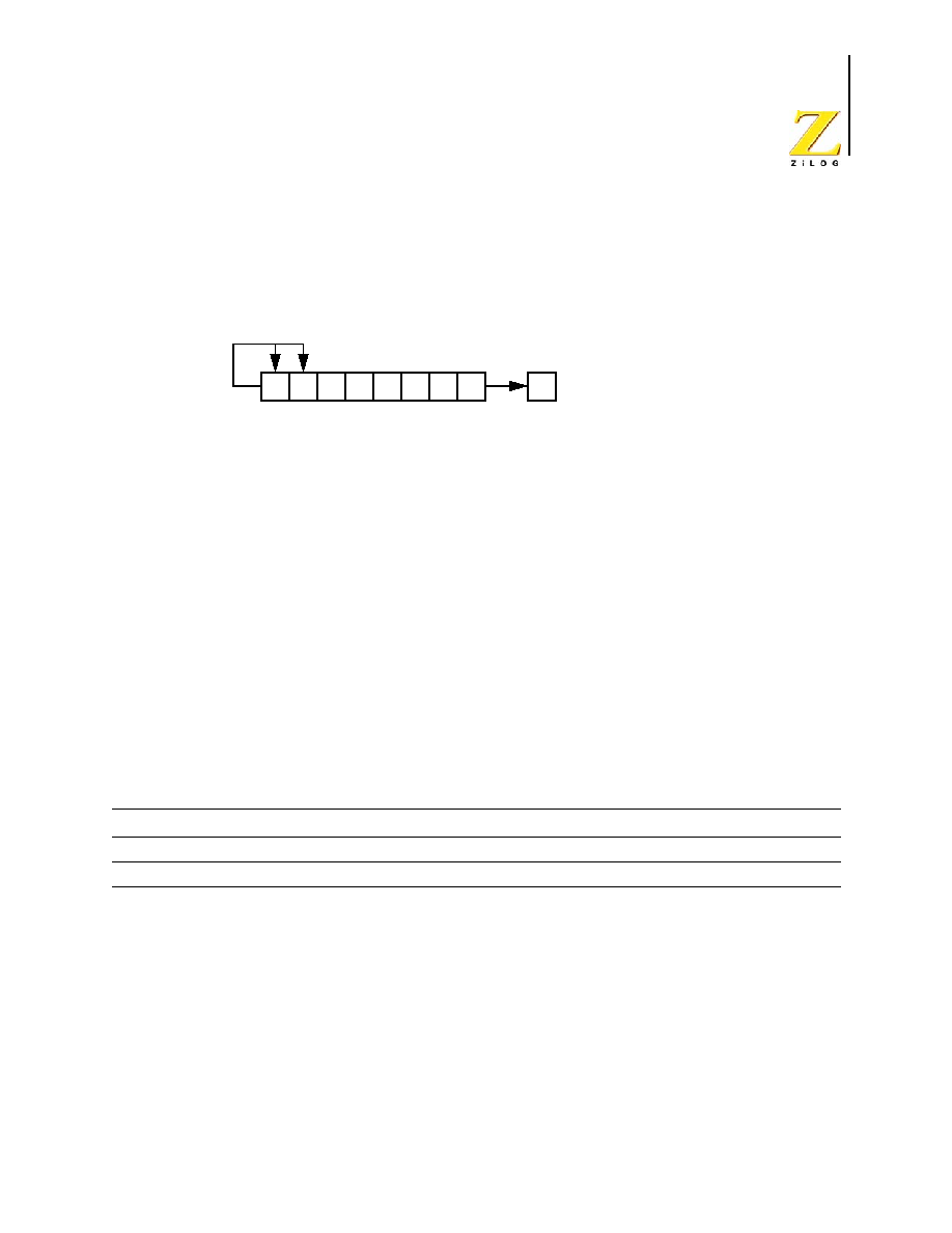
UM012811-0904
eZ8 CPU Instruction Set Description
eZ8 CPU
User Manual
170
SRA
Shift Right Arithmetic
SRA dst
Operation
Description
This instruction performs an arithmetic shift to the right by one bit position on the destina-
tion operand. Bit 0 replaces the Carry (C) flag. The value of Bit 7 (the Sign bit) does not
change, but its value shifts into Bit 6.
Flags
Attributes
Escaped Mode Addressing
Using Escaped Mode Addressing, address modes R or IR can specify a Working Register.
If the destination address is prefixed by
EH
(1110B), a Working Register is inferred. For
example, if Working Register R12 (
CH
) is the desired destination operand, use
ECH
as the
destination operand in the opcode. To access Registers with addresses
E0H
to
EFH
, either
set the Working Group Pointer, RP[7:4], to
EH
or use indirect addressing.
C
Set if the bit rotated from the least-significant bit position was 1 (that is, Bit 0 was 1).
Z
Set if the result is zero; reset otherwise.
S
Set if Bit 7 of the result is set; reset otherwise.
V
Reset to 0.
D
Unaffected.
H
Unaffected.
Mnemonic
Destination
Opcode (Hex)
Operand 1
Operand 2
Operand 3
SRA
R1
D0
R1
--
--
SRA
@R1
D1
R1
--
--
D7 D6 D5 D4 D3 D2 D1 D0
dst
C

UM012811-0904
eZ8 CPU Instruction Set Description
eZ8 CPU
User Manual
171
Examples
�
If Working Register R6 contains the value
31H
(00110001B), the statement:
SRA R6
Object Code: D0 E6
leaves the value
18H
(00011000) in Working Register R6, sets the Carry flag and
clears the Z, V and S flags.
�
If Register C6 contains the value
DFH
, and Register DFH contains the value
B8H
(10111000B), the statement:
SRA @C6
Object Code: D1 C6
leaves the value
DCH
(11011100B) in Register DFH, resets the C, Z and V flags and
sets the S flag.
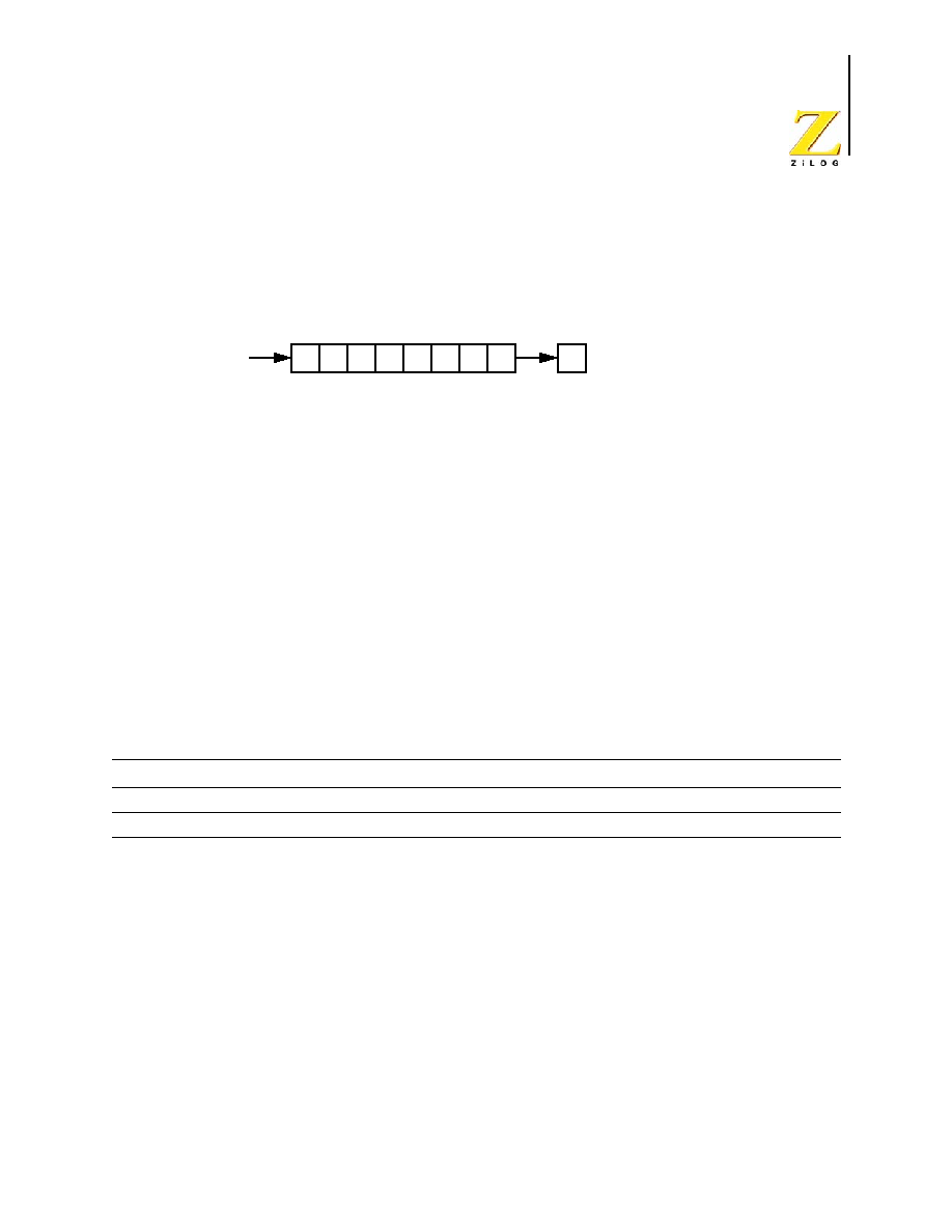
UM012811-0904
eZ8 CPU Instruction Set Description
eZ8 CPU
User Manual
172
SRL
Shift Right Logical
SRL dst
Operation
Description
The destination operand contents shift right logical by one bit position. The initial value of
Bit 0 moves into the Carry (C) flag. Bit 7 resets to 0.
Flags
Attributes
Escaped Mode Addressing
Using Escaped Mode Addressing, address modes R or IR specify a Working Register. If
the destination address is prefixed by
EH
(1110B), a Working Register is inferred. For
example, if Working Register R12 (
CH
) is the desired destination operand, use
ECH
as the
destination operand in the opcode. To access Registers with addresses
E0H
to
EFH
, either
set the Working Group Pointer, RP[7:4], to
EH
or use indirect addressing.
C
Gets value from Bit 0 of the destination.
Z
Set if the result is zero; reset otherwise.
S
Reset to 0.
V
Set if an arithmetic overflow occurs; reset otherwise.
D
Unaffected.
H
Unaffected.
Mnemonic
Destination
Opcode (Hex)
Operand 1
Operand 2
Operand 3
SRL
R1
1F C0
R1
--
--
SRL
@R1
1F C1
R1
--
--
D7 D6 D5 D4 D3 D2 D1 D0
dst
C
0

UM012811-0904
eZ8 CPU Instruction Set Description
eZ8 CPU
User Manual
173
Examples
�
If Working Register R6 contains the value
B1H
(10110001B), the statement:
SRL R6
Object Code: 1F C0 E6
leaves the value
58H
(01011000) in Working Register R6, sets the Carry flag and
clears the Z, V and S flags.
�
If Register C6 contains the value
DFH
, and Register DFH contains the value
F8H
(11111000B), the statement:
SRL @C6
Object Code: 1F C1 C6
leaves the value
7CH
(01111100B) in Register DFH and resets the C, Z, S and V flags.

UM012811-0904
eZ8 CPU Instruction Set Description
eZ8 CPU
User Manual
174
SRP
Set Register Pointer
SRP src
Operation
RP
src
Description
The immediate value loads into the Register Pointer (RP). RP[7:4] sets the current Work-
ing Register Group. RP[3:0] sets the current Register Page.
Flags
Attributes
Example
�
The statement
SRP F0H
Object Code: 01 F0
sets the Register Pointer to access Working Register Group
FH
and Page
0H
in the
Register File. All references to Working Registers now affect this group of 16
registers. Registers
0F0H
to
0FFH
can be accessed as Working Registers R0 to R15.
C
Unaffected.
Z
Unaffected.
S
Unaffected.
V
Unaffected.
D
Unaffected.
H
Unaffected.
Mnemonic
Destination, Source
Opcode (Hex)
Operand 1
Operand 2
Operand 3
SRP
--
01
IM
--
--

UM012811-0904
eZ8 CPU Instruction Set Description
eZ8 CPU
User Manual
175
STOP
STOP Mode
STOP
Operation
Stop Mode.
Description
This instruction places the eZ8 CPU into STOP mode. Refer to the device-specific Product
Specification for details of STOP mode operation.
Flags
Attributes
Example
The statements:
STOP
Object Code: 6F
place the eZ8 CPU into STOP mode.
C
Unaffected.
Z
Unaffected.
S
Unaffected.
V
Unaffected.
D
Unaffected.
H
Unaffected.
Mnemonic
Destination, Source
Opcode (Hex)
Operand 1
Operand 2
Operand 3
STOP
--
6F
--
--
--

UM012811-0904
eZ8 CPU Instruction Set Description
eZ8 CPU
User Manual
176
SUB
Subtract
SUB dst, src
Operation
dst
dst - src
Description
This instruction subtracts the source operand from the destination operand. The destina-
tion operand stores the result. The source operand contents are unaffected. The eZ8 CPU
performs subtraction by adding the two's complement of the source operand to the desti-
nation operand.
Flags
Attributes
Escaped Mode Addressing
Using Escaped Mode Addressing, address modes R or IR specify a Working Register. If
the high nibble of the source or destination address is
EH
(1110B), a Working Register is
inferred. For example, if Working Register R12 (
CH
) is the desired destination operand,
use
ECH
as the destination operand in the opcode. To access Registers with addresses
E0H
to
EFH
, either set the Working Group Pointer, RP[7:4], to
EH
or use indirect addressing.
C
Set if a borrow is required by bit 7; reset otherwise.
Z
Set if the result is zero; reset otherwise.
S
Set if the result is negative; reset otherwise.
V
Set if an arithmetic overflow occurs; reset otherwise.
D
Set to 1.
H
Set if a borrow is required by bit 3; reset otherwise.
Mnemonic
Destination, Source
Opcode (Hex)
Operand 1
Operand 2
Operand 3
SUB
r1, r2
22
{r1, r2}
--
--
SUB
r1, @r2
23
{r1, r2}
--
--
SUB
R1, R2
24
R2
R1
--
SUB
R1, @R2
25
R2
R1
--
SUB
R1, IM
26
R1
IM
--
SUB
@R1, IM
27
R1
IM
--

UM012811-0904
eZ8 CPU Instruction Set Description
eZ8 CPU
User Manual
177
Examples
�
If Working Register R3 contains the value
16H
, and Working Register R11 contains
the value
20H
, the statement:
SUB R3, R11
Object Code: 22 3B
leaves the value
F6H
in Working Register R3, sets the C, S and D flags and clears the
Z, V, and H flags.
�
If Working Register R15 contains the value
16H
, Working Register R10 contains the
value
20H
, and Register 20H contains the value
11H
, the statement:
SUB R15, @R10
Object Code: 23 FA
leaves the value 05H in Working Register R15. The D flag is set, and the C, Z, S, V,
and H flags are cleared.
�
If Register 34H contains the value 2EH, and Register 12H contains the value 1BH, the
statement:
SUB 34H, 12H
Object Code: 24 12 34
leaves the value
13H
in Register 34H, sets the D flag and clears the C, Z, S, V and H
flags are cleared.
�
If Register 4BH contains the value
82H
, Working Register R3 contains the value
10H
,
and Register 10H contains the value
01H
, the statement:
SUB 4BH, @R3
Object Code: 25 E3 4B
leaves the value
81H
in Register 4BH, sets the D and S flags and clears the C, Z, V and
H flags are cleared.
�
If Register 6CH contains the value
2AH
, the statement:
SUB 6CH, #03H
Object Code: 26 6C 03
leaves the value
27H
in Register 6CH, sets the D flag and clears the C, Z, S, V and H
flags are cleared.
�
If Register D4H contains the value
5FH
, Register 5FH contains the value
4CH
, the
statement:
SUB @D4H, #02H
Object Code: 27 D4 02
leaves the value
4AH
in Register 5FH, sets the D flag and clears the C, Z, S, V and H
flags.

UM012811-0904
eZ8 CPU Instruction Set Description
eZ8 CPU
User Manual
178
SUBX
Subtract using Extended Addressing
SUBX dst, src
Operation
dst
dst - src
Description
This instruction subtracts the source operand from the destination operand. The destina-
tion operand stores the result. The source operand contents are unaffected. The eZ8 CPU
performs subtraction by adding the two's complement of the source operand to the desti-
nation operand.
Flags
Attributes
Escaped Mode Addressing
Using Escaped Mode Addressing, address mode ER for the source or destination specifies
a Working Register with 4-bit addressing.
If the high byte of the source or destination address is
EEH
(11101110B), a Working Regis-
ter is inferred. For example, the operand EE3H selects Working Register R3. The full 12-
bit address is given by {RP[3:0], RP[7:4], 3H}.
To access Registers on Page EH (addresses
E00H
to
EFFH
), set the Page Pointer, RP[3:0],
to EH and set the Working Group Pointer, RP[7:4], to the desired Working Group.
C
Set if a borrow is required by bit 7; reset otherwise.
Z
Set if the result is zero; reset otherwise.
S
Set if the result is negative; reset otherwise.
V
Set if an arithmetic overflow occurs; reset otherwise.
D
Set to 1.
H
Set if a borrow is required by bit 3; reset otherwise.
Mnemonic Destination, Source
Opcode (Hex)
Operand 1
Operand 2
Operand 3
SUBX
ER1, ER2
28
ER2[11:4]
{ER2[3:0], ER1[11:8]} ER1[7:0]
SUBX
ER1, IM
29
IM
{0H, ER1[11:8]}
ER1[7:0]

UM012811-0904
eZ8 CPU Instruction Set Description
eZ8 CPU
User Manual
179
Examples
�
If Working Register R3 contains the value
16H
, and Working Register R11 contains
the value
20H
, the statement:
�
If Register 234H contains the value
2EH
, and Register 912H contains the value
1BH
,
the statement:
SUBX 234H, 912H
Object Code: 28 91 22 34
leaves the value
13H
in Register 234H, sets the D flag and clears the C, Z, S, V and H
flags.
�
If Register 56CH contains the value
2AH
, the statement:
SUBX 56CH, #03H
Object Code: 29 03 05 6C
leaves the value
27H
in Register 56CH, sets the D flag and clears the C, Z, S, V and H
flags.

UM012811-0904
eZ8 CPU Instruction Set Description
eZ8 CPU
User Manual
180
SWAP
Swap Nibbles
SWAP dst
Operation
dst[7:4]
dst[3:0]
Description
This instruction swaps the contents of the upper nibble of the destination, dst[7:4], with
the lower nibble of the destination, dst[3:0].
Flags
Attributes
Escaped Mode Addressing
Using Escaped Mode Addressing, address modes R or IR can specify a Working Register.
If the destination address is prefixed by
EH
(1110B), a Working Register is inferred. For
example, if Working Register R12 (
CH
) is the desired destination operand, use
ECH
as the
destination operand in the opcode. To access Registers with addresses
E0H
to
EFH
, either
set the Working Group Pointer, RP[7:4], to
EH
or use indirect addressing.
C
Undefined.
Z
Set if the result is zero; reset otherwise.
S
Set if Bit 7 of the result is set; reset otherwise.
V
Undefined.
D
Unaffected.
H
Unaffected.
Mnemonic
Destination
Opcode (Hex)
Operand 1
Operand 2
Operand 3
SWAP
R1
F0
R1
--
--
SWAP
@R1
F1
R1
--
--

UM012811-0904
eZ8 CPU Instruction Set Description
eZ8 CPU
User Manual
181
Examples
�
If Register BCH contains the value
B3H
(10110011B), the statement:
SWAP BCH
Object Code: F0 BC
leaves the value
3BH
(00111011B) in Register BCH and clears the Z and S flags.
�
If Working Register R5 contains the value
BCH
and Register BCH contains the value
B3H
(10110011B), the statement:
SWAP @R5H
Object Code: F1 E5
leaves the value
3BH
(00111011B) in Register BCH and clears the Z and S flags.

UM012811-0904
eZ8 CPU Instruction Set Description
eZ8 CPU
User Manual
182
TCM
Test Complement Under Mask
TCM dst, src
Operation
(NOT dst) AND src
Description
This instruction tests selected bits in the destination operand for a logical 1 value. Specify
the bits to be tested by setting a 1 bit in the corresponding bit position in the source oper-
and (the mask). The TCM instruction complements the destination operand and AND's it
with the source mask (operand). Check the Zero flag to determine the result. If the Z flag
is set, the tested bits were 1. When a TCM operation is completed, the destination and
source operands retain their original values.
Flags
Attributes
Escaped Mode Addressing
Using Escaped Mode Addressing, address modes R or IR specify a Working Register. If
the high nibble of the source or destination address is
EH
(1110B), a Working Register is
inferred. For example, if Working Register R12 (
CH
) is the desired destination operand,
use ECH as the destination operand in the opcode. To access Registers with addresses
E0H
to
EFH
, either set the Working Group Pointer, RP[7:4], to
EH
or use indirect addressing.
C
Unaffected.
Z
Set if the result is zero; reset otherwise.
S
Set if Bit 7 of the result is set; reset otherwise.
V
Reset to 0.
D
Unaffected.
H
Unaffected.
Mnemonic
Destination, Source
Opcode (Hex)
Operand 1
Operand 2
Operand 3
TCM
r1, r2
62
{r1, r2}
--
--
TCM
r1, @r2
63
{r1, r2}
--
--
TCM
R1, R2
64
R2
R1
--
TCM
R1, @R2
65
R2
R1
--
TCM
R1, IM
66
R1
IM
--
TCM
@R1, IM
67
R1
IM
--

UM012811-0904
eZ8 CPU Instruction Set Description
eZ8 CPU
User Manual
183
Examples
�
If Working Register R3 contains the value
45H
(01000101B) and Working Register
R7 contains the value
01H
(00000001B) (testing bit 0 if it is 1), the statement:
TCM R3, R7
Object Code: 62 37
sets the Z flag indicating bit 0 in the destination operand is 1 and clears the V and S
flags
�
If Working Register R14 contains the value
F3H
(11110011B), Working Register R5
contains the value
CBH
, and Register CBH contains the value
88H
(10001000B)
(testing bits 7 and 3 if they are 1), the statement:
TCM R14, @R5
Object Code: 63 E5
resets the Z flag (because bit 3 in the destination operand is not a 1) and clears the V
and S flags.
�
If Register D4H contains the value
04H
(00000100B), and Working Register R0
contains the value
80H
(10000000B) (testing bit 7 it is 1), the statement:
TCM D4H, R0
Object Code: 64 E0 D4
resets the Z flag (because bit 7 in the destination operand is not a 1), sets the S flag and
clears the V flag.
�
If Register DFH contains the value
FFH
(11111111B), Register 07H contains the value
1FH
, and Register 1FH contains the value
BDH
(10111101B) (testing bits 7, 5, 4, 3, 2,
and bit 0 if they are 1), the statement:
TCM DFH, @07H
Object Code: 65 07 DF
sets the Z flag (indicating the tested bits in the destination operand are 1) and clears
the S and V flags.
�
If Working Register R13 contains the value
F2H
(11110010B), the statement:
TCM R13, #02H
Object Code: 66 ED, 02
tests bit 1 of the destination operand for 1, sets the Z flag (indicating bit 1 in the
destination operand was 1) and clears the S and V flags.
�
If Register 5DH contains the value
A0H
, and Register A0H contains the value
0FH
(00001111B), the statement:
TCM @5D, #10H
Object Code: 67 5D 10

UM012811-0904
eZ8 CPU Instruction Set Description
eZ8 CPU
User Manual
184
tests bit 4 of the Register A0H for 1, resets the Z flag (indicating bit 4 in the
destination operand was not 1) and clears the S and V flags.

UM012811-0904
eZ8 CPU Instruction Set Description
eZ8 CPU
User Manual
185
TCMX
Test Complement Under Mask using Extended Addressing
TCMX dst, src
Operation
(NOT dst) AND src
Description
This instruction tests selected bits in the destination operand for a logical 1 value. Specify
the bits to be tested by setting a 1 bit in the corresponding bit position in the source oper-
and (the mask). The TCMX instruction complements the destination operand and AND's
it with the source mask (operand). Check the Zero flag to determine the result. If the Z flag
is set, then the tested bits are 1. When a TCMX operation is completed, the destination and
source operands still contain their original values.
Flags
Attributes
Escaped Mode Addressing
Using Escaped Mode Addressing, address mode ER for the source or destination specifies
a Working Register with 4-bit addressing.
If the high byte of the source or destination address is
EEH
(11101110B), a Working Regis-
ter is inferred. For example, the operand
EE3H
selects Working Register R3. The full 12-
bit address is given by {RP[3:0], RP[7:4], 3H}.
To access Registers on Page EH (addresses
E00H
to
EFFH
), set the Page Pointer, RP[3:0],
to
EH
and set the Working Group Pointer, RP[7:4], to the desired Working Group.
C
Unaffected.
Z
Set if the result is zero; reset otherwise.
S
Set if the result is negative; reset otherwise.
V
Reset to 0.
D
Unaffected.
H
Unaffected.
Mnemonic Destination, Source
Opcode (Hex)
Operand 1
Operand 2
Operand 3
TCMX
ER1, ER2
68
ER2[11:4]
{ER2[3:0], ER1[11:8]}
ER1[7:0]
TCMX
ER1, IM
69
IM
{0H, ER1[11:8]}
ER1[7:0]

UM012811-0904
eZ8 CPU Instruction Set Description
eZ8 CPU
User Manual
186
Examples
�
If Register DD4H contains the value
04H
(00000100B), and Register 420 contains the
value
80H
(10000000B) (testing bit 7 if it is 1), the statement:
TCMX DD4H, 420H
Object Code: 68 42 0D D4
resets the Z flag (because bit 7 in the destination operand is not a 1), sets the S flag
and clears the V flag.
�
If Register B52H contains the value
F2H
(11110010B), the statement:
TCMX B52H, #02H
Object Code: 66 02 0B 52
tests bit 1 of the destination operand for 1, sets the Z flag (indicating bit 1 in the
destination operand is 1) and clears the S and V flags.

UM012811-0904
eZ8 CPU Instruction Set Description
eZ8 CPU
User Manual
187
TM
Test Under Mask
TM dst, src
Operation
dst AND src
Description
This instruction tests selected bits in the destination operand for a 0 logical value. Specify
the bits to be tested by setting a 1 bit in the corresponding bit position in the source oper-
and (the mask). The TM instruction AND's the destination operand with the source oper-
and (the mask). Check the Zero flag can to determine the result. If the Z flag is set, the
tested bits are 0. When a TM operation is completed, the destination and source operands
retain their original values.
Flags
Attributes
Escaped Mode Addressing
Using Escaped Mode Addressing, address modes R or IR specify a Working Register. If
the high nibble of the source or destination address is
EH
(1110B), a Working Register is
inferred. For example, if Working Register R12 (
CH
) is the desired destination operand,
use
ECH
as the destination operand in the opcode. To access Registers with addresses
E0H
to
EFH
, either set the Working Group Pointer, RP[7:4], to
EH
or use indirect addressing.
C
Unaffected.
Z
Set if the result is zero; reset otherwise.
S
Set if Bit 7 of the result is set; reset otherwise.
V
Reset to 0.
D
Unaffected.
H
Unaffected.
Mnemonic
Destination, Source
Opcode (Hex)
Operand 1
Operand 2
Operand 3
TM
r1, r2
72
{r1, r2}
--
--
TM
r1, @r2
73
{r1, r2}
--
--
TM
R1, R2
74
R2
R1
--
TM
R1, @R2
75
R2
R1
--
TM
R1, IM
76
R1
IM
--
TM
@R1, IM
77
R1
IM
--

UM012811-0904
eZ8 CPU Instruction Set Description
eZ8 CPU
User Manual
188
Examples
�
If Working Register R3 contains the value
45H
(01000101B) and Working Register
R7 contains the value
02H
(00000010B) (testing bit 1 if it is 0), the statement:
TM R3, R7
Object Code: 72 37
sets the Z flag (indicating bit 1 in the destination operand is 0) and clears the V and S
flags.
�
Working Register R14 contains the value
F3H
(11110011B), Working Register R5
contains the value
CBH
, and Register CBH contains the value
88H
(10001000B)
(testing bits 7 and 3 if they are 0), the statement:
TM R14, @R5
Object Code: 73 E5
resets the Z flag (because bit 7 in the destination operand is not a 0), sets the S flag
and clears the V flag.
�
If Register D4H contains the value
08H
(00001000B), and Working Register R0
contains the value
04H
(00000100B) (testing bit 2 if it is 0), the statement:
TM D4H, R0
Object Code: 74 E0 D4
sets the Z flag (because bit 2 in the destination operand is a 0) and clears the S and V
flags.
�
If Register DFH contains the value
00H
(00000000B), Register 07H contains the
value
1FH
, and Register 1FH contains the value
BDH
(10111101B) (testing bits 7, 5, 4,
3, 2, and 0 if they are 0), the statement:
TM DFH, @07H
Object Code: 75 07 DF
sets the Z flag (indicating the tested bits in the destination operand are 0) and clears
the S and V flags.
�
If Working Register R13 contains the value
F1H
(11110001B), the statement:
TM R13, #02H
Object Code: 76 ED, 02
tests bit 1 of the destination operand for 0, sets the Z flag (indicating bit 1 in the
destination operand is 0) and clears the S and V flags.

UM012811-0904
eZ8 CPU Instruction Set Description
eZ8 CPU
User Manual
189
�
If Register 5DH contains the value
A0H
, and Register A0H contains the value
0FH
(00001111B), the statement:
TM @5D, #10H
Object Code: 77 5D 10
tests bit 4 of the Register A0H for 0, sets the Z flag (indicating bit 4 in the destination
operand was 0) and clears the S and V flags.

UM012811-0904
eZ8 CPU Instruction Set Description
eZ8 CPU
User Manual
190
TMX
Test Under Mask using Extended Addressing
TMX dst, src
Operation
dst AND src
Description
This instruction tests selected bits in the destination operand for a logical 0 value. Specify
the bits to be tested by setting a 1 bit in the corresponding bit position in the source oper-
and (the mask). The TMX instruction AND's the destination with the source operand
(mask). Check the Zero flag to determine the result. If the Z flag is set, the tested bits are
0. When a TMX operation is completed, the destination and source operands retain their
original values.
Flags
Attributes
Escaped Mode Addressing
Using Escaped Mode Addressing, address mode ER for the source or destination can spec-
ify a Working Register with 4-bit addressing.
If the high byte of the source or destination address is
EEH
(11101110B), a Working Regis-
ter is inferred. For example, the operand
EE3H
selects Working Register R3. The full 12-
bit address is given by {RP[3:0], RP[7:4], 3H}.
To access Registers on Page EH (addresses E00H to EFFH), set the Page Pointer, RP[3:0],
to
EH
and set the Working Group Pointer, RP[7:4], to the desired Working Group.
C
Unaffected.
Z
Set if the result is zero; reset otherwise.
S
Set if the result is negative; reset otherwise.
V
Reset to 0.
D
Unaffected.
H
Unaffected.
Mnemonic Destination, Source
Opcode (Hex)
Operand 1
Operand 2
Operand 3
TMX
ER1, ER2
78
ER2[11:4]
{ER2[3:0], ER1[11:8]} ER1[7:0]
TMX
ER1, IM
79
IM
{0H, ER1[11:8]}
ER1[7:0]

UM012811-0904
eZ8 CPU Instruction Set Description
eZ8 CPU
User Manual
191
Examples
�
If Register 789H contains the value
45H
(01000101B) and Register 246H contains the
value
02H
(00000010B) (testing bit 1 if it is 0), the statement:
TMX 789H, 246H
Object Code: 78 24 67 89
sets the Z flag (indicating bit 1 in the destination operand is 0) and clears the V and S
flags.
�
If Register 13H contains the value
F1H
(11110001B), the statement:
TMX %013, #02H
Object Code: 79 02 00 13
tests bit 1 of the destination operand for 0 sets the Z flag (indicating bit 1 in the
destination operand is 0) and clears the S and V flags.

UM012811-0904
eZ8 CPU Instruction Set Description
eZ8 CPU
User Manual
192
TRAP
Software Trap
TRAP Vector
Operation
SP
SP - 2
@SP
PC
SP
SP - 1
@SP
Flags
PC
@Vector
Description
This instruction executes a software trap. The Program Counter and Flags are pushed onto
the stack. The eZ8 CPU loads the 16-bit Program Counter with the value stored in the Trap
Vector Pair. Execution begins from the new value in the Program counter. Execute an
IRET instruction to return from a trap.
There are 256 possible Trap Vector Pairs in Program Memory. The Trap Vector Pairs are
numbered from 0 to 255. The base addresses of the Trap Vector Pairs begin at
000H
and
end at
1FEH
(510 decimal). The base address of the Trap Vector Pair is calculated by mul-
tiplying the vector by 2.
Flags
Attributes
Example
�
If Register 68H contains the value
A0H
, and Register 69H contains the value
2FH
, the
statement:
TRAP #%34
Object Code: F2 34
C
Unaffected.
Z
Unaffected.
S
Unaffected.
V
Unaffected.
D
Unaffected.
H
Unaffected.
Mnemonic
Destination
Opcode (Hex)
Operand 1
Operand 2
Operand 3
TRAP
Vector
F2
Vector
--
--

UM012811-0904
eZ8 CPU Instruction Set Description
eZ8 CPU
User Manual
193
pushes the Flags and Program Counter onto the stack. The Program Counter loads the
value
A02FH
. Program execution resumes at address
A02FH
.

UM012811-0904
eZ8 CPU Instruction Set Description
eZ8 CPU
User Manual
194
WDT
Watch-Dog Timer Refresh
WDT
Operation
None.
Description
Enable the Watch-Dog Timer by executing the WDT instruction. Each subsequent execu-
tion of the WDT instruction refreshes the timer and prevents the Watch-Dog Timer from
timing out. For more information on the Watch-Dog Timer, please refer to the relevant
Product Specification for your part.
Flags
Attributes
Examples
�
The first execution of the statement:
WDT
Object Code: 5F
enables the Watch-Dog Timer.
�
If the Watch-Dog Timer is enabled, the statement:
WDT
Object Code: 5F
refreshes the Watch-Dog Timer.
C
Unaffected.
Z
Unaffected.
S
Unaffected.
V
Unaffected.
D
Unaffected.
H
Unaffected.
Mnemonic
Destination, Source
Opcode (Hex)
Operand 1
Operand 2
Operand 3
WDT
--
5F
--
--
--

UM012811-0904
eZ8 CPU Instruction Set Description
eZ8 CPU
User Manual
195
XOR
Logical Exclusive OR
XOR dst, src
Operation
dst
dst XOR src
Description
The source operand is logically EXCLUSIVE OR'ed with the destination operand. An
XOR operation stores a 1 in the destination operand when the corresponding bits in the
two operands are different; otherwise XOR stores a 0. The contents of the source operand
are unaffected.
Flags
Attributes
Escaped Mode Addressing
Using Escaped Mode Addressing, address modes R or IR specify a Working Register. If
the high nibble of the source or destination address is
EH
(1110B), a Working Register is
inferred. For example, if Working Register R12 (
CH
) is the desired destination operand,
use
ECH
as the destination operand in the opcode. To access Registers with addresses
E0H
to
EFH
, either set the Working Group Pointer, RP[7:4], to
EH
or use indirect addressing.
C
Unaffected.
Z
Set if the result is zero; reset otherwise.
S
Set if Bit 7 of the result is set; reset otherwise.
V
Reset to 0.
D
Unaffected.
H
Unaffected.
Mnemonic
Destination, Source
Opcode (Hex)
Operand 1
Operand 2
Operand 3
XOR
r1, r2
B2
{r1, r2}
--
--
XOR
r1, @r2
B3
{r1, r2}
--
--
XOR
R1, R2
B4
R2
R1
--
XOR
R1, @R2
B5
R2
R1
--
XOR
R1, IM
B6
R1
IM
--
XOR
@R1, IM
B7
R1
IM
--

UM012811-0904
eZ8 CPU Instruction Set Description
eZ8 CPU
User Manual
196
Examples
�
If Working Register R1 contains the value
38H
(00111000B) and Working Register
R14 contains the value
8DH
(10001101B), the statement:
XOR R1, R14
Object Code: B2 1E
leaves the value
B5H
(10110101B) in Working Register R1 sets the S flag and clears
the Z and V flags.
�
If Working Register R4 contains the value
F9H
(11111001B), Working Register R13
contains the value
7BH
, and Register 7B contains the value
6AH
(01101010B), the
statement:
XOR R4, @R13
Object Code: B3 4D
leaves the value
93H
(10010011B) in Working Register R4, sets the S flag and clears
the Z and V flags.
�
If Register 3AH contains the value
F5H
(11110101B) and Register 42H contains the
value
0AH
(00001010B), the statement:
XOR 3AH, 42H
Object Code: B4 42 3A
leaves the value
FFH
(11111111B) in Register 3AH, sets the S flag and clears the Z and
V flags.
�
If Working Register R5 contains the value
F0H
(11110000B), Register 45H contains
the value
3AH
, and Register 3AH contains the value
7FH
(01111111B), the statement:
XOR R5, @45H
Object Code: B5 45 E5
leaves the value
8FH
(10001111B) in Working Register R5, sets the S flag and clears
the C and V flags.
�
If Register 7AH contains the value
F7H
(11110111B), the statement:
XOR 7AH, #F0H
Object Code: B6 7A F0
leaves the value
07H
(00000111B) in Register 7AH and clears the Z, V and S.
�
If Working Register R3 contains the value
3EH
and Register 3EH contains the value
6CH
(01101100B), the statement:
XOR @R3, #05H
Object Code: B7 E3 05
leaves the value
69H
(01101001B) in Register 3EH and clears the Z, V, and S flags

UM012811-0904
eZ8 CPU Instruction Set Description
eZ8 CPU
User Manual
197
XORX
Logical Exclusive OR using Extended Addressing
XORX dst, src
Operation
dst
dst XOR src
Description
The source operand is logically EXCLUSIVE OR'ed with the destination operand. An
XORX operation stores a 1 in the destination operand when the corresponding bits in the
two operands are different; otherwise it stores a 0. The contents of the source operand are
unaffected.
Flags
Attributes
Escaped Mode Addressing
Using Escaped Mode Addressing, address mode ER for the source or destination specifies
a Working Register with 4-bit addressing.
If the high byte of the source or destination address is
EEH
(11101110B), a Working Regis-
ter is inferred. For example, the operand
EE3H
selects Working Register R3. The full 12-
bit address is given by {RP[3:0], RP[7:4], 3H}.
To access Registers on Page EH (addresses
E00H
to
EFFH
), set the Page Pointer, RP[3:0],
to
EH
and set the Working Group Pointer, RP[7:4], to the desired Working Group.
C
Unaffected.
Z
Set if the result is zero; reset otherwise.
S
Set if Bit 7 of the result is set; reset otherwise.
V
Reset to 0.
D
Unaffected.
H
Unaffected.
Mnemonic Destination, Source
Opcode (Hex)
Operand 1
Operand 2
Operand 3
XORX
ER1, ER2
B8
ER2[11:4]
{ER2[3:0], ER1[11:8]} ER1[7:0]
XORX
ER1, IM
B9
IM
{0H, ER1[11:8]}
ER1[7:0]

UM012811-0904
eZ8 CPU Instruction Set Description
eZ8 CPU
User Manual
198
Examples
�
If Register 93AH contains the value
F5H
(11110101B) and Register
142H
contains the
value
6AH
(01101010), the statement:
XORX 93AH, 142H
Object Code: B8 14 29 3A
leaves the value
9FH
(10011111B) in Register 93AH, sets the S flag and clears the Z
and V flags.
�
If Register D7AH contains the value
07H
(00000111B), the statement:
XORX D7AH, #01100110B
Object Code: B9 66 0D 7A
leaves the value
61H
(01100001B) in Register 7AH and clears the S, Z and V flags.

eZ8 CPU
User Manual
UM012811-0904
Opcode
Maps
199
Opcode Maps
Figure 23 illustrates opcode map cell description and Table 22 explains the abbreviations
used in Figure 24 and 25.
Figure 23. Opcode Map Cell Description
CP
3.3
R2,R1
A
4
Opcode
Lower Nibble
Second Operand
After Assembly
First Operand
After Assembly
Opcode
Upper Nibble
Instruction Cycles
Fetch Cycles

UM012811-0904
Opcode
Maps
eZ8 CPU
User Manual
200
Table 22. Opcode Map Abbreviations
Abbreviation
Description
Abbreviation
Description
b
Bit position
IRR
Indirect Register Pair
cc
Condition code
p
Polarity (0 or 1)
X
8-bit signed index or displacement r
4-bit Working Register
DA
Destination address
R
8-bit register
ER
Extended Addressing register
r1, R1, Ir1, Irr1, IR1, rr1,
RR1, IRR1, ER1
Destination address
IM
Immediate data value
r2, R2, Ir2, Irr2, IR2, rr2,
RR2, IRR2, ER2
Source address
Ir
Indirect Working Register
RA
Relative
IR
Indirect register
rr
Working Register Pair
Irr
Indirect Working Register Pair
RR
Register Pair
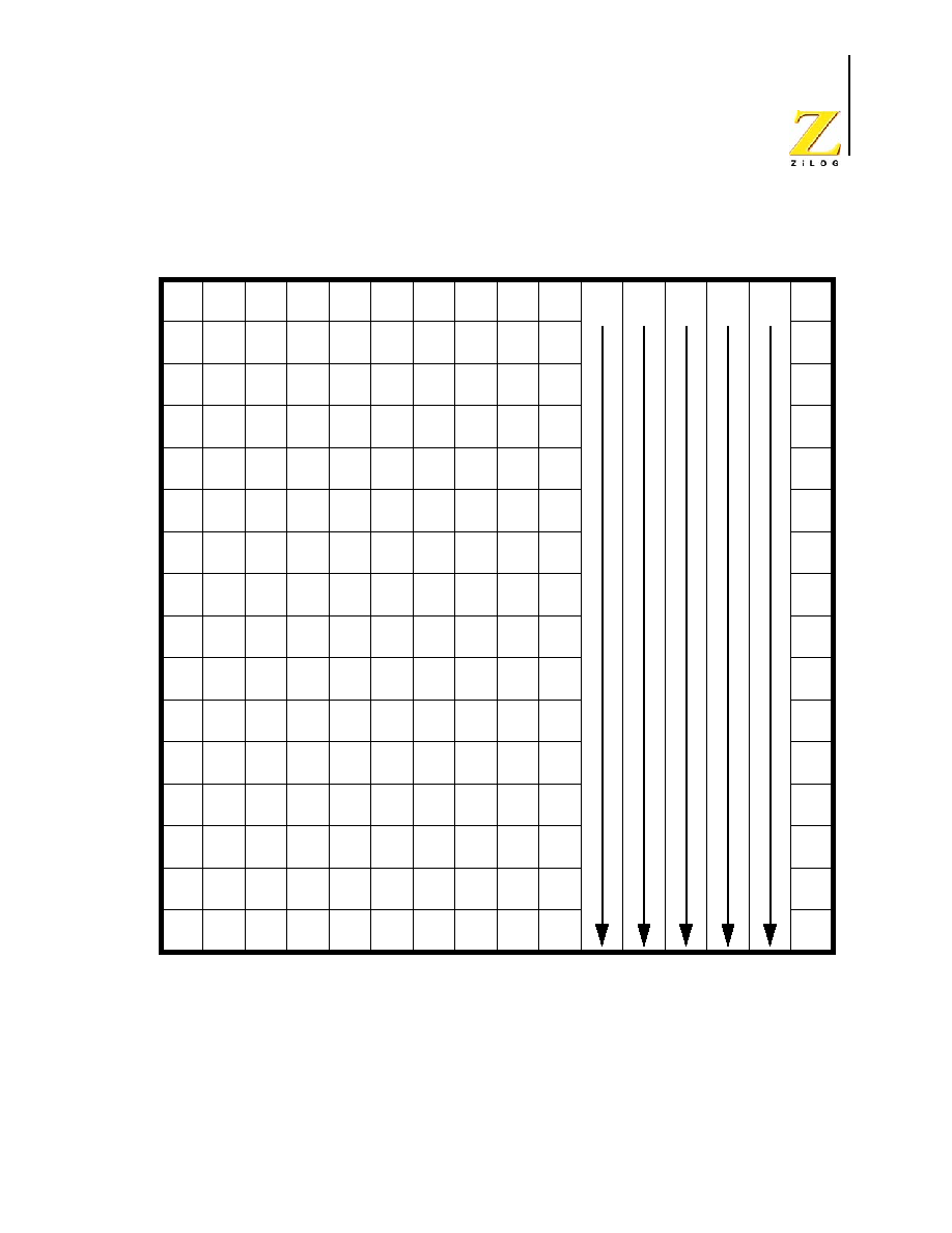
UM012811-0904
Opcode
Maps
eZ8 CPU
User Manual
201
Figure 24. First Opcode Map
CP
3.3
R2,R1
CP
3.4
IR2,R1
CP
2.3
r1,r2
CP
2.4
r1,Ir2
CPX
4.3
ER2,ER1
CPX
4.3
IM,ER1
CP
3.3
R1,IM
CP
3.4
IR1,IM
RRC
2.2
R1
RRC
2.3
IR1
0
1
2
3
4
5
6
7
8
9
A
B
C
D
E
F
0
1
2
3
4
5
6
7
8
9
A
B
C
D
E
F
Lower Nibble (Hex)
Uppe
r Nibb
le
(
H
e
x
)
BRK
1.2
SRP
2.2
IM
ADD
2.3
r1,r2
ADD
2.4
r1,Ir2
ADD
3.3
R2,R1
ADD
3.4
IR2,R1
ADD
3.3
R1,IM
ADD
3.4
IR1,IM
ADDX
4.3
ER2,ER1
ADDX
4.3
IM,ER1
DJNZ
2.3
r1,X
JR
2.2
cc,X
LD
2.2
r1,IM
JP
3.2
cc,DA
INC
1.2
r1
NOP
1.2
RLC
2.2
R1
RLC
2.3
IR1
ADC
2.3
r1,r2
ADC
2.4
r1,Ir2
ADC
3.3
R2,R1
ADC
3.4
IR2,R1
ADC
3.3
R1,IM
ADC
3.4
IR1,IM
ADCX
4.3
ER2,ER1
ADCX
4.3
IM,ER1
INC
2.2
R1
INC
2.3
IR1
SUB
2.3
r1,r2
SUB
2.4
r1,Ir2
SUB
3.3
R2,R1
SUB
3.4
IR2,R1
SUB
3.3
R1,IM
SUB
3.4
IR1,IM
SUBX
4.3
ER2,ER1
SUBX
4.3
IM,ER1
DEC
2.2
R1
DEC
2.3
IR1
SBC
2.3
r1,r2
SBC
2.4
r1,Ir2
SBC
3.3
R2,R1
SBC
3.4
IR2,R1
SBC
3.3
R1,IM
SBC
3.4
IR1,IM
SBCX
4.3
ER2,ER1
SBCX
4.3
IM,ER1
DA
2.2
R1
DA
2.3
IR1
OR
2.3
r1,r2
OR
2.4
r1,Ir2
OR
3.3
R2,R1
OR
3.4
IR2,R1
OR
3.3
R1,IM
OR
3.4
IR1,IM
ORX
4.3
ER2,ER1
ORX
4.3
IM,ER1
POP
2.2
R1
POP
2.3
IR1
AND
2.3
r1,r2
AND
2.4
r1,Ir2
AND
3.3
R2,R1
AND
3.4
IR2,R1
AND
3.3
R1,IM
AND
3.4
IR1,IM
ANDX
4.3
ER2,ER1
ANDX
4.3
IM,ER1
COM
2.2
R1
COM
2.3
IR1
TCM
2.3
r1,r2
TCM
2.4
r1,Ir2
TCM
3.3
R2,R1
TCM
3.4
IR2,R1
TCM
3.3
R1,IM
TCM
3.4
IR1,IM
TCMX
4.3
ER2,ER1
TCMX
4.3
IM,ER1
PUSH
2.2
R2
PUSH
2.3
IR2
TM
2.3
r1,r2
TM
2.4
r1,Ir2
TM
3.3
R2,R1
TM
3.4
IR2,R1
TM
3.3
R1,IM
TM
3.4
IR1,IM
TMX
4.3
ER2,ER1
TMX
4.3
IM,ER1
DECW
2.5
RR1
DECW
2.6
IR1
LDE
2.5
r1,Irr2
LDEI
2.9
Ir1,Irr2
LDX
3.2
r1,ER2
LDX
3.3
Ir1,ER2
LDX
3.4
IRR2,R1
LDX
3.5
IRR2,IR1
LDX
3.4
r1,rr2,X
LDX
3.4
rr1,r2,X
RL
2.2
R1
RL
2.3
IR1
LDE
2.5
r2,Irr1
LDEI
2.9
Ir2,Irr1
LDX
3.2
r2,ER1
LDX
3.3
Ir2,ER1
LDX
3.4
R2,IRR1
LDX
3.5
IR2,IRR1
LEA
3.3
r1,r2,X
LEA
3.5
rr1,rr2,X
INCW
2.5
RR1
INCW
2.6
IR1
CLR
2.2
R1
CLR
2.3
IR1
XOR
2.3
r1,r2
XOR
2.4
r1,Ir2
XOR
3.3
R2,R1
XOR
3.4
IR2,R1
XOR
3.3
R1,IM
XOR
3.4
IR1,IM
XORX
4.3
ER2,ER1
XORX
4.3
IM,ER1
LDC
2.5
r1,Irr2
LDCI
2.9
Ir1,Irr2
LDC
2.5
r2,Irr1
LDCI
2.9
Ir2,Irr1
JP
2.3
IRR1
LDC
2.9
Ir1,Irr2
LD
3.3
r1,r2,X
PUSHX
3.2
ER2
SRA
2.2
R1
SRA
2.3
IR1
POPX
3.2
ER1
LD
3.4
r2,r1,X
CALL
2.6
IRR1
BSWAP
2.2
R1
CALL
3.3
DA
LD
3.2
R2,R1
LD
3.3
IR2,R1
BIT
2.2
p,b,r1
LD
2.3
r1,Ir2
LDX
4.2
ER2,ER1
LDX
4.2
IM,ER1
LD
3.2
R1,IM
LD
3.3
IR1,IM
RR
2.2
R1
RR
2.3
IR1
MULT
2.8
RR1
LD
3.3
R2,IR1
TRAP
2.6
Vector
LD
2.3
Ir1,r2
BTJ
3.3
p,b,r1,X
BTJ
3.4
p,b,Ir1,X
SWAP
2.2
R1
SWAP
2.3
IR1
RCF
1.2
WDT
1.2
STOP
1.2
HALT
1.2
DI
1.2
EI
1.2
RET
1.4
IRET
1.5
SCF
1.2
CCF
1.2
Opcode
See 2nd
Map
1,2
ATM
UM012811-0904
Opcode
Maps
eZ8 CPU
User Manual
202
Figure 25. Second Opcode Map after 1FH
CPC
4.3
R2,R1
CPC
4.4
IR2,R1
CPC
3.3
r1,r2
CPC
3.4
r1,Ir2
CPCX
5.3
ER2,ER1
CPCX
5.3
IM,ER1
CPC
4.3
R1,IM
CPC
4.4
IR1,IM
SRL
3.2
R1
SRL
3.3
IR1
0
1
2
3
4
5
6
7
8
9
A
B
C
D
E
F
0
1
2
3
4
5
6
7
8
9
A
B
C
D
E
F
Lower Nibble (Hex)
Uppe
r Nibb
le
(
H
e
x
)
3,2
PUSH
IM
5,4
LDWX
ER1,ER2

eZ8 CPU
User Manual
UM012811-0904
Opcodes Listed Numerically
203
Opcodes Listed Numerically
Table 23 lists the eZ8 CPU instructions, sorted numerically by the opcode. The table iden-
tifies the addressing modes employed by the instruction, the effect upon the Flags register,
the number of CPU clock cycles required for the instruction fetch, and the number of CPU
clock cycles required for the instruction execution.
.
Table 23. eZ8 CPU Instructions Sorted by Opcode
Opcode(s)
(Hex)
Assembly Mnemonic
Address Mode
Flags
Fetch
Cycles
Instr.
Cycles
dst
src
C
Z
S
V
D
H
00
BRK
-
-
-
-
-
-
1
2
01
SRP src
IM
-
-
-
-
-
-
2
2
02
ADD dst, src
r
r
*
*
*
*
0
*
2
3
03
ADD dst, src
r
Ir
*
*
*
*
0
*
2
4
04
ADD dst, src
R
R
*
*
*
*
0
*
3
3
05
ADD dst, src
R
IR
*
*
*
*
0
*
3
4
06
ADD dst, src
R
IM
*
*
*
*
0
*
3
3
07
ADD dst, src
IR
IM
*
*
*
*
0
*
3
4
08
ADDX dst, src
ER
ER
*
*
*
*
0
*
4
3
09
ADDX dst, src
ER
IM
*
*
*
*
0
*
4
3
0A
DJNZ dst, RA
r
-
-
-
-
-
-
2
3
0B
JR F, dst
DA
-
-
-
-
-
-
2
2
0C
LD dst, src
r
IM
-
-
-
-
-
-
2
2
0D
JP F, dst
DA
-
-
-
-
-
-
3
2
0E
INC dst
r
-
*
*
*
-
-
1
2
0F
NOP
-
-
-
-
-
-
1
2
10
RLC dst
R
*
*
*
*
-
-
2
2
Flags Notation: * = Value is a function of the result of the operation.
- = Unaffected
X = Undefined
0 = Reset to 0
1 = Set to 1

UM012811-0904
Opcodes Listed Numerically
eZ8 CPU
User Manual
204
11
RLC dst
IR
*
*
*
*
-
-
2
3
12
ADC dst, src
r
r
*
*
*
*
0
*
2
3
13
ADC dst, src
r
Ir
*
*
*
*
0
*
2
4
14
ADC dst, src
R
R
*
*
*
*
0
*
3
3
15
ADC dst, src
R
IR
*
*
*
*
0
*
3
4
16
ADC dst, src
R
IM
*
*
*
*
0
*
3
3
17
ADC dst, src
IR
IM
*
*
*
*
0
*
3
4
18
ADCX dst, src
ER
ER
*
*
*
*
0
*
4
3
19
ADCX dst, src
ER
IM
*
*
*
*
0
*
4
3
1A
DJNZ dst, RA
r
-
-
-
-
-
-
2
3
1B
JR LT, dst
DA
-
-
-
-
-
-
2
2
1C
LD dst, src
r
IM
-
-
-
-
-
-
2
2
1D
JP LT, dst
DA
-
-
-
-
-
-
3
2
1E
INC dst
r
-
*
*
*
-
-
1
2
1F70
PUSH src
IM
-
-
-
-
-
-
3
2
1F A2
CPC dst, src
r
r
*
*
*
*
-
-
3
3
1F A3
CPC dst, src
r
Ir
*
*
*
*
-
-
3
4
1F A4
CPC dst, src
R
R
*
*
*
*
-
-
4
3
1F A5
CPC dst, src
R
IR
*
*
*
*
-
-
4
4
1F A6
CPC dst, src
R
IM
*
*
*
*
-
-
4
3
1F A7
CPC dst, src
IR
IM
*
*
*
*
-
-
4
4
1F A8
CPCX dst, src
ER
ER
*
*
*
*
-
-
5
3
1F A9
CPCX dst, src
ER
IM
*
*
*
*
-
-
5
3
1F C0
SRL dst
R
*
*
0
*
-
-
3
2
1F C1
SRL dst
IR
*
*
0
*
-
-
3
3
1FE8
LDWX dst, src
ER
ER
-
-
-
-
-
-
5
4
Table 23. eZ8 CPU Instructions Sorted by Opcode
Opcode(s)
(Hex)
Assembly Mnemonic
Address Mode
Flags
Fetch
Cycles
Instr.
Cycles
dst
src
C
Z
S
V
D
H
Flags Notation: * = Value is a function of the result of the operation.
- = Unaffected
X = Undefined
0 = Reset to 0
1 = Set to 1

UM012811-0904
Opcodes Listed Numerically
eZ8 CPU
User Manual
205
20
INC dst
R
-
*
*
*
-
-
2
2
21
INC dst
IR
-
*
*
*
-
-
2
3
22
SUB dst, src
r
r
*
*
*
*
1
*
2
3
23
SUB dst, src
r
Ir
*
*
*
*
1
*
2
4
24
SUB dst, src
R
R
*
*
*
*
1
*
3
3
25
SUB dst, src
R
IR
*
*
*
*
1
*
3
4
26
SUB dst, src
R
IM
*
*
*
*
1
*
3
3
27
SUB dst, src
IR
IM
*
*
*
*
1
*
3
4
28
SUBX dst, src
ER
ER
*
*
*
*
1
*
4
3
29
SUBX dst, src
ER
IM
*
*
*
*
1
*
4
3
2A
DJNZ dst, RA
r
-
-
-
-
-
-
2
3
2B
JR LE, dst
DA
-
-
-
-
-
-
2
2
2C
LD dst, src
r
IM
-
-
-
-
-
-
2
2
2D
JP LE, dst
DA
-
-
-
-
-
-
3
2
2E
INC dst
r
-
*
*
*
-
-
1
2
2F
ATM
-
-
-
-
-
-
1
2
30
DEC dst
R
-
*
*
*
-
-
2
2
31
DEC dst
IR
-
*
*
*
-
-
2
3
32
SBC dst, src
r
r
*
*
*
*
1
*
2
3
33
SBC dst, src
r
Ir
*
*
*
*
1
*
2
4
34
SBC dst, src
R
R
*
*
*
*
1
*
3
3
35
SBC dst, src
R
IR
*
*
*
*
1
*
3
4
36
SBC dst, src
R
IM
*
*
*
*
1
*
3
3
37
SBC dst, src
IR
IM
*
*
*
*
1
*
3
4
38
SBCX dst, src
ER
ER
*
*
*
*
1
*
4
3
39
SBCX dst, src
ER
IM
*
*
*
*
1
*
4
3
Table 23. eZ8 CPU Instructions Sorted by Opcode
Opcode(s)
(Hex)
Assembly Mnemonic
Address Mode
Flags
Fetch
Cycles
Instr.
Cycles
dst
src
C
Z
S
V
D
H
Flags Notation: * = Value is a function of the result of the operation.
- = Unaffected
X = Undefined
0 = Reset to 0
1 = Set to 1

UM012811-0904
Opcodes Listed Numerically
eZ8 CPU
User Manual
206
3A
DJNZ dst, RA
r
-
-
-
-
-
-
2
3
3B
JR ULE, dst
DA
-
-
-
-
-
-
2
2
3C
LD dst, src
r
IM
-
-
-
-
-
-
2
2
3D
JP ULE, dst
DA
-
-
-
-
-
-
3
2
3E
INC dst
r
-
*
*
*
-
-
1
2
40
DA dst
R
*
*
*
X
-
-
2
2
41
DA dst
IR
*
*
*
X
-
-
2
3
42
OR dst, src
r
r
-
*
*
0
-
-
2
3
43
OR dst, src
r
Ir
-
*
*
0
-
-
2
4
44
OR dst, src
R
R
-
*
*
0
-
-
3
3
45
OR dst, src
R
IR
-
*
*
0
-
-
3
4
46
OR dst, src
R
IM
-
*
*
0
-
-
3
3
47
OR dst, src
IR
IM
-
*
*
0
-
-
3
4
48
ORX dst, src
ER
ER
-
*
*
0
-
-
4
3
49
ORX dst, src
ER
IM
-
*
*
0
-
-
4
3
4A
DJNZ dst, RA
r
-
-
-
-
-
-
2
3
4B
JR OV, dst
DA
-
-
-
-
-
-
2
2
4C
LD dst, src
r
IM
-
-
-
-
-
-
2
2
4D
JP OV, dst
DA
-
-
-
-
-
-
3
2
4E
INC dst
r
-
*
*
*
-
-
1
2
50
POP dst
R
-
-
-
-
-
-
2
2
51
POP dst
IR
-
-
-
-
-
-
2
3
52
AND dst, src
r
r
-
*
*
0
-
-
2
3
53
AND dst, src
r
Ir
-
*
*
0
-
-
2
4
54
AND dst, src
R
R
-
*
*
0
-
-
3
3
55
AND dst, src
R
IR
-
*
*
0
-
-
3
4
Table 23. eZ8 CPU Instructions Sorted by Opcode
Opcode(s)
(Hex)
Assembly Mnemonic
Address Mode
Flags
Fetch
Cycles
Instr.
Cycles
dst
src
C
Z
S
V
D
H
Flags Notation: * = Value is a function of the result of the operation.
- = Unaffected
X = Undefined
0 = Reset to 0
1 = Set to 1

UM012811-0904
Opcodes Listed Numerically
eZ8 CPU
User Manual
207
56
AND dst, src
R
IM
-
*
*
0
-
-
3
3
57
AND dst, src
IR
IM
-
*
*
0
-
-
3
4
58
ANDX dst, src
ER
ER
-
*
*
0
-
-
4
3
59
ANDX dst, src
ER
IM
-
*
*
0
-
-
4
3
5A
DJNZ dst, RA
r
-
-
-
-
-
-
2
3
5B
JR MI, dst
DA
-
-
-
-
-
-
2
2
5C
LD dst, src
r
IM
-
-
-
-
-
-
2
2
5D
JP MI, dst
DA
-
-
-
-
-
-
3
2
5E
INC dst
r
-
*
*
*
-
-
1
2
5F
WDT
-
-
-
-
-
-
1
2
60
COM dst
R
-
*
*
0
-
-
2
2
61
COM dst
IR
-
*
*
0
-
-
2
3
62
TCM dst, src
r
r
-
*
*
0
-
-
2
3
63
TCM dst, src
r
Ir
-
*
*
0
-
-
2
4
64
TCM dst, src
R
R
-
*
*
0
-
-
3
3
65
TCM dst, src
R
IR
-
*
*
0
-
-
3
4
66
TCM dst, src
R
IM
-
*
*
0
-
-
3
3
67
TCM dst, src
IR
IM
-
*
*
0
-
-
3
4
68
TCMX dst, src
ER
ER
-
*
*
0
-
-
4
3
69
TCMX dst, src
ER
IM
-
*
*
0
-
-
4
3
6A
DJNZ dst, RA
r
-
-
-
-
-
-
2
3
6B
JR Z, dst
DA
-
-
-
-
-
-
2
2
6C
LD dst, src
r
IM
-
-
-
-
-
-
2
2
6D
JP Z, dst
DA
-
-
-
-
-
-
3
2
6E
INC dst
r
-
*
*
*
-
-
1
2
6F
STOP
-
-
-
-
-
-
1
2
Table 23. eZ8 CPU Instructions Sorted by Opcode
Opcode(s)
(Hex)
Assembly Mnemonic
Address Mode
Flags
Fetch
Cycles
Instr.
Cycles
dst
src
C
Z
S
V
D
H
Flags Notation: * = Value is a function of the result of the operation.
- = Unaffected
X = Undefined
0 = Reset to 0
1 = Set to 1

UM012811-0904
Opcodes Listed Numerically
eZ8 CPU
User Manual
208
70
PUSH src
R
-
-
-
-
-
-
2
2
71
PUSH src
IR
-
-
-
-
-
-
2
3
72
TM dst, src
r
r
-
*
*
0
-
-
2
3
73
TM dst, src
r
Ir
-
*
*
0
-
-
2
4
74
TM dst, src
R
R
-
*
*
0
-
-
3
3
75
TM dst, src
R
IR
-
*
*
0
-
-
3
4
76
TM dst, src
R
IM
-
*
*
0
-
-
3
3
77
TM dst, src
IR
IM
-
*
*
0
-
-
3
4
78
TMX dst, src
ER
ER
-
*
*
0
-
-
4
3
79
TMX dst, src
ER
IM
-
*
*
0
-
-
4
3
7A
DJNZ dst, RA
r
-
-
-
-
-
-
2
3
7B
JR C, dst
DA
-
-
-
-
-
-
2
2
7C
LD dst, src
r
IM
-
-
-
-
-
-
2
2
7D
JP C, dst
DA
-
-
-
-
-
-
3
2
7E
INC dst
r
-
*
*
*
-
-
1
2
7F
HALT
-
-
-
-
-
-
1
2
80
DECW dst
RR
-
*
*
*
-
-
2
5
81
DECW dst
IRR
-
*
*
*
-
-
2
6
82
LDE dst, src
r
Irr
-
-
-
-
-
-
2
5
83
LDEI dst, src
Ir
Irr
-
-
-
-
-
-
2
9
84
LDX dst, src
r
ER
-
-
-
-
-
-
3
2
85
LDX dst, src
Ir
ER
-
-
-
-
-
-
3
3
86
LDX dst, src
R
IRR
-
-
-
-
-
-
3
4
87
LDX dst, src
IR
IRR
-
-
-
-
-
-
3
5
88
LDX dst, src
r
X(rr)
-
-
-
-
-
-
3
4
89
LDX dst, src
X(rr)
r
-
-
-
-
-
-
3
4
Table 23. eZ8 CPU Instructions Sorted by Opcode
Opcode(s)
(Hex)
Assembly Mnemonic
Address Mode
Flags
Fetch
Cycles
Instr.
Cycles
dst
src
C
Z
S
V
D
H
Flags Notation: * = Value is a function of the result of the operation.
- = Unaffected
X = Undefined
0 = Reset to 0
1 = Set to 1

UM012811-0904
Opcodes Listed Numerically
eZ8 CPU
User Manual
209
8A
DJNZ dst, RA
r
-
-
-
-
-
-
2
3
8B
JR dst
DA
-
-
-
-
-
-
2
2
8C
LD dst, src
r
IM
-
-
-
-
-
-
2
2
8D
JP dst
DA
-
-
-
-
-
-
3
2
8E
INC dst
r
-
*
*
*
-
-
1
2
8F
DI
-
-
-
-
-
-
1
2
90
RL dst
R
*
*
*
*
-
-
2
2
91
RL dst
IR
*
*
*
*
-
-
2
3
92
LDE dst, src
Irr
r
-
-
-
-
-
-
2
5
93
LDEI dst, src
Irr
Ir
-
-
-
-
-
-
2
9
94
LDX dst, src
ER
r
-
-
-
-
-
-
3
2
95
LDX dst, src
ER
Ir
-
-
-
-
-
-
3
3
96
LDX dst, src
IRR
R
-
-
-
-
-
-
3
4
97
LDX dst, src
IRR
IR
-
-
-
-
-
-
3
5
98
LEA dst, X(src)
r
X(r)
-
-
-
-
-
-
3
3
99
LEA dst, X(src)
rr
X(rr)
-
-
-
-
-
-
3
5
9A
DJNZ dst, RA
r
-
-
-
-
-
-
2
3
9B
JR GE, dst
DA
-
-
-
-
-
-
2
2
9C
LD dst, src
r
IM
-
-
-
-
-
-
2
2
9D
JP GE, dst
DA
-
-
-
-
-
-
3
2
9E
INC dst
r
-
*
*
*
-
-
1
2
9F
EI
-
-
-
-
-
-
1
2
A0
INCW dst
RR
-
*
*
*
-
-
2
5
A1
INCW dst
IRR
-
*
*
*
-
-
2
6
A2
CP dst, src
r
r
*
*
*
*
-
-
2
3
A3
CP dst, src
r
Ir
*
*
*
*
-
-
2
4
Table 23. eZ8 CPU Instructions Sorted by Opcode
Opcode(s)
(Hex)
Assembly Mnemonic
Address Mode
Flags
Fetch
Cycles
Instr.
Cycles
dst
src
C
Z
S
V
D
H
Flags Notation: * = Value is a function of the result of the operation.
- = Unaffected
X = Undefined
0 = Reset to 0
1 = Set to 1

UM012811-0904
Opcodes Listed Numerically
eZ8 CPU
User Manual
210
A4
CP dst, src
R
R
*
*
*
*
-
-
3
3
A5
CP dst, src
R
IR
*
*
*
*
-
-
3
4
A6
CP dst, src
R
IM
*
*
*
*
-
-
3
3
A7
CP dst, src
IR
IM
*
*
*
*
-
-
3
4
A8
CPX dst, src
ER
ER
*
*
*
*
-
-
4
3
A9
CPX dst, src
ER
IM
*
*
*
*
-
-
4
3
AA
DJNZ dst, RA
r
-
-
-
-
-
-
2
3
AB
JR GT, dst
DA
-
-
-
-
-
-
2
2
AC
LD dst, src
r
IM
-
-
-
-
-
-
2
2
AD
JP GT, dst
DA
-
-
-
-
-
-
3
2
AE
INC dst
r
-
*
*
*
-
-
1
2
AF
RET
-
-
-
-
-
-
1
4
B0
CLR dst
R
-
-
-
-
-
-
2
2
B1
CLR dst
IR
-
-
-
-
-
-
2
3
B2
XOR dst, src
r
r
-
*
*
0
-
-
2
3
B3
XOR dst, src
r
Ir
-
*
*
0
-
-
2
4
B4
XOR dst, src
R
R
-
*
*
0
-
-
3
3
B5
XOR dst, src
R
IR
-
*
*
0
-
-
3
4
B6
XOR dst, src
R
IM
-
*
*
0
-
-
3
3
B7
XOR dst, src
IR
IM
-
*
*
0
-
-
3
4
B8
XORX dst, src
ER
ER
-
*
*
0
-
-
4
3
B9
XORX dst, src
ER
IM
-
*
*
0
-
-
4
3
BA
DJNZ dst, R
r
-
-
-
-
-
-
2
3
BB
JR UGT, dst
DA
-
-
-
-
-
-
2
2
BC
LD dst, src
r
IM
-
-
-
-
-
-
2
2
BD
JP UGT, dst
DA
-
-
-
-
-
-
3
2
Table 23. eZ8 CPU Instructions Sorted by Opcode
Opcode(s)
(Hex)
Assembly Mnemonic
Address Mode
Flags
Fetch
Cycles
Instr.
Cycles
dst
src
C
Z
S
V
D
H
Flags Notation: * = Value is a function of the result of the operation.
- = Unaffected
X = Undefined
0 = Reset to 0
1 = Set to 1

UM012811-0904
Opcodes Listed Numerically
eZ8 CPU
User Manual
211
BE
INC dst
r
-
*
*
*
-
-
1
2
BF
IRET
*
*
*
*
*
*
1
5
C0
RRC dst
R
*
*
*
*
-
-
2
2
C1
RRC dst
IR
*
*
*
*
-
-
2
3
C2
LDC dst, src
r
Irr
-
-
-
-
-
-
2
5
C3
LDCI dst, src
Ir
Irr
-
-
-
-
-
-
2
9
C4
JP dst
IRR
-
-
-
-
-
-
2
3
C5
LDC dst, src
Ir
Irr
-
-
-
-
-
-
2
9
C7
LD dst, src
r
X(r)
-
-
-
-
-
-
3
3
C8
PUSHX src
ER
-
-
-
-
-
-
3
2
CA
DJNZ dst, RA
r
-
-
-
-
-
-
2
3
CB
JR NOV, dst
DA
-
-
-
-
-
-
2
2
CC
LD dst, src
r
IM
-
-
-
-
-
-
2
2
CD
JP NOV, dst
DA
-
-
-
-
-
-
3
2
CE
INC dst
r
-
*
*
*
-
-
1
2
CF
RCF
0
-
-
-
-
-
1
2
D0
SRA dst
R
*
*
*
0
-
-
2
2
D1
SRA dst
IR
*
*
*
0
-
-
2
3
D2
LDC dst, src
Irr
r
-
-
-
-
-
-
2
5
D3
LDCI dst, src
Irr
Ir
-
-
-
-
-
-
2
9
D4
CALL dst
IRR
-
-
-
-
-
-
2
6
D5
BSWAP dst
R
X
*
*
0
-
-
2
2
D6
CALL dst
DA
-
-
-
-
-
-
3
3
D7
LD dst, src
X(r)
r
-
-
-
-
-
-
3
4
D8
POPX dst
ER
-
-
-
-
-
-
3
2
DA
DJNZ dst, RA
r
-
-
-
-
-
-
2
3
Table 23. eZ8 CPU Instructions Sorted by Opcode
Opcode(s)
(Hex)
Assembly Mnemonic
Address Mode
Flags
Fetch
Cycles
Instr.
Cycles
dst
src
C
Z
S
V
D
H
Flags Notation: * = Value is a function of the result of the operation.
- = Unaffected
X = Undefined
0 = Reset to 0
1 = Set to 1

UM012811-0904
Opcodes Listed Numerically
eZ8 CPU
User Manual
212
DB
JR PL, dst
DA
-
-
-
-
-
-
2
2
DC
LD dst, src
r
IM
-
-
-
-
-
-
2
2
DD
JP PL, dst
DA
-
-
-
-
-
-
3
2
DE
INC dst
r
-
*
*
*
-
-
1
2
DF
SCF
1
-
-
-
-
-
1
2
E0
RR dst
R
*
*
*
*
-
-
2
2
E1
RR dst
IR
*
*
*
*
-
-
2
3
E2
BIT p, bit, dst
r
-
*
*
0
-
-
2
2
E3
LD dst, src
r
Ir
-
-
-
-
-
-
2
3
E4
LD dst, src
R
R
-
-
-
-
-
-
3
2
E5
LD dst, src
R
IR
-
-
-
-
-
-
3
4
E6
LD dst, src
R
IM
-
-
-
-
-
-
3
2
E7
LD dst, src
IR
IM
-
-
-
-
-
-
3
3
E8
LDX dst, src
ER
ER
-
-
-
-
-
-
4
2
E9
LDX dst, src
ER
IM
-
-
-
-
-
-
4
2
EA
DJNZ dst, RA
r
-
-
-
-
-
-
2
3
EB
JR NZ, dst
DA
-
-
-
-
-
-
2
2
EC
LD dst, src
r
IM
-
-
-
-
-
-
2
2
ED
JP NZ, dst
DA
-
-
-
-
-
-
3
2
EE
INC dst
r
-
*
*
*
-
-
1
2
EF
CCF
*
-
-
-
-
-
1
2
F0
SWAP dst
R
X
*
*
X
-
-
2
2
F1
SWAP dst
IR
X
*
*
X
-
-
2
3
F2
TRAP Vector
Vector
-
-
-
-
-
-
2
6
F3
LD dst, src
Ir
r
-
-
-
-
-
-
2
3
F4
MULT dst
RR
-
-
-
-
-
-
2
8
Table 23. eZ8 CPU Instructions Sorted by Opcode
Opcode(s)
(Hex)
Assembly Mnemonic
Address Mode
Flags
Fetch
Cycles
Instr.
Cycles
dst
src
C
Z
S
V
D
H
Flags Notation: * = Value is a function of the result of the operation.
- = Unaffected
X = Undefined
0 = Reset to 0
1 = Set to 1

UM012811-0904
Opcodes Listed Numerically
eZ8 CPU
User Manual
213
F5
LD dst, src
IR
R
-
-
-
-
-
-
3
3
F6
BTJ p, bit, src, dst
r
-
-
-
-
-
-
3
3
F7
BTJ p, bit, src, dst
Ir
-
-
-
-
-
-
3
4
FA
DJNZ dst, RA
r
-
-
-
-
-
-
2
3
FB
JR NC, dst
DA
-
-
-
-
-
-
2
2
FC
LD dst, src
r
IM
-
-
-
-
-
-
2
2
FD
JP NC, dst
DA
-
-
-
-
-
-
3
2
FE
INC dst
r
-
*
*
*
-
-
1
2
Table 23. eZ8 CPU Instructions Sorted by Opcode
Opcode(s)
(Hex)
Assembly Mnemonic
Address Mode
Flags
Fetch
Cycles
Instr.
Cycles
dst
src
C
Z
S
V
D
H
Flags Notation: * = Value is a function of the result of the operation.
- = Unaffected
X = Undefined
0 = Reset to 0
1 = Set to 1

eZ8 CPU
User Manual
UM012811-0904
Assembly and Object Code Example
214
Assembly and Object Code Example
Table 24 provides an example listing file output for an assembled eZ8 CPU program. Most
of the opcodes appear in this list. The table is sorted alphabetically by the instruction mne-
monics. Each instruction line consists of the Program Counter address for the instruction,
the object code, and the assembly code (instruction and operands). The "ORG %1000"
assembly code is an assembler directive which sets the base Program Counter value. The
labels (LABEL1:, LABEL2:, and LABEL3) are also assembly directives used to indicate
addresses.
Table 24. Assembly and Object Code Example
Program Counter
(Hex)
Object Code
(Hex)
Instruction
Operand 1
Operand 2
Operand 3 Operand 4
001000
ORG
%1000
001000
12 57
ADC
r5,
r7
001002
13 68
ADC
r6,
@r8
001004
14 55 34
ADC
%34,
%55
001007
15 AA 35
ADC
%35,
@%AA
00100A
16 36 31
ADC
%36,
#%31
00100D
173732
ADC
@%37,
#%32
001010
18 45 63 51
ADCX
%351,
%456
001014
19 35 03 64
ADCX
%364,
#%35
001018
02 57
ADD
r5,
r7
00101A
03 68
ADD
r6,
@r8
00101C
04 55 34
ADD
%34,
%55
00101F
05 AA 35
ADD
%35,
@%AA
001022
06 36 31
ADD
%36,
#%31
001025
07 37 32
ADD
@%37,
#%32
001028
08 45 63 51
ADDX
%351,
%456
00102C
09 35 03 64
ADDX
%364,
#%35
001030
52 57
AND
r5,
r7

UM012811-0904
Assembly and Object Code Example
eZ8 CPU
User Manual
215
001032
53 68
AND
r6,
@r8
001034
54 55 34
AND
%34,
%55
001037
55 AA 35
AND
%35,
@%AA
00103A
56 36 31
AND
%36,
#%31
00103D
57 37 32
AND
@%37,
#%32
001040
58 45 63 51
ANDX
%351,
%456
001044
59 35 03 64
ANDX
%364,
#%35
001048
E2 35
BCLR
3,
r5
00104A
E2 35
BIT
0,
3,
r5
00104C
E2 B5
BIT
1,
3,
r5
00104E
00
BRK
00104F
E2 B5
BSET
3,
r5
001051
D5 54
BSWAP
%54
001053
LABEL1:
001053
F6 27 FD
BTJ
0,
2,
r7,
LABEL1
001056
F6 B6 FA
BTJ
1,
3,
r6,
LABEL1
001059
F7 27 F7
BTJ
0,
2,
@r7,
LABEL1
00105C
F7 B6 F4
BTJ
1,
3,
@r6,
LABEL1
00105F
F7 B6 F1
BTJNZ
3,
@r6,
LABEL1
001062
F6 B6 EE
BTJNZ
3,
r6,
LABEL1
001065
F6 27 EB
BTJZ
2,
r7,
LABEL1
001068
F7 27 E8
BTJZ
2,
@r7,
LABEL1
00106B
D4 34
CALL
@%34
00106D
D6 34 56
CALL
%3456
001070
EF
CCF
001071
B0 98
CLR
%98
001073
B1 35
CLR
@%35
001075
60 78
COM
%78
001077
61 54
COM
@%54
Table 24. Assembly and Object Code Example (Continued)
Program Counter
(Hex)
Object Code
(Hex)
Instruction
Operand 1
Operand 2
Operand 3 Operand 4

UM012811-0904
Assembly and Object Code Example
eZ8 CPU
User Manual
216
001079
A2 57
CP
r5,
r7
00107B
A3 68
CP
r6,
@r8
00107D
A4 55 34
CP
%34,
%55
001080
A5 AA 35
CP
%35,
@%AA
001083
A6 36 31
CP
%36,
#%31
001086
A7 37 32
CP
@%37,
#%32
001089
1F A2 57
CPC
r5,
r7
00108C
1F A3 68
CPC
r6,
@r8
00108F
1F A4 55 34
CPC
%34,
%55
001093
1F A5 AA 35
CPC
%35,
@%AA
001097
1F A6 36 31
CPC
%36,
#%31
00109B
1F A7 37 32
CPC
@%37,
#%32
00109F
1F A8 45 63 51
CPCX
%351,
%456
0010A4
1F A9 35 03 64
CPCX
%364,
#%35
0010A9
A8 45 63 51
CPX
%351,
%456
0010AD
A9 35 03 64
CPX
%364,
#%35
0010B1
40 34
DA
%34
0010B3
41 43
DA
@%43
0010B5
30 56
DEC
%56
0010B7
31 41
DEC
@%41
0010B9
80 34
DECW
%34
0010BB
81 44
DECW
@%44
0010BD
8F
DI
0010BE
LABEL2:
0010BE
0A FE
DJNZ
r0,
LABEL2
0010C0
1A FC
DJNZ
r1,
LABEL2
0010C2
2A FA
DJNZ
r2,
LABEL2
0010C4
3A F8
DJNZ
r3,
LABEL2
0010C6
4A F6
DJNZ
r4,
LABEL2
Table 24. Assembly and Object Code Example (Continued)
Program Counter
(Hex)
Object Code
(Hex)
Instruction
Operand 1
Operand 2
Operand 3 Operand 4

UM012811-0904
Assembly and Object Code Example
eZ8 CPU
User Manual
217
0010C8
5A F4
DJNZ
r5,
LABEL2
0010CA
6A F2
DJNZ
r6,
LABEL2
0010CC
7A F0
DJNZ
r7,
LABEL2
0010CE
8A EE
DJNZ
r8,
LABEL2
0010D0
9A EC
DJNZ
r9,
LABEL2
0010D2
AA EA
DJNZ
r10,
LABEL2
0010D4
BA E8
DJNZ
r11,
LABEL2
0010D6
CA E6
DJNZ
r12,
LABEL2
0010D8
DA E4
DJNZ
r13,
LABEL2
0010DA
EA E2
DJNZ
r14,
LABEL2
0010DC
FA E0
DJNZ
r15,
LABEL2
0010DE
9F
EI
0010DF
7F
HALT
0010E0
20 46
INC
%46
0010E2
21 34
INC
@%34
0010E4
0E
INC
r0
0010E5
1E
INC
r1
0010E6
2E
INC
r2
0010E7
3E
INC
r3
0010E8
4E
INC
r4
0010E9
5E
INC
r5
0010EA
6E
INC
r6
0010EB
7E
INC
r7
0010EC
8E
INC
r8
0010ED
9E
INC
r9
0010EE
AE
INC
r10
0010EF
BE
INC
r11
0010F0
CE
INC
r12
0010F1
DE
INC
r13
Table 24. Assembly and Object Code Example (Continued)
Program Counter
(Hex)
Object Code
(Hex)
Instruction
Operand 1
Operand 2
Operand 3 Operand 4

UM012811-0904
Assembly and Object Code Example
eZ8 CPU
User Manual
218
0010F2
EE
INC
r14
0010F3
FE
INC
r15
0010F4
A0 34
INCW
%34
0010F6
A1 48
INCW
@%48
0010F8
BF
IRET
0010F9
C4 E4
JP
@rr4
0010FB
8D F8 18
JP
%F818
0010FE
0D F0 10
JP
F,
%F010
001101
1D F1 11
JP
LT,
%F111
001104
2D F2 12
JP
LE,
%F212
001107
3D F3 13
JP
ULE,
%F313
00110A
4D F4 14
JP
OV,
%F414
00110D
5D F5 15
JP
MI,
%F515
001110
6D F6 16
JP
Z,
%F616
001113
7D F7 17
JP
C,
%F717
001116
8D F8 18
JP
T,
%F818
001119
9D F9 19
JP
GE,
%F919
00111C
AD FA 1A
JP
GT,
%FA1A
00111F
BD FB 1B
JP
UGT,
%FB1B
001122
CD FC 1C
JP
NOV,
%FC1C
001125
DD FD 1D
JP
PL,
%FD1D
001128
ED FE 1E
JP
NZ,
%FE1E
00112B
FD FF 1F
JP
NC,
%FF1F
00112E
8B 20
JR
LABEL3
001130
0B 1E
JR
F,
LABEL3
001132
1B 1C
JR
LT,
LABEL3
001134
2B 1A
JR
LE,
LABEL3
001136
3B 18
JR
ULE,
LABEL3
001138
4B 16
JR
OV,
LABEL3
Table 24. Assembly and Object Code Example (Continued)
Program Counter
(Hex)
Object Code
(Hex)
Instruction
Operand 1
Operand 2
Operand 3 Operand 4

UM012811-0904
Assembly and Object Code Example
eZ8 CPU
User Manual
219
00113A
5B 14
JR
MI,
LABEL3
00113C
6B 12
JR
Z,
LABEL3
00113E
7B 10
JR
C,
LABEL3
001140
8B 0E
JR
T,
LABEL3
001142
9B 0C
JR
GE,
LABEL3
001144
AB 0A
JR
GT,
LABEL3
001146
BB 08
JR
UGT,
LABEL3
001148
CB 06
JR
NOV,
LABEL3
00114A
DB 04
JR
PL,
LABEL3
00114C
EB 02
JR
NZ,
LABEL3
00114E
FB 00
JR
NC,
LABEL3
001150
LABEL3:
001150
0C 30
LD
r0,
#%30
001152
1C 31
LD
r1,
#%31
001154
2C 32
LD
r2,
#%32
001156
3C 33
LD
r3,
#%33
001158
4C 34
LD
r4,
#%34
00115A
5C 35
LD
r5,
#%35
00115C
6C 36
LD
r6,
#%36
00115E
7C 37
LD
r7,
#%37
001160
8C 38
LD
r8,
#%38
001162
9C 39
LD
r9,
#%39
001164
AC 3A
LD
r10,
#%3A
001166
BC 3B
LD
r11,
#%3B
001168
CC 3C
LD
r12,
#%3C
00116A
DC 3D
LD
r13,
#%3D
00116C
EC 3E
LD
r14,
#%3E
00116E
FC 3F
LD
r15,
#%3F
001170
C7 36 03
LD
r3,
%3(r6)
Table 24. Assembly and Object Code Example (Continued)
Program Counter
(Hex)
Object Code
(Hex)
Instruction
Operand 1
Operand 2
Operand 3 Operand 4

UM012811-0904
Assembly and Object Code Example
eZ8 CPU
User Manual
220
001173
D7 74 05
LD
%5(r4),
r7
001176
E3 57
LD
r5,
@r7
001178
E4 55 34
LD
%34,
%55
00117B
E5 AA 35
LD
%35,
@%AA
00117E
E6 36 31
LD
%36,
#%31
001181
E7 37 32
LD
@%37,
#%32
001184
F3 70
LD
@r7,
r0
001186
F5 71 25
LD
@%25,
%71
001189
C2 46
LDC
r4,
@rr6
00118B
C5 56
LDC
@r5,
@rr6
00118D
D2 46
LDC
@rr6,
r4
00118F
C3 78
LDCI
@r7,
@rr8
001191
D3 86
LDCI
@rr6,
@r8
001193
82 58
LDE
r5,
@rr8
001195
92 52
LDE
@rr2,
r5
001197
83 6A
LDEI
@r6,
@rr10
001199
93 3E
LDEI
@rr14,
@r3
00119B
C7 16 E3
LD
r1,
%E3(r6)
00119E
D7 68 10
LD
%10(r8),
r6
0011A1
E8 87 6E E3
LDX
r3,
%876
0011A5
85 45 64
LDX
@r4,
%564
0011A8
86 56 34
LDX
%34,
@%56
0011AB
87 E8 12
LDX
@%12,
@.RR(%09)
0011AE
88 42 21
LDX
r4,
%21(rr2)
0011B1
89 E0 92
LDX
%92(rr14),
r0
0011B4
94 63 45
LDX
%345,
r6
0011B7
95 63 47
LDX
%347,
@r6
0011BA
96 E1 EA
LDX
@rr10,
r1
0011BD
97 B4 E2
LDX
@.RR(%13),
@%B4
Table 24. Assembly and Object Code Example (Continued)
Program Counter
(Hex)
Object Code
(Hex)
Instruction
Operand 1
Operand 2
Operand 3 Operand 4

UM012811-0904
Assembly and Object Code Example
eZ8 CPU
User Manual
221
0011C0
E8 45 63 51
LDX
%351,
%456
0011C4
E9 35 03 64
LDX
%364,
#%35
0011C8
98 34 F4
LEA
r3,
%F4(r4)
0011CB
99 24 10
LEA
rr2,
%10(rr4)
0011CE
F4 CC
MULT
%CC
0011D0
0F
NOP
0011D1
42 57
OR
r5,
r7
0011D3
43 68
OR
r6,
@r8
0011D5
44 55 34
OR
%34,
%55
0011D8
45 AA 35
OR
%35,
@%AA
0011DB
46 36 31
OR
%36,
#%31
0011DE
47 37 32
OR
@%37,
#%32
0011E1
48 45 63 51
ORX
%351,
%456
0011E5
49 35 03 64
ORX
%364,
#%35
0011E9
50 46
POP
%46
0011EB
51 35
POP
@%35
0011ED
D8 54 30
POPX
%543
0011F0
70 54
PUSH
%54
0011F2
71 34
PUSH
@%34
0011F4
C8 34 50
PUSHX
%345
0011F7
CF
RCF
0011F8
AF
RET
0011F9
90 35
RL
%35
0011FB
91 44
RL
@%44
0011FD
10 35
RLC
%35
0011FF
11 44
RLC
@%44
001201
E0 20
RR
%20
001203
E1 46
RR
@%46
001205
C0 20
RRC
%20
Table 24. Assembly and Object Code Example (Continued)
Program Counter
(Hex)
Object Code
(Hex)
Instruction
Operand 1
Operand 2
Operand 3 Operand 4

UM012811-0904
Assembly and Object Code Example
eZ8 CPU
User Manual
222
001207
C1 46
RRC
@%46
001209
32 57
SBC
r5,
r7
00120B
33 68
SBC
r6,
@r8
00120D
34 55 34
SBC
%34,
%55
001210
35 AA 35
SBC
%35,
@%AA
001213
36 36 31
SBC
%36,
#%31
001216
37 37 32
SBC
@%37,
#%32
001219
38 45 63 51
SBCX
%351,
%456
00121D
39 35 03 64
SBCX
%364,
#%35
001221
DF
SCF
001222
D0 43
SRA
%43
001224
D1 67
SRA
@%67
001226
1F C0 41
SRL
%41
001229
1F C1 67
SRL
@%67
00122C
01 35
SRP
#%35
00122E
6F
STOP
00122F
22 57
SUB
r5,
r7
001231
23 68
SUB
r6,
@r8
001233
24 55 34
SUB
%34,
%55
001236
25 AA 35
SUB
%35,
@%AA
001239
26 36 31
SUB
%36,
#%31
00123C
27 37 32
SUB
@%37,
#%32
00123F
28 45 63 51
SUBX
%351,
%456
001243
29 35 03 64
SUBX
%364,
#%35
001247
F0 56
SWAP
%56
001249
F1 89
SWAP
@%89
00124B
62 57
TCM
r5,
r7
00124D
63 68
TCM
r6,
@r8
00124F
64 55 34
TCM
%34,
%55
Table 24. Assembly and Object Code Example (Continued)
Program Counter
(Hex)
Object Code
(Hex)
Instruction
Operand 1
Operand 2
Operand 3 Operand 4

UM012811-0904
Assembly and Object Code Example
eZ8 CPU
User Manual
223
001252
65 AA 35
TCM
%35,
@%AA
001255
66 36 31
TCM
%36,
#%31
001258
67 37 32
TCM
@%37,
#%32
00125B
68 45 63 51
TCMX
%351,
%456
00125F
69 35 03 64
TCMX
%364,
#%35
001263
72 57
TM
r5,
r7
001265
73 68
TM
r6,
@r8
001267
74 55 34
TM
%34,
%55
00126A
75 AA 35
TM
%35,
@%AA
00126D
76 36 31
TM
%36,
#%31
001270
77 37 32
TM
@%37,
#%32
001273
78 45 63 51
TMX
%351,
%456
001277
79 35 03 64
TMX
%364,
#%35
00127B
F2 35
TRAP
#%35
00127D
5F
WDT
00127E
B2 57
XOR
r5,
r7
001280
B3 68
XOR
r6,
@r8
001282
B4 55 34
XOR
%34,
%55
001285
B5 AA 35
XOR
%35,
@%AA
001288
B6 36 31
XOR
%36,
#%31
00128B
B7 37 32
XOR
@%37,
#%32
00128E
B8 45 63 51
XORX
%351,
%456
001292
B9 35 03 64
XORX
%364,
#%35
Table 24. Assembly and Object Code Example (Continued)
Program Counter
(Hex)
Object Code
(Hex)
Instruction
Operand 1
Operand 2
Operand 3 Operand 4

UM012811-0904
Index
eZ8 CPU
User Manual
224
Index
Symbols
39
# 38
%, H 38
@ 38
A
ADC 39
ADCX 39
add
instruction 39
using extended addressing 61
using extended addressing instruction 39
with carry instruction 39
with carry using extended addressing 39
additional symbols 38
address space 13
ADDX 39, 61
alternate function opcode 11
ALU 1
AND 41, 63
using extended addressing 41
ANDX 41, 66, 68
arithmetic instructions 38, 39
arithmetic logic unit 1, 7
assembler directives 35
assembly and object code example 214
assembly language
compatibility 9
source program example 35
syntax 36
B
B 38
b 37
BCLR 39
big endian 8
binary number suffix symbol 38
BIT 39, 70, 72
bit
addressing 17
clear 39
manipulation 39
notation 37
set 39, 72
set or clear 39
set/reset 70
swap 40, 42
test and jump
if non-zero 78
bit clear
BCLR 69
bit manipulation instructions 38
bit swap
BSWAP 73
bit test
jump 42
jump if non-zero 42
jump if zero 42
bit test and jump 75
if zero 81
block diagram, eZ8 CPU 2
block transfer instructions 38, 40
BRK 42
BSET 39
BSWAP 40, 42
BTJ 75
BTJNZ 42, 78
BTJZ 42, 81
byte ordering 7
C
CALL procedure 84
call procedure 42
carry flag 5
cc 37
CCF 5, 40, 86
clear 41
clear, CLR 87

UM012811-0904
Index
eZ8 CPU
User Manual
225
CLR 41
COM 41
comments 35
compare 91
using extended addressing 97
using extended addressing instruction 39
with carry 93
with carry instruction 39
with carry using extended addressing 95
with extended addressing instruction 39
compare instruction 39
compatibility with Z8 9
complement 41
complement carry flag 40, 86
(CCF) 5
complement, COM 89
condition code 6
notation 37
control register 3
CP 39, 91
CPC 39, 93
CPCX 39, 95
CPU
control instructions 38, 40
control registers 1, 13
CPX 39, 97
D
DA 37, 39, 99
data memory 13, 18
DEC 39, 101
decimal adjust 99
decimal adjust flag 6
decimal adjust instruction 39
decrement 101
and jump if non-zero 106
instruction 39
jump non-zero 42
word instruction 39
word,DECW 103
DECW 39
destination operand symbol 38
DI 40
direct address notation 37
disable interrupt 40
DI 105
DJNZ 42, 106
dst 38
E
EI 40, 109
enable interrupts 40, 109
ER 37
exclusive OR 41
using extended addressing 41
extended addressing register notation 37
eZ8 CPU
block diagram 2
control register 3
execution unit 2
extended addressing instructions 10
features 1
function instructions 9
functional blocks 1
moved Z8 instructions 11
processor description 1
relocation of control registers 12
removed Z8 instructions 11
F
features, eZ8 1
fetch unit 1, 2
FLAGS 38
flags register 12, 14
symbol 38
G
general-purpose registers 14
H
half carry flag 6
HALT mode 40, 110
hexadecimal number symbols 38

UM012811-0904
Index
eZ8 CPU
User Manual
226
I
illegal instruction traps 34
IM 37
immediate data notation 37
immediate operand prefix symbol 38
INC 39
increment 39
INC 111
word 39
word, INCW 114
INCW 39
indexed notation 37
indirect
address prefix symbol 38
register notation 37
register pair notation 37
working register notation 37
working register pair notation 37
instruction 39
LEA 41
instructions 39, 40
ADC 39
ADCX 39
ADD 39
ADDX 39, 61
AND 41, 63
ANDX 41, 66, 68
arithmetic 38, 39
BCLR 39, 69
BIT 39, 70, 72
bit manipulation 38, 39
block transfer 38, 40
BRK 42, 71
BSET 39
BSWAP 40, 42, 73
BTJ 75
BTJ 42
BTJNZ 42, 78
BTJZ 42, 81
CALL 42, 84
CCF 40, 86
CLR 41, 87
COM 41, 89
complement carry flag 5
CP 39, 91
CPC 39, 93
CPCX 39, 95
CPU control 38, 40
CPX 39, 97
cycle time 3
DA 39, 99
DEC 39, 101
DECW 39, 103
DI 40, 105
DJNZ 42, 106
EI 40, 109
HALT 40, 110
INC 111
INCW 39, 114
IRET 42, 116
JP 42, 117
JP cc 42, 119
JR 42, 121
JR cc 42, 122
LD 41, 124
LDC 41, 128
LDCI 40, 41, 130
LDE 41, 132
LDEI 40, 41, 133
LDX 41, 136
LEA 138
LOAD
LOAD 41
load 38
logical 38
MULT 140
MULTMULT 39
NOP 40, 142
notation 36
OR 41, 143
ORX 41, 145
POP 41, 147

UM012811-0904
Index
eZ8 CPU
User Manual
227
POPX 41, 149
program control 38, 42
PUSH 41, 151
PUSHX 41, 153
RCF 40, 155
reset carry flag 5
RET 42, 155
RL 42, 157
RLC 42, 159
rotate and shift 38, 42
RR 42, 161
RRC 42, 163
SBC 165
SBCX 167
SCF 40, 169
set carry flag 5
SRA 42, 170
SRL 42, 172
SRP 40, 174
state machine 1, 2
STOP 40, 175
SUB 39, 176
SUBX 39, 178
SWAP 42, 180
TCM 40, 182
TCMX 40, 185
TM 40, 187
TMX 40, 190
TRAP 42, 192
WDT 40, 194
XOR 41, 195
XORX 41, 197
interrupt compatibility 12
interrupt return
IRET 42, 116
interrupts
effects of an interrupt on the stack 31
enable and disable 30
example of vectoring in program memory
32
nesting of vectored interrupts 32
priority 30
software interrupt generation 33
vectored processing 30
IR 37
Ir 37
IRR 37
Irr 37
J
JP cc 42, 119
JR 121
JR cc 42, 122
jump
conditional 119
JP 42, 117
relative 121
JR 42
relative conditional 42, 122
jump conditional 42
L
labels 35
LD 41, 124
LDC 41, 128
LDCI 40, 41, 130
LDE 41, 132
LDEI 40, 41, 133
LDX 41, 136
LEA 41, 138
linear addressing 15
load 41, 124
constant 41
constant and auto-increment 40, 41, 130
constant to/from program memory 128
effective address 41, 138
external data 132
external data and auto-increment 40, 41
external data and increment 133
using extended addressing 41, 136
load external data 41
load instructions 38, 41
logical AND 63

UM012811-0904
Index
eZ8 CPU
User Manual
228
using extended addressing 66, 68
logical exclusive OR 195
using extended addressing 197
logical instructions 38
instructions
logical 41
logical OR 143
using extended addressing 145
M
multiply instruction 39
multiply, MULT 140
N
no operation 40, 142
NOP 40, 142
notation
b 37
cc 37
DA 37
ER 37
IM 37
IR 37
Ir 37
IRR 37
Irr 37
p 37
R 37
r 37
RA 37
RR 37
rr 37
Vector 37
X 37
O
object code 35
on-chip debugger break 42, 71
opcode maps 199
abbreviations 200
first opcode 201
second map after 1FH 202
operands 35
operations 35
OR 41, 143
using extended addressing 41
ORX 41, 145
overflow flag 6
P
p 37
page mode addressing 15
PC 38
polarity notation 37
polled interrupt processing 33
POP 41, 147
using extended addressing 41
using extended addressing (POP) 149
POPX 41
precautions, register file 17
processor description 1
program control
flags 3, 4
program control instruction 38
program control instructions 42
program counter 1, 3
symbol 38
program memory 13, 17
pseudo-ops 35
PUSH 41, 151
using extended addressing 41
using extended addressing (PUSHX) 153
PUSHX 41
R
R 37
r 37
RA 37
RCF 5, 40
register 13
general-purpose 14
organization 14
pointer 3, 4, 12, 14
precautions 17

UM012811-0904
Index
eZ8 CPU
User Manual
229
symbol 38
register notation 37
register pair notation 37
relative address notation 37
reset carry flag 40
(RCF) 5
RCF 155
reset compatibility 12
return (RET) 42, 155
RL 157
RLC 42, 159
rotate and shift instruction 38
rotate and shift instructions 42
rotate left 157
RL 42
through carry 42, 159
rotate right 42, 161
through carry 42, 163
RP 38
RR 37, 42, 161
rr 37
RRC 42, 163
S
SBC 39, 165
SBCX 39, 167
SCF 5, 40, 169
set carry flag 5, 40, 169
set carry flag instruction 40
set register pointer 40, 174
shift right
arithmetic 42, 170
logical 42, 172
sign flag 5
software trap 42, 192
source operand symbol 38
source program 35
SP 38
SRA 42, 170
src 38
SRL 42, 172
SRP 40, 174
stack pointer
compatibility 12
high/low byte 3, 4, 12, 14
symbol 38
stacks 18
stop mode (STOP) 40, 175
subtract 39
using extended addressing (SUBX) 178
with carry 39, 165
with carry using extended addressing 39,
167
subtract (SUB) 39, 176
swap nibbles (SWAP) 42, 180
symbolic commands 35
symbols
# 38
%, H 38
@ 38
B 38
dst 38
FLAGS 38
PC 38
RP 38
SP 38
src 38
T
TCM 40, 182
TCMX 40, 185
test
complement under mask 40, 182
complement under mask using extended
addressing 40
under mask 33, 40, 187
under mask using extended addressing 40
test complement under mask
using extended addressing 185
test under mask
using extended addressing 190
TM 40, 187

UM012811-0904
Index
eZ8 CPU
User Manual
230
TMX 40, 190
TRAP 42, 192
traps 34
U
using extended addressing 39
V
vector address notation 37
W
watch-dog timer 194
watch-dog timer refresh 40
WDT 40, 194
working register
addressing 16
notation 37
pair notation 37
X
X 37
XOR 41, 195
XORX 41, 197
Z
Z8 compatibility 9
zero flag 5