
Datasheet, Rev. 1.4, March 27th, 2002 1/21
ZMD31020
Differential Sensor Signal Conditioner
1. General
Description
ZMD31020 is a signal conditioner for sensors (sensor elements; transducers) with differential output signal, e.g.
for Wheatstone-bridge-type sensors. The device provides digital correction and compensation of sensor offset,
gain, temperature sensitivity and non-linearity through an on-chip RISC-Microcontroller running a correction
algorithm.
A bidirectional digital serial interface allows for a simple PC-controlled calibration procedure, encompassing
reading of non-corrected sensor signal and temperature values and writing and programming of a resulting
calculated set of calibration coefficients into an on-chip parameter EEPROM. Thus a specific sensor and a
ZMD31020 conditioner device are mated digitally: fast, precise and without cost overhead for trimming
components and equipment.
ZMD31020 has been designed in 0.8µm EEPROM-CMOS for a typical supply voltage of 5V and an operating
temperature range ≠40∞C ... +125∞C, covering commercial, industrial and automobile applications. The device is
available both unpackaged as tested die or as finished product in 5.3mm width SSOP14.
A demokit including samples, documentation and PC-compatible hardware and software for emulation and
calibration is available.
2. Features
∑ Optimized for ratiometric differential sensors
∑ Cost-effective: a single 12-bit input ADC, 16-bit RISC-µC, 11-bit output DAC; no adjustment DACs needed
∑ Minimum number of external components required: supply capacitor; sensor; analog output load capacitor
∑ Temperature sensing optionally through off-chip or on-chip diode
∑ Analog input multiplexer for differential sensor signal and temperature
∑ Chopper-stabilized PGA, programmable to 3 differential gains (15.66, 24 and 42)
∑ ADC resolves sensor signal with 12 bits, temperature with 10 bits
∑ ADC's output programmable to 4 zero-input bias values: 1/16, 1/8, º, Ω of conversion range
∑ Analog input stage measures sensor signal ratiometrically, however temperature BG-related
∑ Correction Processor: 16-bit ALU & (16 x 16 bit ) RAM; (1k x 16)-bit instruction ROM; (12 x 16)-bit
parameter EEPROM
∑ Cancellation of chip-related offset in sensor and temperature signal through short-circuit input switch and
subtraction routine
∑ Correction formula based on 7 calibration coefficients
∑ Parameter EEPROM stores: configuration word, calibration coefficients, upper and lower output signal
limits, customer specific identifiers
∑ Corrected sensor signal available both as 12-bit digital word at the I2C interface and as ratiometric analog
voltage from an 11-bit output DAC
∑ Cycle time: 10ms. Response time: 11ms
∑ Calibration of a sensor element / ZMD31020 combination to a desired output characteristic
through measurement of 7 uncorrected sensor and temperature value pairs
These values are read over the I2C interface and processed to calculate the 7 calibration coefficients.
Mating is completed by programming the calibration coefficients into the EEPROM over the I2C interface
∑ PC-compatible hardware and software supporting the calibration procedure is available and included in the
demokit ZMD31020DK
∑ Accuracy: ± 0.25% FSO typically
Datasheet, Rev. 1.4, March 27th, 2002 2/21
ZMD31020
Differential Sensor Signal Conditioner
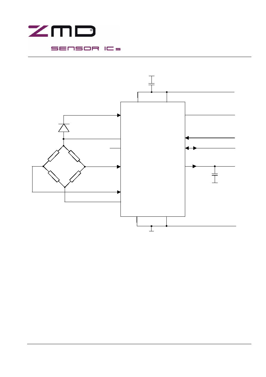
3. Application
Circuit
(*) either pin/pad may be chosen, whichever is more favourable layoutwise
VSSA VSS
VBN
VSSB
VBP VOUT
VDDB1 (*) SCL
VDDB2 (*) SDA
VDDA VDD
VTN VPP
+5V typ.
0V
Temperature
Sensing
Diode
Differential
Sensor
220nF
10 to 25nF

Datasheet, Rev. 1.4, March 27th, 2002 3/21
ZMD31020
Differential Sensor Signal Conditioner
4. Pin
Description
PIN
Number
Name
Description
1
VOUT
analog conditioned sensor signal output
2
VDDA (*)
analog device functions positive supply
3
VDD
digital device functions positive supply
4
VSS
digital device functions negative supply
5
SCL
I≤C clock input, on-chip pull-up resistor
6
SDA
I≤C data input / output, on-chip pull-up resistor
7
VPP
positive EEPROM programming voltage
8
VBN
differential sensor signal negative input
9
VDDB2 (*)
positive supply for sensor and temperature sensing diode
10
VTN
input for temperature sensing diode
11
VDDB1 (*)
positive supply for sensor and temperature sensing diode
12
VBP
differential sensor signal positive input
13
VSSB (**)
sensor negative supply
14
VSSA (**)
analog device functions negative supply
(*)
VDDA, VDDB1 and VDDB2 tied to common on-chip positive supply rail
(**)
VSSA and VSSB tied to common on-chip negative supply rail
Datasheet, Rev. 1.4, March 27th, 2002 4/21
ZMD31020
Differential Sensor Signal Conditioner
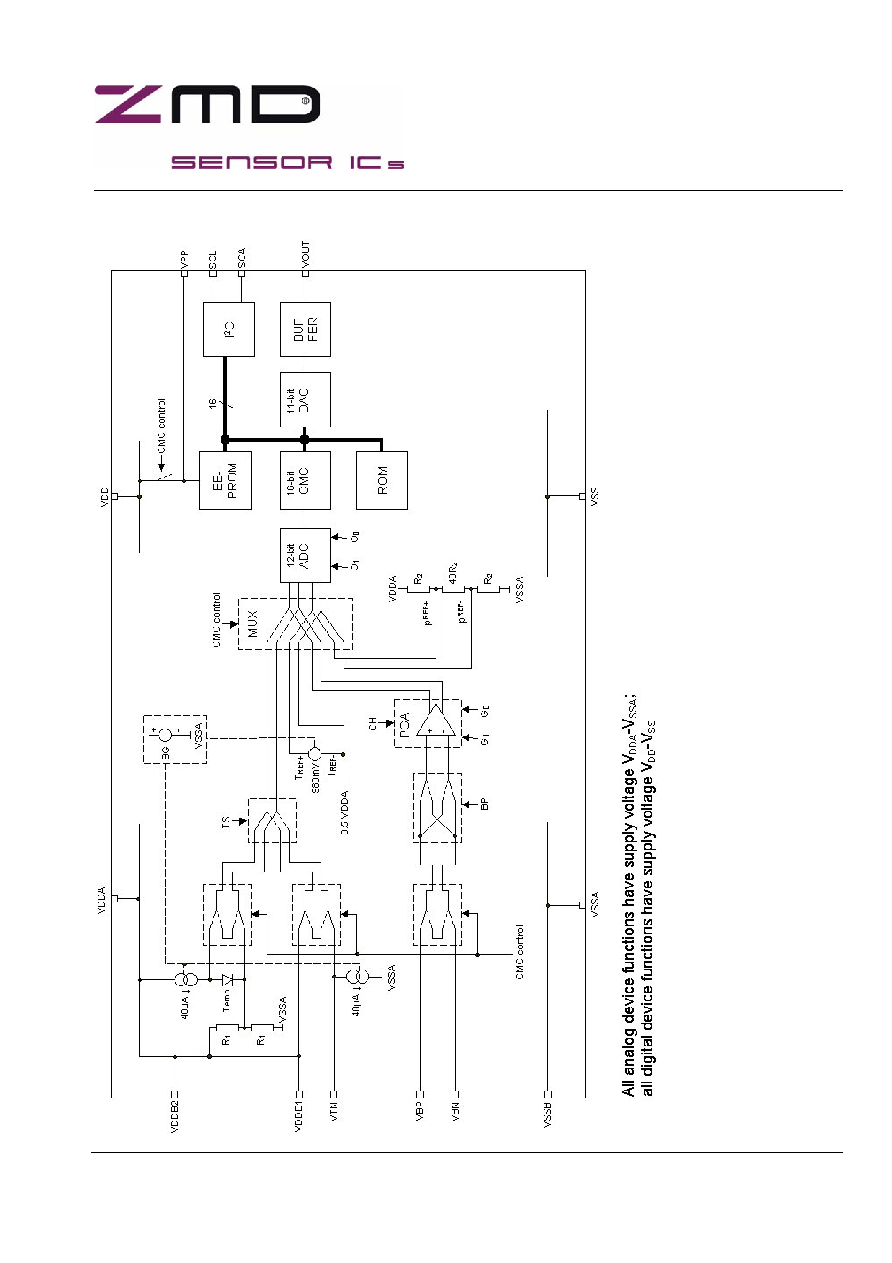
5. Block
Schematic
Datasheet, Rev. 1.4, March 27th, 2002 5/21
ZMD31020
Differential Sensor Signal Conditioner
6. Functional
Description
6.1 Configuration
Word
Many of the following sections, describing each block of ZMD31020 in detail, will refer to configuration bits, part
of the configuration word stored under address (9)hex of the parameter EEPROM, see section 6.6.
These bits are settings for a number of on-chip device functions and select specific functional or parametrical
behaviour.
As described earlier the contents of the parameter EEPROM are determined and calculated, written and stored
under PC-control during the calibration procedure. Hence the configuration bits are coded and non-volatilely
stored once calibration of a ZMD31020 device / sensor pair has taken place, and will remain unchanged during
regular sensing operation, unless re-calibration is performed.
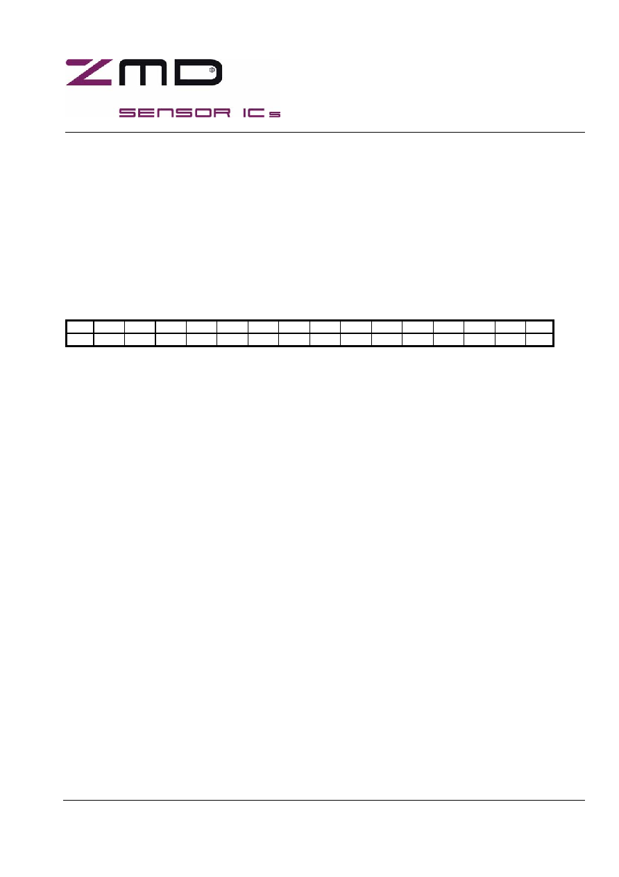
15
14
13
12
11
10
9
8
7
6
5
4
3
2
1
0
-
-
-
-
-
-
-
-
-
CH
TS
BP
G1
G0
O1
O0
Configuration word, stored under address (9)hex of the parameter EEPROM
Only 7 bits of the configuration word are relevant settings as follows:
Bit 0, Bit 1
ý
O0, O1: select ADC's output bias @ input zero
Bit 2, Bit 3
ý
G0, G1: select PGA's gain
Bit 4
ý
BP: cross-switches differential sensor inputs VBP and VBN
Bit 5
ý
TS: selects on-chip vs. off-chip temperature sensor
Bit 6
ý
CH: enables PGA's chopper-stabilization
A truth table, listing the code options of the individual configuration bit(s), is included in the section describing
the specific function which it (they) is (are) relevant for.
6.2
Differential Sensor
ZMD31020 has been specifically designed to be a signal conditioner for ratiometric differential sensors, e.g.
Wheatstone bridge type sensors.
The sensor is supplied from VDDB1 or VDDB2 (whichever pin/pad is more favourable layoutwise) at the + side
and tied to VSSB at the ≠ side. The sensor's differential output signal is routed to VBP and VBN.
A ratiometric sensor typically generates a differential output signal proportional to the supply voltage applied to
it.
Sensor and signal conditioner ZMD31020 have the same supply (see block schematic in section 5), hence the
differential input voltage seen by ZMD31020 is ratiometric to it's supply voltage.
6.3
Temperature Sensing
The transducer characteristic of a sensor tends to change with temperature.
To compensate for this, ZMD31020 is equipped to measure temperature, be it through an off-chip diode,
typically in close thermal contact with the sensor, or alternatively through an on-chip diode.