
ZR36050
August 1993
ZORAN Corporation
s
1705 Wyatt Drive
s
Santa Clara, CA 95054
s
(408) 986-1314
s
FAX (408) 986-1240
JPEG IMAGE COMPRESSION PROCESSOR
ADVANCE INFORMATION
s
Implements JPEG Baseline image compression and
expansion, including:
- DCT/IDCT operations
- Quantization
- Variable length coding/decoding
s
Full support of the JPEG Baseline standard, including:
- Bit and byte stuffing
- JPEG markers including restart (RST), application (APP),
and comment (COM)
s
JPEG Lossless compression and expansion
s
DMA/SLAVE bus interface
s
Motion video (30 frames/sec) compression/expansion
capability for CCIR resolution (720 x 480)
FEATURES
s
"Fast Preview" option
- Preview of "thumbnail" version of images (up to 25x faster)
s
Bit rate control option
- Guarantees compressed image file size
s
Low cost solution
- Low cost single chip
- Support for inexpensive memories
- Requires minimal host intervention
s
TTL compatible
s
27 and 21 MSamples/sec data-rate
s
Standby mode for very low power consumption
s
100-pin plastic quad flat-pack (PQFP) packaging
s
Computer and multimedia add-in boards
s
Full-motion video compression/expansion
s
Digital still cameras and peripherals
s
Security and industrial systems
APPLICATIONS
GENERAL DESCRIPTION
The ZR36050 is a high-speed JPEG Image Compression Pro-
cessor that performs the algorithm specified by the JPEG
Baseline and JPEG Lossless standards for high-quality image
compression and expansion of continuous-tone color or mono-
chrome images. The ZR36050 performs Discrete Cosine
Transform (DCT), quantization and variable-length encoding for
image compression (coding), and the corresponding inverse
operations for expansion (decoding).
In the JPEG Baseline encoding operation, the ZR36050
performs the DCT operation on 8 x 8 blocks of image data, con-
verting image data into its spatial frequency components, and
quantizes them using a user defined "quantization table."
Because the human visual system is less sensitive at the higher
spatial frequencies, these higher frequency components can be
quantized more coarsely than the lower-frequency components,
with negligible effect on image quality.
The coarser quantization of high-frequency coefficients results in
long strings of zero valued quantized coefficients, when the 8x8
blocks are scanned in zigzag order. The scanned coefficients
are characterized in terms of their nonzero values and the zero
run lengths. As a result, a long string of zeroes is coded as a
single number. The ZR36050 then performs Huffman coding
using user-defined Huffman tables, whereby bit patterns of dif-
ferent lengths code the nonzero values (values that occur
frequently use the shortest codes; while those that infrequently
occur use the longest codes). These techniques greatly reduce
the amount of memory needed to store an image.
In the decoding operation, the compressed data is decoded (the
inverse of the Huffman and the zigzag modified-run-length
coding), and dequantized. A 2-D inverse Discrete Cosine Trans-
form is performed on the DCT coefficients, resulting in an
expanded image.
Figure 1. ZR36050 Logical Pinout
CWE
WR
CCS
CS
12
PIXEL
DSYNC
COMP
RESET
STDBY
FREEZE
END
STOP
CL
ZR36050
JPEG IMAGE
COMPRESSION
PROCESSOR
Host Interface
Compressed
Data Interface
PIXEL
Interface
Control
2
EOS
CLK_IN
COE
CODE
CAEN
CBUSY
DATA
ADDR
INT
DINT
DREQ
VSS
+5V
CSYNC
RD
DACK
CLKEN
DCT
Coefficient
Output
Clock
COEF
11
8
8
10
s
Videophones and color FAX machines
s
Color printers and scanners
s
Fixed bit rate image transmission devices
s
Cost-sensitive image compression systems
This document was created with FrameMaker 4.0.4

ZR36050
2
ADVANCE INFORMATION
In addition to the JPEG Baseline, the ZR36050 supports a
subset of JPEG Lossless standard. The ZR36050 performs one
dimensional differential prediction followed by variable-length
encoding for JPEG Lossless compression, and the correspond-
ing inverse operations for JPEG Lossless expansion.
The ZR36050 maintains full compatibility with the JPEG
Baseline standard. The unique ability to perform bit rate control.
Bit rate control capability allows the user to preset the size of a
compressed image file. This capability is important because
without bit rate control, the size of a compressed image is highly
data dependent for a given set of quantization tables (images
with fine detail generate considerably larger files than files gen-
erated from smooth images).
The ability to perform bit rate control is critical for applications
where predictable file sizes for compressed images is desired, or
where the time allocated to transmit an image across a commu-
nications network is fixed. The compressed image file size is
constrained to be no greater than a user specified target, and is
typically kept within a range of 95% to 100% of this target. The
bit rate control feature relies on a two pass algorithm for its
operation.
The ZR36050 has the ability to generate a "thumbnail" version of
an image for "Fast Preview." This thumbnail image is a 1/64
scale version of the image, and is generated up to 25 times
faster than full image expansion. The thumbnail image is gener-
ated from the JPEG Baseline compressed data, and eliminates
the need for a separately encoded and stored thumbnail image.
This feature is particularly useful for previewing large databases
of images.
The ZR36050 operates as a dedicated processor requiring only
minimal host intervention. The host processor controls the oper-
ation of the device by writing parameter values into the
ZR36050's Internal Memory. Once initialized, the ZR36050
operates continuously until it has completed the compression or
expansion of the image. Since the ZR36050 fully complies with
the JPEG Baseline standard, the compressed data bit-stream
generally requires no intervention by the host. Full JPEG capa-
bility also allows for the interchange of files created by other
JPEG imaging systems with files generated by systems using
the ZR36050.
The ZR36050 is useful for a wide range of motion and still video appli-
cations. For example, a typical multimedia application (30 seconds of
video at 10 frames/sec and 320 x 240 resolution) would require 69
Mbytes of storage in uncompressed form. With compression using the
ZR36050, the requirement can be reduced to 2.9 Mbytes, making
storage feasible on a personal computer hard disk. Similarly, for digital
still camera applications, the memory requirement can be reduced
from a 22 Mbyte hard disk to a 1 Mbyte memory card for storage of
twenty 768 x 480 compressed images.
The ZR36050 is fabricated with an advanced low-power CMOS
technology, making it suitable for use in low-power, cost-sensi-
tive applications. The device is available in a 100-pin Plastic
Quad Flat Pack (PQFP).
ZR36050
3
ADVANCE INFORMATION
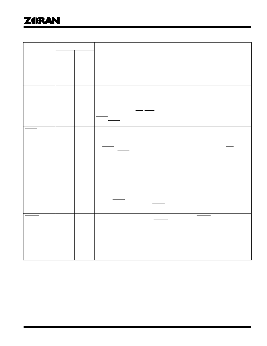
Table 1. Signal Description
1, 2
Signal
Type
3
Description
Encode
Decode
VCC
S
S
+5 volt Power supply. All VCC pins must be connected to +5V.
VSS
S
S
Ground. All VSS pins must be connected to GND.
CLK_IN
I
I
Data Transfer Clock. Provides data transfer timing for the device. All timing is referenced to the rising
edge of this clock.
RESET
I
I
Reset. This active-low input signal resets all the internal controls and places the ZR36050 in the Idle
state. RESET can be activated only when CLKEN is asserted and must remain active for a minimum
of four CLK_IN cycles.
The STATUS_0, INT_REQ_0, and INT_REQ_1 register bits are reset by this signal. The STATUS_1
bits except the END bit are reset; the END bit is set. RESET initializes the ZR36050 to the compres-
sion mode, and activates END, STOP and COMP.
RESET can be activated during the Standby state; in this case the device draws normal current as
long as RESET is active.
STDBY
I
I
Standby. This active-low input signal places the ZR36050 in the Standby state. If CLKEN is active,
only the internal clock circuit consumes power. If CLKEN is inactive in the Standby state, the device
power consumption is further reduced.
The ZR36050 should be switched to the Standby state only when it is in the Idle state: after activation
of a RESET and prior to loading the Internal Memory, or after the ZR36050 issues an END. If CLKEN
is active, then STDBY should be deasserted at least four CLK_IN cycles before accessing the Internal
Memory.
RESET can be activated during the Standby state, only when CLKEN is active. Reading from or
writing to the Internal Memory during the Standby state is prohibited.
CLKEN
I
I
Clock Enable. This active-high input signal enables the data transfer clock CLK_IN, and the internal
PLL that generates an internal double-frequency clock. When inactive, this signal reduces power
further in the Standby state by deactivating the internal clock. The frequency of CLK_IN must be
stable before CLKEN is activated. Furthermore, 5000 CLK_IN cycles are required for the PLL to sta-
bilize, after CLKEN has been activated and before the device is ready for operation.
If the frequency of CLK_IN is changed without turning off the power, then CLKEN must be reactivat-
ed. When STDBY is high, this pin should also be high. For systems in which the 5000 CLK_IN
recovery time is not significant, the STDBY and CLKEN pins can be tied together to the external
standby signal.
FREEZE
I
I
Freeze. This active-low input signal freezes all chip operations. FREEZE is sampled on the rising
edge of CLK_IN. Immediately after FREEZE is sampled, all buses float and all activities of the
ZR36050 are frozen in their current state. All activities resume normally following the deassertion of
FREEZE.
END
O
O
End Of Process. This active-low output signal indicates the normal end of an encoding or decoding
process. If an encoding process ends because of an overflow, END is not activated.
END is activated after activation of RESET and at the completion of an encoding or decoding
process. It stays activated until a GO command is issued or the STATUS_1 register in the Internal
Memory is read.
1. The DATA, CODE, PIXEL, and COEF buses have internal pull-downs that provide 50 microamps of pull-down current at 0.4 volts.
2. The control pins: DSYNC, EOS, STOP, END, CL, CSYNC, COE, CWE, CCS, CAEN, INT, DINT, DREQ and COMP, have internal pull-up
devices that provide 50 microamps at 2.4 volts. These pull-ups are turned on only when STDBY is active but RESET is inactive. When STDBY
is active together with RESET, the above control pins float.
3. I = Input, O = Output, B = Bidirectional, S = Supply.

ZR36050
4
ADVANCE INFORMATION
CL(1-0)
-
O
Color. During the decoding mode, the CL output signals designate the index of the color component
that is being decoded.
00 - First MCU component.
01 - Second MCU component.
10 - Third MCU component.
11 - Fourth MCU component or Idle.
In the JPEG Baseline mode, the designation changes with the falling edge of the first DSYNC of the
component or with the falling edge of EOS.
In the Fast Preview and Lossless decoding modes, CL is active together with the DSYNC which
precedes the DC coefficient value and the pixel data, respectively.
CL is undefined in the encoding mode.
STOP
O
I
Stop Sending/Receiving. This active-low bidirectional signal is an input in encoding and output in
decoding modes. STOP is used for the following purposes:
At the start of and during an encoding operation, STOP is an output signal indicating that the
ZR36050 is not ready to receive image data. STOP is activated when the ZR36050 is in the Idle state,
and when reading or processing Internal Memory parameters during the encoding modes.
In the encoding mode, STOP is an output signal indicating that three of the ZR36050's four internal
coefficient buffers are full. In this case, STOP is output 42 CLK_IN cycles prior to the last image data
sample of the current block that is being input. If STOP remains active until the next DSYNC is due,
then the system must not input the next DSYNC and the image data block. STOPs that are deacti-
vated prior to the next DSYNC can be ignored. The system can resume inputting the next image data
block immediately after STOP is deactivated.
In the Lossless encoding mode, the system must stop inputting data within three CLK_IN cycles of
activation of STOP to prevent overflow.
In the decoding mode, STOP is an input signal that notifies the ZR36050 that it should not assert the
next DSYNC and consequently delay output of the next decoded image data block at the end of the
current block. In this case, STOP must be activated at least 24 CLK_IN cycles before the last image
sample of the current block that is being output and must remain active at least until the end of the
current block. Once STOP is deactivated, the ZR36050 outputs the next DSYNC followed by its cor-
responding image data block, at least 17 CLK_IN cycles after deactivation of STOP.
In the Lossless decoding and Fast Preview modes, when STOP is activated or deactivated, the
ZR36050 stops or resumes delivering image data after 2 CLK_IN cycles.
PIXEL(11-0)
I
O
Pixel bus. This 12-bit unsigned bidirectional bus is used for the following purposes:
In the encoding modes, the most significant 8 bits are used to carry the input image data. The remain-
ing 4 bits are "don't care" and can be left as unconnected pins.
In the Lossless encoding mode, it is a 12-bit input bus. If fewer than 12 bits are required, then the
most significant bits of the bus are used to carry the input image data.
In the decoding mode, the most significant 8 bits are used to carry the output image data. The least
significant 4 bits are forced to "0".
In the Lossless decoding mode, this is a 12-bit output bus. If fewer than 12 bits are used, then the
most significant bits of the bus are used to carry the output image data and the unused bits are forced
to "0".
In the Fast Preview mode, it is an output bus carrying the 11-bit unsigned DC coefficient values on
the most significant 11 bits of the bus. The least significant bit is forced to "0".
The input/output data in the encoding and decoding modes is ordered in row-by-row scanned 8x8
blocks. In the Lossless encoding and decoding modes, the image data is scanned row by row.
Table 1. Signal Description
1, 2
(Continued)
Signal
Type
3
Description
Encode
Decode
1. The DATA, CODE, PIXEL, and COEF buses have internal pull-downs that provide 50 microamps of pull-down current at 0.4 volts.
2. The control pins: DSYNC, EOS, STOP, END, CL, CSYNC, COE, CWE, CCS, CAEN, INT, DINT, DREQ and COMP, have internal pull-up
devices that provide 50 microamps at 2.4 volts. These pull-ups are turned on only when STDBY is active but RESET is inactive. When STDBY
is active together with RESET, the above control pins float.
3. I = Input, O = Output, B = Bidirectional, S = Supply.

ZR36050
5
ADVANCE INFORMATION
DSYNC
I
O
Data Synchronization. This active- low signal is an input in encoding and output in decoding modes.
In the encoding modes, DSYNC marks the start of an 8x8 image data block and should appear as an
input one CLK_IN before the first image data of a block. In the decoding modes, DSYNC is output
one CLK_IN before the first image data sample of a block. The width of DSYNC is one CLK_IN cycle.
In the Fast Preview mode, and the Lossless encoding and decoding modes, this signal precedes
each image data sample.
EOS
I
O
End Of Scan. This active-low signal is an input in encoding modes. EOS indicates the last image data
sample of each scan entering the ZR36050. In encoding modes, EOS must be input regardless of the
STOP signal.
EOS is an output signal in the decoding mode. It is generated together with the last image data
sample of each scan leaving the ZR36050. In this case, DSYNC will not be issued.
In the Fast Preview and Lossless decoding modes, EOS is output within 64 CLK_IN cycles after the
last sample of a scan. It is merely used in as an indication of the completion of the current process
without having any timing significance.
In decoding mode, EOS is output regardless of the STOP signal.
The width of EOS is one CLK_IN cycle.
COEF(10-0)
O
O
Coefficient Bus. This 11-bit output bus is used to transfer DCT coefficients out of the device in the
encoding and decoding modes. The DCT coefficients are output in column-major order. This bus is
not used in the Fast Preview and Lossless encoding and decoding modes.
CSYNC
O
O
Coefficient Synchronization. This active-low signal indicates the beginning of an 8x8 DCT coefficient
block.
In the encoding and decoding modes, this signal is generated by the ZR36050. It is asserted one
CLK_IN cycle before the first coefficient of a block is placed on the COEF bus by the ZR36050. The
width of CSYNC is one CLK_IN cycle.
CSYNC is not used in the Fast Preview and Lossless encoding and decoding modes.
CODE(7-0)
O
I
Code. In Master mode Compressed Data Transfer, this 8-bit bidirectional bus is used to read the com-
pressed data from or write to the Compressed Data Memory.
In the 16-bit Slave and DMA modes, this bus is used as an extension of the DATA bus.
COE
-
O
Compressed Data Memory Read. This active-low output signal acts as a read pulse from the
ZR36050 to the Compressed Data Memory. COE goes active 0.5 CLK_IN cycles after the start of a
read cycle and remains active until the end of the read cycle. The CODE bus is latched on the rising
edge of COE.
CWE
O
-
Compressed Data Memory Write. This active-low output signal acts as a write pulse from the
ZR36050 to the Compressed Data Memory. CWE goes active 0.5 CLK_IN cycles after the start of a
write cycle and remains active until the end of the write cycle.
CCS
O
O
Compressed Data Memory Chip Select. This active-low output signal acts as a chip select signal from
the ZR36050 to the Compressed Data Memory. CCS goes active at the start of a read or write cycle
and remains active throughout the cycle. CCS remains active continuously in back to back read or
write cycles. The length of a read or write cycle can be from one to eight CLK_IN periods.
CAEN
O
O
Address Counter Enable. This active-low output signal can be used to advance an external Com-
pressed Data Memory address counter.
Table 1. Signal Description
1, 2
(Continued)
Signal
Type
3
Description
Encode
Decode
1. The DATA, CODE, PIXEL, and COEF buses have internal pull-downs that provide 50 microamps of pull-down current at 0.4 volts.
2. The control pins: DSYNC, EOS, STOP, END, CL, CSYNC, COE, CWE, CCS, CAEN, INT, DINT, DREQ and COMP, have internal pull-up
devices that provide 50 microamps at 2.4 volts. These pull-ups are turned on only when STDBY is active but RESET is inactive. When STDBY
is active together with RESET, the above control pins float.
3. I = Input, O = Output, B = Bidirectional, S = Supply.