 | –≠–ª–µ–∫—Ç—Ä–æ–Ω–Ω—ã–π –∫–æ–º–ø–æ–Ω–µ–Ω—Ç: 5100- | –°–∫–∞—á–∞—Ç—å:  PDF PDF  ZIP ZIP |
5100-Series IF-Band and L-Band Fiber-Optic Links
Data Sheet, Rev. 1
September 2001
Features
s
10 MHz to 200 MHz
s
950 MHz to 2050 MHz
s
Up to eight plug-in cards per 3U chassis
s
Up to four flange-mount modules per 1U chassis
s
Redundant power supplies for 3U chassis
s
Affordable replacement for coaxial systems
Applications
s
TVRO
s
Broadcast
s
Earth stations
s
Headends
s
VSAT
s
GPS
s
Radios
Description
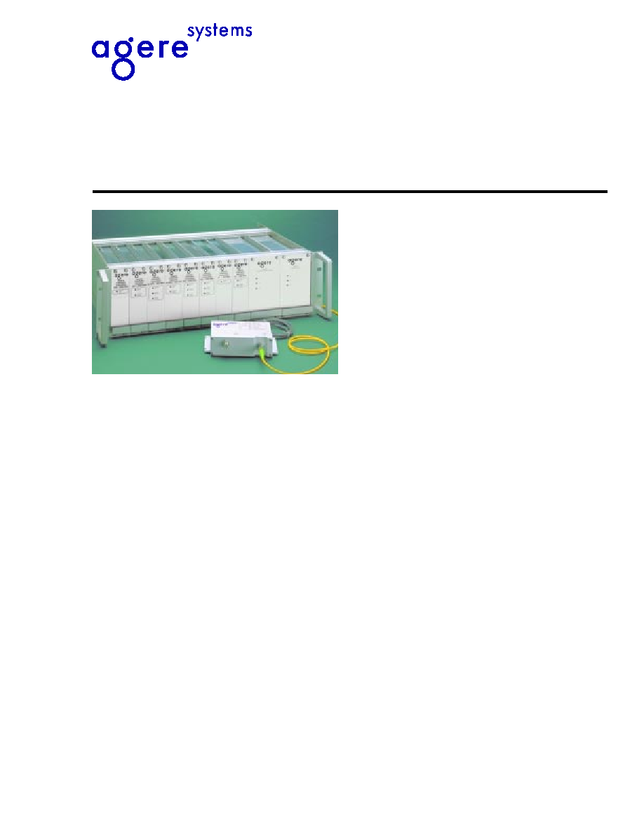
The 5100-Series fiber-optic interfacility links (IFLs)
are a high-performance, cost-effective alternative to
coaxial cable for 10 MHz to 200 MHz IF-band and
950 MHz to 2050 MHz L-band satellite communica-
tions applications.
Agere Systems Inc. fiber-optic IFLs function as a
transparent link between a satellite antenna and
receiver equipment. These IFLs eliminate the limita-
tions of copper systems by enabling longer transmis-
sion distances while retaining the highest level of
signal quality.
In addition, Agere Systems' fiber optics provide sev-
eral other significant network advantages, including
simplified network design, ease of installation, and
immunity from EMI/RFI and lightning. They are avail-
able either as a flange-mount enclosure for outdoor
applications or as a plug-in for integration with Agere
Systems' System 10000 rack-mount chassis.
2
Data Sheet, Rev. 1
5100-Series IF-Band and L-Band Fiber-Optic Links
September 2001
Agere Systems Inc.
Maximum Ratings
Stresses in excess of the absolute maximum ratings can cause permanent damage to the device. These are abso-
lute stress ratings only. Functional operation of the device is not implied at these or any other conditions in excess
of those given in the operational sections of the data sheet. Exposure to absolute maximum ratings for extended
periods can adversely affect device reliability.
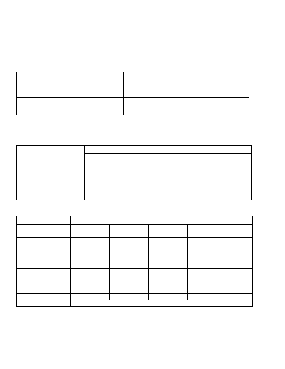
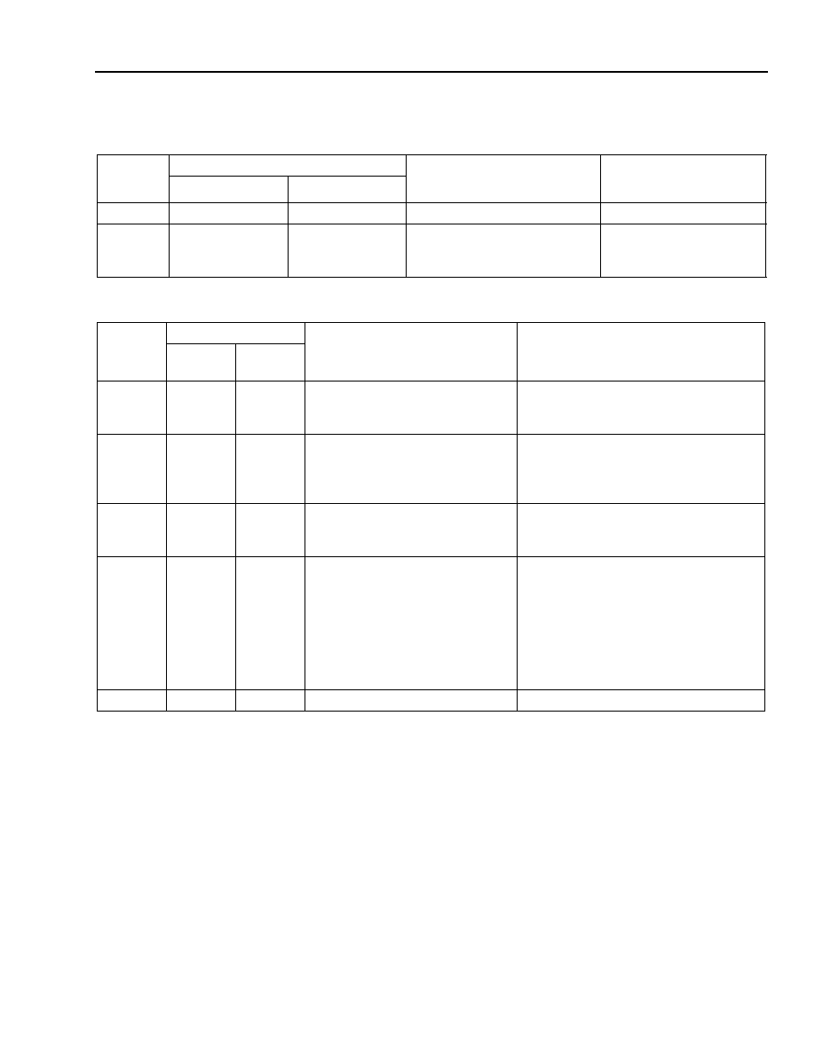
Characteristics
Parameter
Symbol
Min
Max
Unit
Operating Temperature Range:
Flange-mount
Plug-in
T
OP
≠40
0
60
50
∞C
∞C
Storage Temperature Range:
Flange-mount
Plug-in
Tstg
≠45
≠45
85
85
∞C
∞C
Table 1. Frequency and Package Options
Frequency
Range
Transmitters
Receivers
Flange Mount
Plug-in
Flange Mount
Plug-in
IF-Band:
10 MHz--200 MHz
3120A
10357A
4120A
10457A
L-Band:
950 MHz--1450 MHz
950 MHz--1750 MHz
950 MHz--2050 MHz
3110A
3111A
3112A
10346A
10346B
10347A
4110A
4111A
4112A
10446A
10446B
10447A
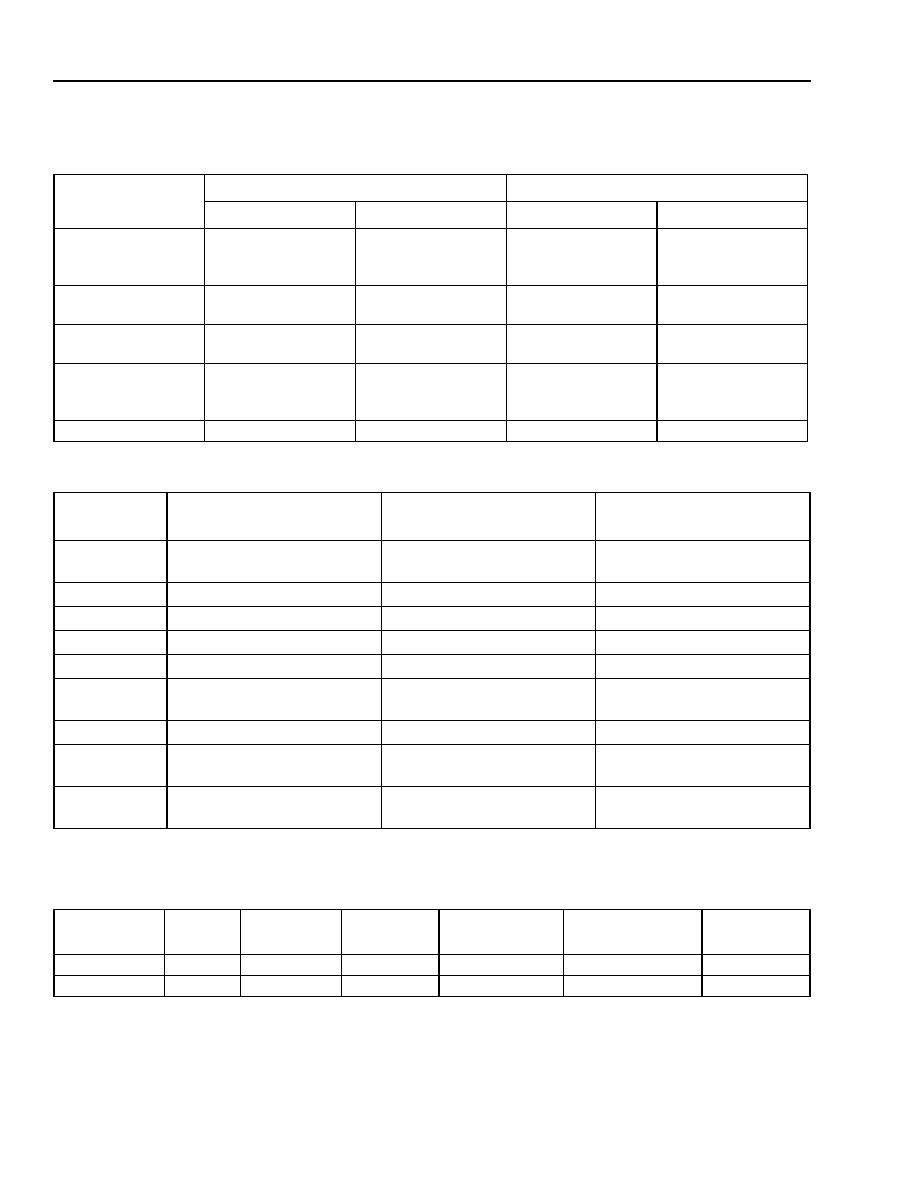
Table 2. IF Band Performance (For complete link of Tx, Rx, 1 dB optical loss, and >60 dB optical return loss.)
Parameter
IF Band Performance
Unit
Tx Gain Option
Std.
≠102 (low)
≠102 (low)
Std.
--
Rx Gain Option
Std.
≠102 (high)
Std.
≠102 (high)
--
Gain (at 25 ∞C), Min
0
0
≠15.0
15.0
dB
Amplitude Flatness:
10 MHz--200 MHz
Any 40 MHz
±0.5
±0.25
±0.5
±0.25
±0.5
±0.25
±0.5
±0.25
dB
dB
Noise Figure, Max
28
43
43
28
dB
Output IP3, Min
0
9
0
9
dBm
Output 1 dB Compres-
sion, Min
≠10 0 ≠10 0
dBm
VSWR, In and Out
1.5:1
1.5:1
1.5:1
1.5:1
--
Max. RF Input (Tx)
≠8
7
7
≠8
dBm
In/Out Impedance
75 BNC, female (50 BNC, option ≠101)
3
Agere Systems Inc.
Data Sheet, Rev. 1
September 2001
5100-Series IF-Band and L-Band Fiber-Optic Links
Characteristics
(continued)
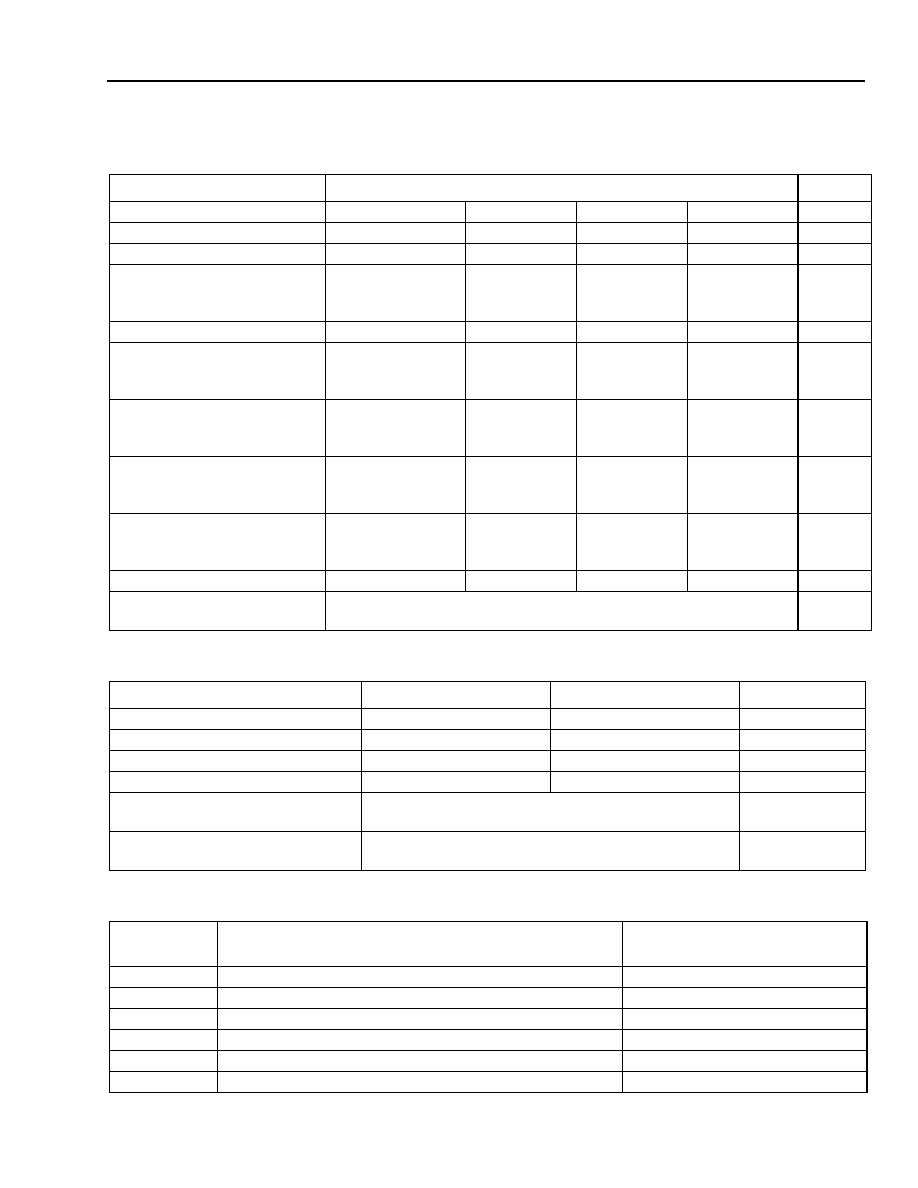
Table 3. L-Band Performance (For complete link of Tx, Rx, 1 dB optical loss, and >60 dB optical return loss.)
Parameter
L-Band Specification
Units
Tx Gain Option
Std.
≠002 (high)
Std.
≠002 (high)
--
Rx Gain Option
Std.
≠002 (low)
≠002 (low)
Std.
--
Gain (at 25 ∞C), Min
≠4.0
≠4.0
≠21.0
13.0
dB
Amplitude Flatness:
Any 500 MHz
Any 40 MHz
±1.5
±0.35
±1.5
±0.35
±1.5
±0.35
±1.5
±0.35
dB
dB
Noise Figure, Max
45
28
45
28
dB
Input IP3, Min:
Tx to ≠20 ∞C
Tx to ≠40 ∞C
7.5
4.5
≠9.5
≠12.5
7.5
4.5
≠9.5
≠12.5
dBm
dBm
Input 1 dB Compression (typ):
Tx to ≠20 ∞C
Tx to ≠40 ∞C
0
≠3
≠17
≠20
0
3
≠17
≠20
dBm
dBm
Gain vs. Temp. (typ):
Tx
Rx
0.09
0.06
0.12
0.03
0.09
0.03
0.12
0.06
dB/∞C
dB/∞C
VSWR:
Tx (input)
Tx (output)
2.0:1
1.8:1
2.0:1
1.8:1
2.0:1
1.8:1
2.0:1
1.8:1
--
--
Max. RF Input (Tx)
3
≠14
3
≠14
dBm
In/Out Impedance
75 F-type, female
(50 SMA, Option -001)
Table 4. Optical Characteristics
Parameter Transmitter
Receiver
Unit
Wavelength
1310 ± 30
--
nm
Power
1.10 ± 0.3
--
mW
Laser dc Modulation Gain
0.02
--
W/A
dc Responsivity
--
0.75
A/W
Fiber
Single-mode, 9
µ
m/125
µ
m,
(
SMF-28
TM or equivalent)
µ
m
Connector
Optical Return Loss
FC/APC Tight Fit (Seikoh Giken or equivalent),
60
--
dB
Table 5. Mounting Options
Part/Model
Number
Description
Capacity
1260-001-001
NEMA Enclosure (12 in. x 12 in. x 4 in.)
Up to two flange-mount modules
1261-001-001
1U, 19 in. Rack-mount Chassis (1.75 in.x 19 in. x 18 in.)
Up to four flange-mount modules
1261-002-001
1U, 19 in. Rack-mount Chassis and Internal Power Supply
Up to four flange-mount modules
10990A
3U, 19 in. Rack Mount Chassis
Up to eight plug-in modules
10901A
3U, Plug-in Power Supply (90 Vac--260 Vac input)
--
10901B
3U, Auxiliary Plug-in Power Supply (90 Vac--260 Vac input)
--
4
Data Sheet, Rev. 1
5100-Series IF-Band and L-Band Fiber-Optic Links
September 2001
Agere Systems Inc.
Characteristics
(continued)
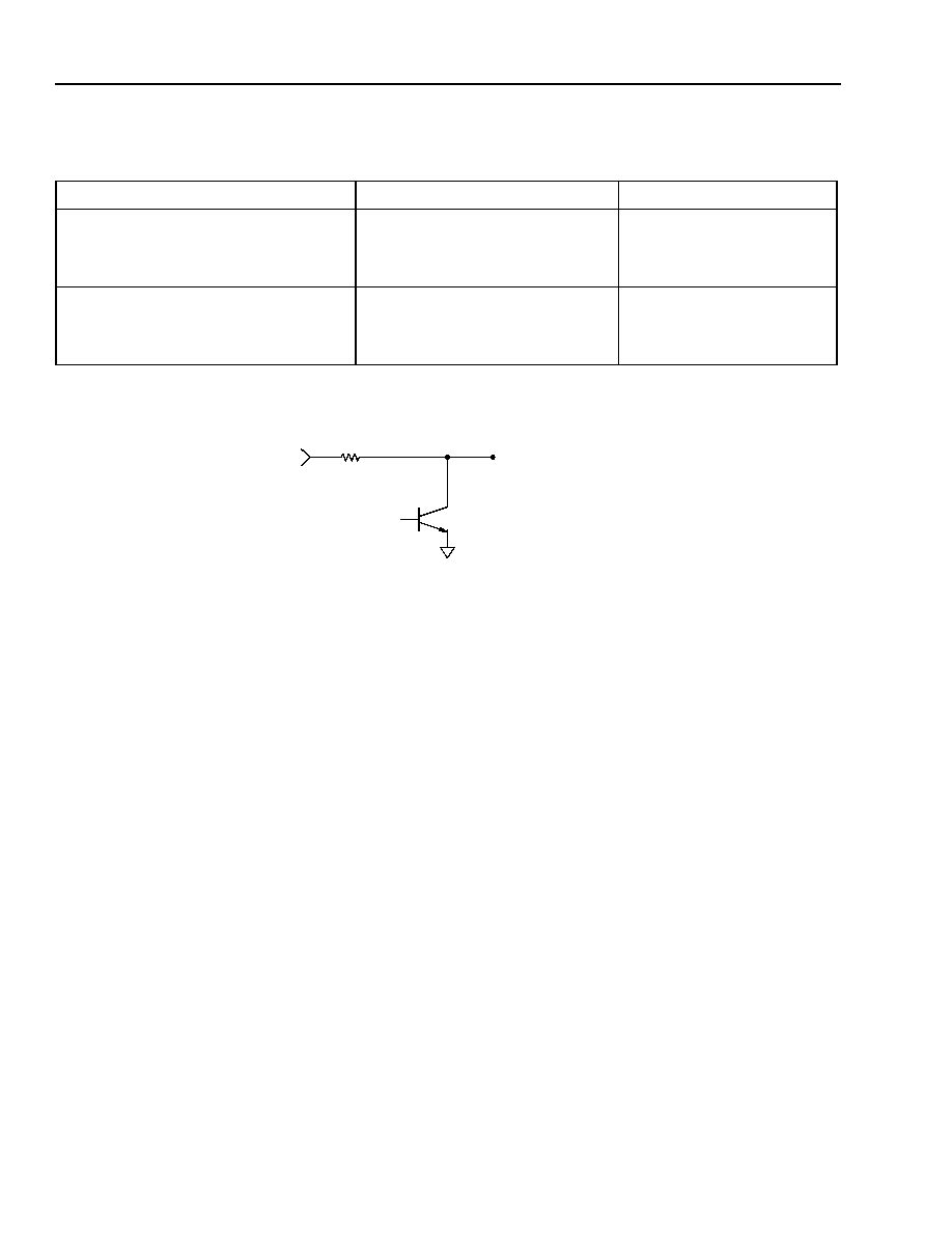
Figure 1. Receiver Electrical Schematic
Table 6. Device Resistance and Voltage
Parameter
Specification
Unit
Resistance:
L-band Tx/Rx
IF Rx
IF Tx
1000
825
432
Voltage (V
CC
):
L-band Tx/Rx
IF Rx
IF Tx
5
10
6.5
V
V
V
V
CC
R
OPEN IF <0.1 mW (APPROX.);
SINKS <10 mA IF >0.1 mW
ALARM
(R
X
OPTICAL
POWER)
1-1188(F)
5
Agere Systems Inc.
Data Sheet, Rev. 1
September 2001
5100-Series IF-Band and L-Band Fiber-Optic Links
Options
Table 7. IF-Band Options
Option
Option Availability
Description
Standard Configuration
Flange Mount
Plug-in
-101
x
x
50
BNC, Female.
75
BNC, Female.
-102
x
x
For Higher Signal Input.
Tx: Single-stage Amp.
Rx: Two-stage Amp.
--
Tx: Two-stage Amp.
Rx: Single-stage Amp.
Table 8. L -Band Options
Option
Option Availability
Option Description
Standard Configuration
Flange-
Mount
Plug-in
-001
x
x
50
SMA, Female.
75
F-type Connector, Female.
-002
x
x
For Lower Signal Input.
Tx: Two-stage Amplifier.
Rx: Single-stage Amplifier.
.
Tx: Single-stage Amplifier.
Rx: Two-stage Amplifier.
-003
x
--
Unit to Run from
5.0 V ± 0.2 V.
No Internal dc Regulator.
Internal dc Regulator Operates
from 8 V to 24 V Input.
-004
x
--
RF Connector Is ac Coupled, with
No dc on Center Pin.
Flange-mount Tx and Rx:
RF Connects to dc Input, so dc on RF
Connector Is ac (caution is needed to
avoid shorting).
Tx Plug-in: dc Voltage Can Be Coupled
on RF Connector with Field-config-
urable Jumper.
Rx Plug-in: RF Connector Is ac Coupled.
-006
--
x
75
CANARE BNC, Female.
75
F-Type Connector, Female.
6
Data Sheet, Rev. 1
5100-Series IF-Band and L-Band Fiber-Optic Links
September 2001
Agere Systems Inc.
Package Information
1. Powered from 10901A, 10901B, or equivalent power supply.
2. Accessible via connector on back panel of 10990A chassis.
1. Ripple and noise: 100 mVp-p >100 kHz; 20 mVp-p <100 kHz.
2. 15 V may be from model 10901A or B power supplies
.
Table 9. Flange-Mount dc Leads
Lead Color
IF-Band
L-Band
Tx
Rx
Tx
Rx
Red
dc Input
12 V--24 V
dc Input
12 V--24 V
8 V--24 V
Connects to RF
Center Pin
8 V--24 V
Connects to RF
Center Pin
Brown
Not Used
Low Optical Power
Alarm
Not Used
Low Optical Power
Alarm
Orange
dc Power Monitor
for LED, etc.
dc Power Monitor
for LED, etc.
dc Power Monitor
dc Power Monitor
Yellow
Not Used
Photodiode Current
Monitor
1 V/mA
Not Used
Photodiode Current
Monitor
Black
GND
GND
GND
GND
Table 10. Model 10990A 3U Chassis and Plug-In
Plug-in
D-sub
Tx Plug-In,
IF-Band
Tx Plug-In,
L-Band
Rx Plug-In,
IF or L-Band
1
1
dc Input
Typ. 15 V
Typ. 15 V
Typ. 15 V
2
1
NC
NC
NC
3
1
NC
NC
NC
4
1
GND
GND
GND
5
2
GND
GND
GND
6
2
NC
NC
Photodiode Current
Monitor (1 V/mA)
7
2
NC
NC
Low Optical Power Alarm
8
2
NC
Same as Pin 1. Can be Jum-
pered to Pin 9.
NC
9
2
NC
Connects to RF Center Pin for
Powering LNB.
NC
Table 11. Maximum Current
1
(Applies to All Versions Except -003)
Input
Voltage
8 V
(L-Band)
12 V
15 V
2
18 V
24 V
Unit
Tx
250
170
135
115
85
mA
Rx
200
150
120
100
75
mA
7
Agere Systems Inc.
Data Sheet, Rev. 1
September 2001
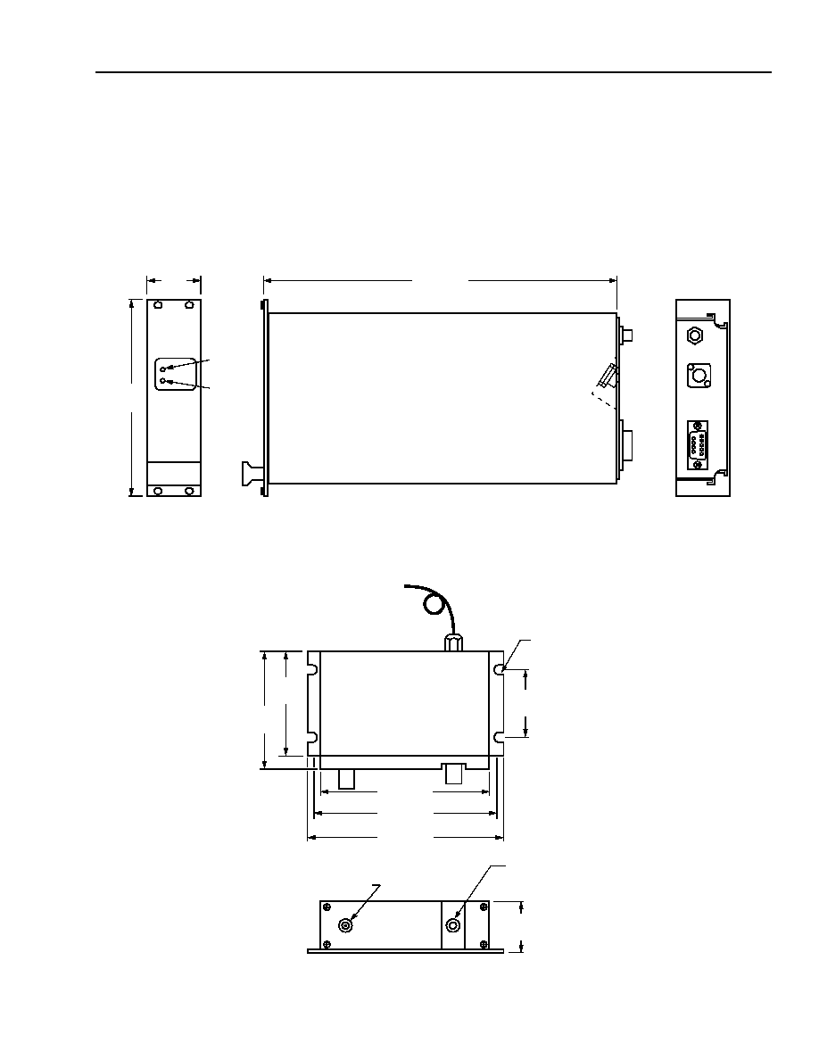
5100-Series IF-Band and L-Band Fiber-Optic Links
Outline Drawings
Dimension are in inches and (millimeters).
10457A Fiber-Optic Receiver
Flange-Mount Package
POWER
ON
OPTICAL
POWER
9.12 (232)
5.06
(129)
1.39
(35)
10457A
FIBER-OPTIC
RECEIVER
10 MHz--200 MHz
FRONT
PANEL
RF
OPTICAL
1-1189(F)
4.45 (113)
5.08 (129)
5.29 (134)
1.80
(46)
2.88
(73)
2.40
(61)
RF CONNECTOR
1.41
(36)
OPTICAL
CONNECTOR
FC/APC
0.13 DIA SLOTTED
FOR #6 SCREW
1-1190(F)
8
Data Sheet, Rev. 1
5100-Series IF-Band and L-Band Fiber-Optic Links
September 2001
Agere Systems Inc.
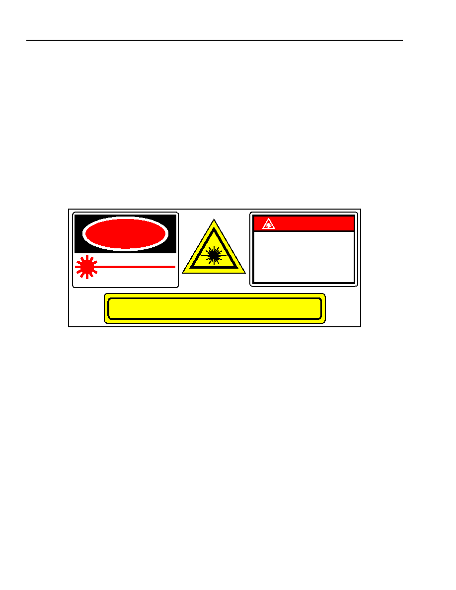
Laser Safety Information
Class IIIb Laser Product
FDA/CDRH Class IIIb laser product. All 5100 Series transmitter versions are Class IIIb laser products per CDRH,
21 CFR 1040 Laser Safety requirements. All versions are Class 3B laser products per
IEC
Æ
60825-1:1993. The
device has been classified with an FDA under accession number to be determined.
This product complies with 21 CFR 1040.10 and 1040.11.
Wavelength = 1300 nm
Maximum power = 30 mW
Product is not shipped with power supply.
Caution: Use of controls, adjustments, and procedures other than those specified herein may result in
hazardous laser radiation exposure.
DANGER
INVISIBLE LASER RADIATION
IS EMITTED FROM THE END
OF FIBER OR CONNECTOR
Avoid direct exposure to beam
Do not view beam directly with
optical instruments
INVISIBLE LASER RADIATION EMITTED FROM END OF FIBER OR CONNECTOR
Avoid exposure to beam
Class 3B Laser Product IEC-60825M 1993 Max. Output: 10 mW
Wavelength: 1.3
µ
m
D A N G ER
Wavelength: 1.3
µ
m
Class IIIb Laser Product
Max. Output: 30 mW
IN VIS IB LE LA SE R R A D IATION
AVO ID D IR E C T EX PO S U R E TO B EA M

9
Agere Systems Inc.
Data Sheet, Rev. 1
September 2001
5100-Series IF-Band and L-Band Fiber-Optic Links
Ordering Information
* For additional ordering information, please contact an account manager at Agere Systems, OPTO West, 1-800-362-3891 (for sales staff,
please press option 2).
Table 12. Ordering Information*
Device Code
Description
Comcode
5100 Series
IF-Band and L-band Fiber-Optic Links
TBD

Data Sheet, Rev. 1
5100-Series IF-Band and L-Band Fiber-Optic Links
September 2001
Agere Systems Inc. reserves the right to make changes to the product(s) or information contained herein without notice. No liability is assumed as a result of their use or application.
Copyright © 2001 Agere Systems Inc.
All Rights Reserved
September 2001
DS00-299OPTO-1 (Replaces DS00-299OPTO)
For additional information, contact your Agere Systems Account Manager or the following:
INTERNET:
http://www.agere.com
E-MAIL:
docmaster@agere.com
N. AMERICA:
Agere Systems Inc., 555 Union Boulevard, Room 30L-15P-BA, Allentown, PA 18109-3286
1-800-372-2447, FAX 610-712-4106 (In CANADA: 1-800-553-2448, FAX 610-712-4106)
ASIA:
Agere Systems Hong Kong Ltd., Suites 3201 & 3210-12, 32/F, Tower 2, The Gateway, Harbour City, Kowloon
Tel. (852) 3129-2000, FAX (852) 3129-2020
CHINA: (86) 21-5047-1212 (Shanghai), (86) 10-6522-5566 (Beijing), (86) 755-695-7224 (Shenzhen)
JAPAN: (81) 3-5421-1600 (Tokyo), KOREA: (82) 2-767-1850 (Seoul), SINGAPORE: (65) 778-8833, TAIWAN: (886) 2-2725-5858 (Taipei)
EUROPE:
Tel. (44) 7000 624624, FAX (44) 1344 488 045
SMF-28
is a trademark of Corning Incorporated.
IEC
is a registered trademark of The International Electrotechnical Commission.