 | –≠–ª–µ–∫—Ç—Ä–æ–Ω–Ω—ã–π –∫–æ–º–ø–æ–Ω–µ–Ω—Ç: ICM532B | –°–∫–∞—á–∞—Ç—å:  PDF PDF  ZIP ZIP |

ICM532B CIF Color CMOS Sensor with USB Output
Data Sheet, V 1.1 November, 2002
©2000, 2001,2002 IC Media Corporation & IC Media Technology Corp
11/21/2002
page 1
Company
Confidential
ICM532B
CIF Color CMOS Image Sensor
With USB Output
Data Sheet
V1.1
November, 2002
IC Media Corporation
545 East Brokaw Road
San Jose, CA 95112, U.S.A.
Phone: (408) 451-8838
Fax: (408) 451-8839
Email: Sales@IC-Media.Com
Web Site:
www.ic-media.com
IC Media Technology Corporation
6F, No. 61, ChowTze Street., NeiHu District
Taipei, Taiwan, R.O.C.
Phone: 886-2-2657-7898
Fax: 886-2-2657-8751
Email: Ap.Sales@IC-Media.Com.tw
Web Site: www.ic-media.com.tw
Important notice: This document contains information on a new product. IC Media Corp reserves the right to
make any changes without further notice to any product herein to improve design, function or quality and
reliability. No responsibility is assumed by IC Media Corp for its use, nor for any infringements of patents of
third parties, which may result from its use.

ICM532B CIF Color CMOS Sensor with USB Output
Data Sheet, V 1.1 November, 2002
©2000, 2001,2002 IC Media Corporation & IC Media Technology Corp
11/21/2002
page 2
Company
Confidential
Features
∑ CIF format (352x288) pixels, used with 1/7" optical system.
∑ QVGA format (320x240) pixels, used with 1/7" optical system
∑ QCIF format (176x144) pixels, cropped or subsampled, up to 37.5 fps.
∑ Progressive readout
∑ Output data format: compressed 8-bit raw data
∑ Image processing and decompression supported with proprietary software. Image processing functions
include color interpolation, color correction, auto white balance, auto exposure, auto anti-flickering, and
sharpening.
∑ Proprietary data compression
∑ Input/Output interface: USB 1.1 Full Speed
∑ Electronic exposure control
∑ On-chip 9-bit ADC
∑ Correlated double sampling
∑ Dead pixel and dead column removal
∑ Power down/Suspend mode
∑ 8 User Programmable GPIO pins
∑ Optional 3.3V Serial EEPROM register loading during power-up (24C02/04/08/16)
∑ Automatic optical black compensation
∑ Mirror image
∑ Single 3.3 V power supply
Key Parameters
∑ Number of Active Pixels: up to 352x288
∑ Number of Physical Pixels: 362x298
∑ Frame Rate: up to 30 fps ( 35 fps QCIF )
∑ Pixel Size: 6.0 µm x 6.0 µm
∑ Sensor Area: 2.2 mm x 1.8 mm
∑ Single Crystal Frequency: 6 MHz
∑ Exposure Time: 125 µs (@ 25 fps, 1 line) ~ 8 s (@ 12 fps)
∑ Sensitivity: 1.0 V/lux-sec (555 nm)
∑ Quantum Efficiency: 38 % (555 nm)
∑ Dynamic Range: 53 dB (analog), 48 dB (digital)
∑ Fill Factor: 36%
∑ S/N Ratio: 45 dB @ 75% full signal level
∑ Sensitive to infrared illumination source
∑ Digital Gain: 1 ~ 64 x @ 2
N
for all pixels
∑ RGB Gain: 1/256 ~ 64 x for individual Bayer pattern pixels
∑ Power Supply: 3.3 V
∑ Power consumption: 130mW typ.
∑ Packages: SPLCC48

ICM532B CIF Color CMOS Sensor with USB Output
Data Sheet, V 1.1 November, 2002
©2000, 2001,2002 IC Media Corporation & IC Media Technology Corp
11/21/2002
page 3
Company
Confidential
General Description
ICM-532B is a single-chip, CIF resolution, digital color PC camera with integrated data compression, line
buffer and Full Speed USB 1.1 interface. All the image processing functions (color interpolation, color
correction, auto white balance, auto exposure, auto anti-flickering, sharpening) are performed by software in
the host computer. It incorporates a 352x288 sensor array operating at 6 ~ 30 frames per second in
progressive manner. Each pixel is covered by a color filter, which forms a "Bayer pattern." Correlated
double sampling is performed by the internal ADC and timing circuitry. The raw data can be adjusted with
digital gain. The raw data is compressed using a proprietary compression scheme. The compression allows
video out in 8-bit compressed data format through USB 1.1 with 30 frames per second video capability. For
higher frame-rates, sub-sampled or cropped QCIF (176x144) modes are available that support 35 frames per
second.
8 Pins are supplied that can be programmed by the driver as general purpose I/O pins, with individually
selectable output enables. During power-up, the internal control registers can be loaded from an external
serial EEPROM. This allows customization of Vendor ID and Product ID, as well as initialization of other
device parameters.
The 48 MHz clock required for the ICM-532B is provided by an on-chip phase-lock loop that is driven by an
external 6 MHz crystal oscillator. Using a PLL reduces power dissipation, electrical noise and the cost of the
crystal. It also reduces the need for EMI shielding that would be required if a 48 MHz oscillator were used.
The highest frequency external signal is the 12Mbps on the differential USB data pins.
Software Support
∑ Computer & OS requirements: 750 MHz, 64M memory for 30 fps; 300 MHz, 64M memory for 12 fps.
Windows 98, Windows ME, Windows 2000
Macintosh OS 9.
∑ Driver support
∑ WDM USB driver
∑ TWAIN
∑ DirectShow
∑ VFW extension driver
∑ Proprietary DirectShow decoder
∑ Installation software
Applications
∑ PC camera
∑ Embedded Solutions (Notebooks, LCD monitors)

ICM532B CIF Color CMOS Sensor with USB Output
Data Sheet, V 1.1 November, 2002
©2000, 2001,2002 IC Media Corporation & IC Media Technology Corp
11/21/2002
page 4
Company
Confidential
1. Pin
Assignments
Pin #
Name
Class
Function
36
DN
B,IO
USB D- connection
37
DP
B,IO
USB D+ connection
40
XIN
A,I
6 MHz Crystal Input
39
XOUT
A,O
6 MHz Crystal Output
3,5,34 Reserved D,O Leave
Unconnected
44
Test
D, I, N
Leave Unconnected
2
Clock_S
D, IO
Serial clock, for external serial EEPROM
1
Data_S
D, IO
Serial data, for external serial EEPROM
16 RSET A,I Resistor to Ground = 75
8
RSTN
D,SI,U
Chip Reset, active low
15 RAMP A,O
Analog
Test
Output
46
GPIO 0
D,IO
User Programmable I/O, Requires External Pull-up
47
GPIO 1
D,IO
User Programmable I/O, Requires External Resistor
48
GPIO 2
D,IO
User Programmable I/O, Requires External Pull-up
10
GPIO 3
D,IO
User Programmable I/O
11
GPIO 4
D,IO
User Programmable I/O
12
GPIO 5
D,IO
User Programmable I/O
13
GPIO 6
D,IO
User Programmable I/O
14
GPIO 7
D,IO
User Programmable I/O
7,27,31
VDDA
P
Sensor & PLL Analog Power
9,28,30
GNDA
P
Sensor & PLL Analog Ground
19
VDDD
P
Sensor Digital Power
17
GNDD
P
Sensor Digital Ground
4,26,33,
38,41,43
VDDK P Digital
Power
6,29,32,
35,42,45
GNDK P Digital
Ground
18 GNDS P Substrate
Ground
Class Code: A ≠ Analog signal, D ≠ Digital signal, I ≠ Input, SI ≠ Schmitt Input, O ≠ Output, IO ≠ Bidirectional, P ≠ Power or
ground, U ≠ Internal pull-up, N ≠ Internal pull-down, B ≠ USB Pad
2. Functional Description
ICM-532B is a single-chip USB digital color imaging device. It includes a 352x288 sensor array, 352
column≠level ADC, and correlated double sampling circuitry. All the programmable parameters are set
by writing through the USB interface which can address the register file consisting of 8-bit registers.
The internal CIF image sensor is based upon the ICM-102B. The output format is USB 1.1 compatible
compressed video data using a single ISOCHRONOUS channel. Dead pixels and dead columns are
ICM532B CIF Color CMOS Sensor with USB Output
Data Sheet, V 1.1 November, 2002
©2000, 2001,2002 IC Media Corporation & IC Media Technology Corp
11/21/2002
page 5
Company
Confidential
removed, to generate a high quality image.
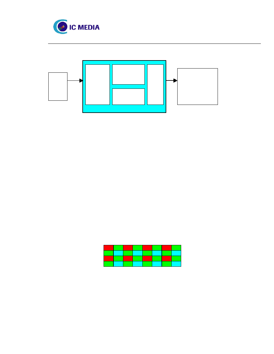
Figure 1. Block Diagram
2.1. Image Array
The image array consists of 352x288 pixels. Each pixel has a light sensitive photo diode and a set of
control and transfer transistors. At the beginning of the cycle, a row of pixels is pre-charged to its
maximum value. Then they are exposed to light for several lines worth of time and sampled by the
ADC. Correlated double sampling (CDS) is performed by subtracting the reset value (sampled right
before sampling the signal) from the signal value. The purpose of CDS is to eliminate the point-wise
fixed pattern noise (FPN). The output of CDS is approximately proportional to the amount of received
light, ranging from 0 to 255.
2.2. Color Filter
Each pixel is covered by a color filter. They form the Bayer Pattern as shown in Figure 2. (Row 0,
Column 0) is covered by a Red filter, (Row 0, Column 1) and (Row 1, Column 0) by Green filters, and
(Row 1, Column 1) by a Blue filter. Since each pixel only gets part of the frequency band, the data
needs further processing (i.e., color interpolation and color correction) in order to approximate the full
visible spectrum.
R
G
R
G
R
G
R
G
G
B
G
B
G
B
G
B
R
G
R
G
R
G
R
G
G
B
G
B
G
B
G
B
Figure 2. Color filter Bayer pattern
2.3. Exposure and Gain Control
The brightness of the scene may change by a great amount that renders the captured image either
ICM-102B
CIF Image
Sensor
5X Proprietary
Compression
Line Buffer
USB
1/7"
lens
USB Enabled
Computer