1
Micrel
ECL ProTM
SY10EPT28L
SY100EPT28L
DESCRIPTION
s
3.3V
±
10% power supply
s
Guaranteed AC parameters over temperature:
f
MAX
> 275MHz (LVTTL)
s
< 2ns LVPECL-to-LVTTL propagation delay
s
< 600ps LVTTL-to-LVPECL propagation delay
s
Internal 75k
input pull-down resistors
s
Industrial temperature range:
≠40
∞
C to +85
∞
C
s
Available in 8-pin MSOP and SOIC packages
The SY10/100EPT28L is a differential LVPECL-to-
LVTTL translator and a LVTTL-to-differential LVPECL
translator in a single package. Because LVPECL (Positive
ECL) levels are used, only +3.3V and ground are required.
The small outline 8-pin package and the dual translation
design of the EPT28L makes it ideal for applications
which are sending and receiving signals across a
backplane.
The 100K series includes temperature compensation.
Thus, logic levels are constant over temperature.
FEATURES
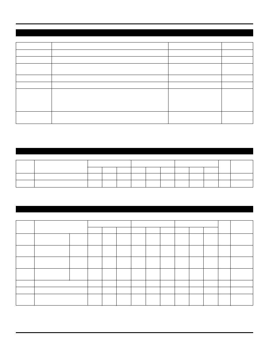
PIN CONFIGURATION/BLOCK DIAGRAM
PIN NAMES
3V LVTTL-TO-DIFFERENTIAL LVPECL
AND DIFFERENTIAL LVPECL-TO-LVTTL
TRANSLATOR
1
D_LVPECL
/D_LVPECL
Q_LVPECL
/Q-LVPECL
8
VCC
Q_LVTTL
D_LVTTL
GND
7
6
5
2
3
4
LVPECL
LVTTL
TOP VIEW
(Available in MSOP or SOIC package)
Pin
Function
D_LVTTL
Low Voltage TTL Input
Q_LVTTL
Low Voltage TTL Output
D_LVPECL
Low Voltage Differential PECL Inputs
/D_LVPECL
with 75k
internal pull-down
Q_LVPECL
Low Voltage Differential PECL Outputs
/Q_LVPECL
V
CC
3.3V Positive Supply
GND
Ground
Rev.: B
Amendment: /0
Issue Date:
October 2002
ECL ProTM
SY10EPT28L
SY100EPT28L
FINAL
ECL ProTM
ECL Pro is a trademark of Micrel, Inc.
2
ECL ProTM
SY10EPT28L
SY100EPT28L
Micrel
Symbol
Rating
Value
Unit
V
CC
Power Supply Voltage
≠0.5 to +3.8
V
V
IN
Input Voltage
0 to V
CC
V
I
OUT
LVPECL Output Current
≠Continuous
50
mV
≠Surge
100
T
A
Operating Temperature Range
≠40 to +85
∞
C
T
store
Storage Temperature Range
≠65 to +150
∞
C
JA
Package Thermal Resistance
≠Still-Air
(SOIC)
160
∞
C/W
(Junction-to-Ambient)
≠500lfpm (SOIC)
109
≠Still-Air
(MSOP)
206
∞
C/W
≠500lfpm (MSOP)
155
JC
Package Thermal Resistance
(SOIC)
39
∞
C/W
(Junction-to-Case)
(MSOP)
39
Note 1.
Permanent device damage may occur if ABSOLUTE MAXIMUM RATINGS are exceeded. This is a stress rating only and functional operation
is not implied at conditions other than those detailed in the operational sections of this data sheet. Exposure to ABSOLUTE MAXIMUM
RATlNG conditions for extended periods may affect device reliability.
ABSOLUTE MAXIMUM RATINGS
(1)
T
A
= ≠40
∞
C
T
A
= +25
∞
C
T
A
= +85
∞
C
Symbol
Parameter
Min.
Typ.
Max.
Min.
Typ.
Max.
Min.
Typ.
Max.
Unit
Condition
V
CC
Power Supply Voltage
3.0
3.3
3.6
3.0
3.3
3.6
3.0
3.3
3.6
V
I
CC
Power Supply Current
--
20
40
--
22
40
--
25
40
mA
Note 1.
10/100KEPT circuits are designed to meet the DC specifications shown in the above table after thermal equilibrium has been established. The
circuit is in a test socket or mounted on a printed circuit board and traverse airflow greater than 500lfpm is maintained.
DC ELECTRICAL CHARACTERISTICS
(1)
T
A
= ≠40
∞
C
T
A
= +25
∞
C
T
A
= +85
∞
C
Symbol
Parameter
Min.
Typ.
Max.
Min.
Typ.
Max.
Min.
Typ.
Max.
Unit
Condition
V
OH
Output HIGH
(2)
10EPT
2165
2290
2415
2230
2355
2480
2290
2415
2540
mV
Voltage
100EPT
2155
2280
2405
2155
2280
2405
2155
2280
2405
V
OL
Output LOW
(2)
10EPT
1365
1490
1615
1430
1555
1680
1490
1615
1740
mV
Voltage
100EPT
1355
1480
1605
1355
1480
1605
1355
1480
1605
V
IH
Input HIGH
(2)
10EPT
2090
--
2415
2155
--
2480
2215
--
2540
mV
Voltage
100EPT
2075
--
2420
2075
--
2420
2075
--
2420
V
IL
Input LOW
(2)
10EPT
1365
--
1690
1430
--
1755
1490
--
1815
mV
Voltage
100EPT
1355
--
1675
1355
--
1675
1355
--
1675
I
IH
Input HIGH Current
--
--
150
--
--
150
--
--
150
µ
A
V
IN
= 3.46V
I
IL
Input LOW Current
/D, D
0.5
--
0.5
--
--
0.5
--
--
0.5
µ
A
C
IN
Input Capacitance
(SOIC)
--
--
--
--
0.75
--
--
--
--
pF
(MSOP)
--
--
--
--
1.1
--
--
--
--
pF
Note 1.
10/100KEPT circuits are designed to meet the DC specifications shown in the above table after thermal equilibrium has been established. The
circuit is in a test socket or mounted on a printed circuit board and traverse airflow greater than 500lfpm is maintained.
Note 2.
Input and output parameters vary 1:1 with V
CC
.
LVPECL DC ELECTRICAL CHARACTERISTICS
(1)
V
CC
= 3.3V
±
10%
3
Micrel
ECL ProTM
SY10EPT28L
SY100EPT28L
T
A
= ≠40
∞
C
T
A
= +25
∞
C
T
A
= +85
∞
C
Symbol
Parameter
Min.
Typ.
Max.
Min.
Typ.
Max.
Min.
Typ.
Max.
Unit
Condition
V
OH
Output HIGH Voltage
2.0
--
--
2.0
--
--
2.0
--
--
V
I
OH
= ≠3mA
V
OL
Output LOW
Voltage
--
--
0.5
--
--
0.5
--
--
0.5
V
I
OH
= ≠24mA
V
IH
Input HIGH Voltage
2.0
--
--
2.0
--
--
2.0
--
--
V
V
IL
Input LOW Voltage
--
--
0.8
--
--
0.8
--
--
0.8
V
V
IK
Input Clamp Voltage
--
--
≠1.2
--
--
≠1.2
--
--
≠1.2
V
I
IK
= ≠18mA
I
IH
Input HIGH Current
--
--
20
--
--
20
--
--
20
µ
A
V
IN
= 2.7V
--
--
100
--
--
100
--
--
100
µ
A
V
IN
= V
CC
I
IL
Input LOW Current
--
--
≠0.2
--
--
≠0.2
--
--
≠0.2
µ
A
V
IN
= 0.5V
I
OUT(SC)
LVTTL Output
≠275
--
≠80
≠275
--
≠80
≠275
--
≠80
mA
V
OUT
= 0V
Short-Circuit Current
C
IN
Input Capacitance
(SOIC)
--
--
--
0.75
--
--
--
pF
(MSOP)
--
--
--
1.1
--
--
--
pF
Note 1.
10/100KEPT circuits are designed to meet the DC specifications shown in the above table after thermal equilibrium has been established. The
circuit is in a test socket or mounted on a printed circuit board and traverse airflow greater than 500lfpm is maintained.
LVTTL DC ELECTRICAL CHARACTERISTICS
(1)
V
CC
= 3.3V
±
10%
T
A
= ≠40
∞
C
T
A
= +25
∞
C
T
A
= +85
∞
C
Symbol
Parameter
Min.
Typ.
Max.
Min.
Typ.
Max.
Min.
Typ.
Max.
Unit
Condition
f
MAX
Maximum Frequency
Output
LVPECL
700
--
--
700
--
--
700
--
--
MHz
Toggle
LVTTL
275
350
--
275
350
--
275
350
--
MHz
Frequency
t
PLH
Propagation Delay
t
PHL
D_LVPECL
Q_LVTTL
1.5
--
2.5
1.5
--
2.5
1.5
--
2.5
ns
C
L
= 20pF
Q_LVTTL
D_LVPECL
100
400
600
100
400
600
100
400
600
ps
50
to V
CC
≠2.0
V
CMR
LVPECL
1.2
--
V
CC
1.2
--
V
CC
1.2
--
V
CC
V
Common Mode Range
V
PP
LVPECL Input Voltage Swing
100
--
--
100
--
--
100
--
--
mV
(Single-Ended)
(1)
LVPECL Output Rise/Fall Times
200
--
500
200
--
500
200
--
500
ns
50
to V
CC
≠2.0
t
r
,
t
f
(20% to 80%)
LVTTL Output Rise/Fall Times
0.5
--
1.0
0.5
--
1.0
0.5
--
1.0
ns
C
L
= 20pF
(10% to 90%)
t
DC
Duty Cycle
45
50
55
45
50
55
45
50
55
%
t
JITTER
Cycle-to-Cycle Jitter (rms)
--
0.2
< 1
--
0.2
< 1
--
0.2
< 1
ps
RMS
Note 1.
V
PP
(min) is the minimum input swing for which AC parameters are guaranteed.
AC ELECTRICAL CHARACTERISTICS
V
CC
= +3.3V
±
10%
4
ECL ProTM
SY10EPT28L
SY100EPT28L
Micrel
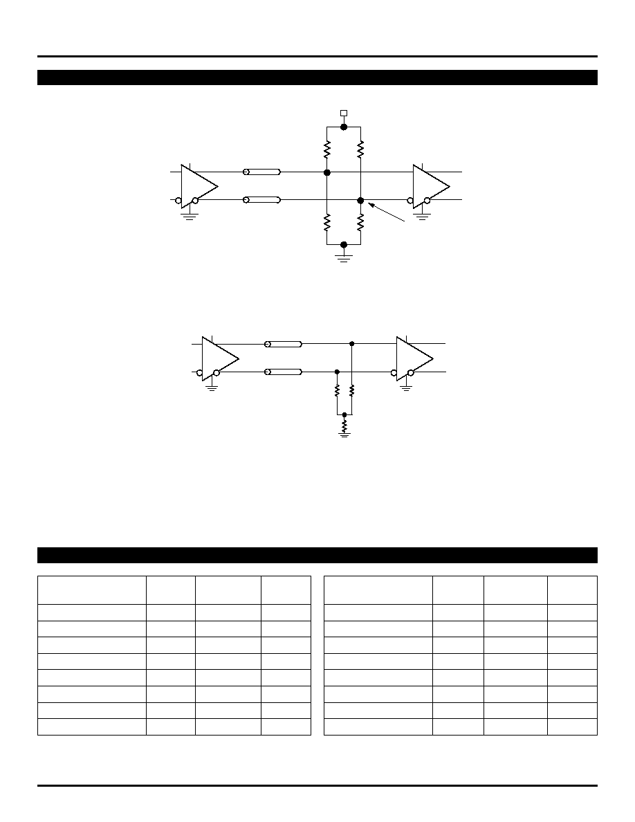
TERMINATION RECOMMENDATIONS
R2
82
R2
82
Z
O
= 50
Z
O
= 50
+3.3V
+3.3V
V
t
= V
CC
--2V
R1
130
R1
130
+3.3V
Figure 1. LVPECL Parallel Termination≠Thevenin Equivalent
Z
= 50
Z
= 50
50
50
+3.3V
+3.3V
source
destination
R
b
Figure 2. LVPECL Three-Resistor "Y≠Termination"
Note 1.
Power-saving alternative to 4-resistor, Thevenin termination.
Note 2.
Place termination resistors as close to destination inputs as possible.
Note 3.
R
b
resistor sets the DC bias voltage, equal to V
t
. For 3.3V supply, R
b
value is between 46
to 50
.
PRODUCT ORDERING CODE
Ordering
Package
Operating
Package
Code
Type
Range
Marking
SY10EPT28LZC
Z8-1
Commercial
HEP28
SY10EPT28LZCTR
(1)
Z8-1
Commercial
HEP28
SY100EPT28LZC
Z8-1
Commercial
XEP28
SY100EPT28LZCTR
(1)
Z8-1
Commercial
XEP28
SY10EPT28LKC
K8-1
Commercial
HP28
SY10EPT28LKCTR
(1)
K8-1
Commercial
HP28
SY100EPT28LKC
K8-1
Commercial
XP28
SY100EPT28LKCTR
(1)
K8-1
Commercial
XP28
Note 1.
Tape and Reel.
Note 2.
Recommended for new designs.
Ordering
Package
Operating
Package
Code
Type
Range
Marking
SY10EPT28LZI
(2)
Z8-1
Industrial
HEP28
SY10EPT28LZITR
(1, 2)
Z8-1
Industrial
HEP28
SY100EPT28LZI
(2)
Z8-1
Industrial
XEP28
SY100EPT28LZITR
(1, 2)
Z8-1
Industrial
XEP28
SY10EPT28LKI
(2)
K8-1
Industrial
HP28
SY10EPT28LKITR
(1, 2)
K8-1
Industrial
HP28
SY100EPT28LKI
(2)
K8-1
Industrial
XP28
SY100EPT28LKITR
(1, 2)
K8-1
Industrial
XP28
5
Micrel
ECL ProTM
SY10EPT28L
SY100EPT28L
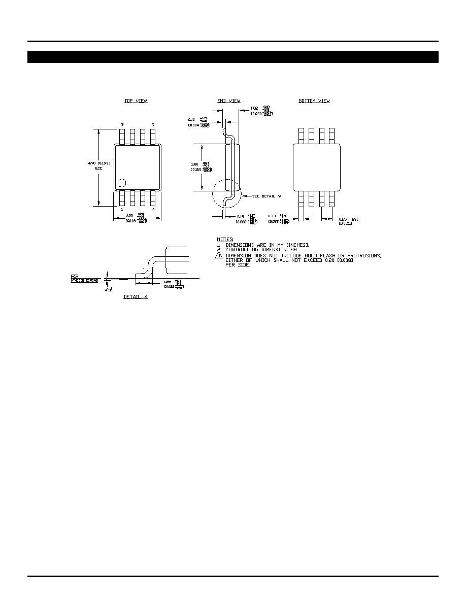
8 LEAD MSOP (K8-1)
Rev. 01