INTERNET
http://www.minicircuits.com
P.O. Box 350166, Brooklyn, New York 11235-0003 (718) 934-4500 Fax (718) 332-4661
Distribution Centers NORTH AMERICA 800-654-7949 ∑ 417-335-5935 ∑ Fax 417-335-5945 ∑ EUROPE 44-1252-832600 ∑ Fax 44-1252-837010
Mini-Circuits
Æ
Mini-Circuits ISO 9001 & ISO 14001 Certified
A
B
C
D
E
F
G
.390
.31
.225
.060
--
.100
.045
9.91
7.87
5.72
1.52
--
2.54
1.14
H
J
K
L
M
wt
.420
.120
.060
.100
--
grams
10.67
3.05
1.52
2.54
--
0.50
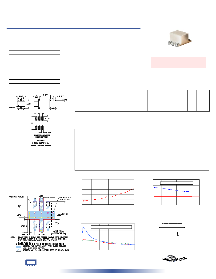
75 5 to 600 MHz
Directional Coupler
Surface Mount
CASE STYLE: QQQ569
PRICE: $11.95 ea. QTY (1-9)
Demo Board MCL P/N: TB-34
Suggested PCB Layout (PL-043)
Outline Dimensions ( )
inch
mm
Maximum Ratings
Pin Connections
INPUT
6
OUTPUT
1
COUPLED
4
GROUND
2,5
ISOLATE (DO NOT USE)
3
Outline Drawing
Directional Coupler Electrical Specifications
Typical Performance Data
+ RoHS compliant in accordance
with EU Directive (2002/95/EC)
The +Suffix identifies RoHS Compliance. See our web site
for RoHS Compliance methodologies and qualifications.
LRDC-12-1-75J+
LRDC-12-1-75J
Operating Temperature
-40∞C to 85∞C
Storage Temperature
-55∞C to 100∞C
Features
∑ low insertion loss, 0.5 dB typ.
∑ high directivity, 21 dB typ.
∑ aqueous washable
∑ J-leads for strain relief and excellent solderability
Applications
∑ VHF/UHF
∑ signal sampling
∑ communications
∑ cable tv
LRDC-12-1-75J
MAINLINE LOSS
0.6
0.7
0.8
0.9
1.0
1.1
0
100
200
300
400
500
600
FREQUENCY (MHz)
MAINLINE
LOSS
(dB)
at RF level of -10 dBm
LRDC-12-1-75J
COUPLING & DIRECTIVITY
0
10
20
30
40
0
100
200
300
400
500
600
FREQUENCY (MHz)
COUPLING
&
DIRECTIVITY
(dB)
DIRECTIVITY
COUPLING
at RF level of -10 dBm
LRDC-12-1-75J
RETURN LOSS
10
20
30
40
50
0
100
200
300
400
500
600
FREQUENCY (MHz)
R
E
T
U
R
N
L
O
S
S
(
d
B
)
IN
OUT
CPL
at RF level of -10 dBm
electrical schematic
INPUT
OUTPUT
COUPLED
Frequency
(MHz)
Mainline Loss
(dB)
In-Out
Coupling
(dB)
In-Cpl
Directivity
(dB)
In
Return Loss
(dB)
Out
Cpl
REV. B
M102713
LRDC-12-1-75J
WZ/TD/CP
060718
SUGGESTED LAYOUT FOR
PCB LAND PATTERN
5.00
0.68
12.25
27.30
24.93
36.02
24.62
6.00
0.67
12.24
27.29
25.25
37.90
24.76
8.00
0.66
12.24
27.30
25.59
41.55
24.92
10.00
0.67
12.24
27.29
25.75
45.26
24.96
100.00
0.69
12.26
25.97
24.35
29.52
24.21
200.00
0.71
12.27
23.92
21.73
23.91
23.15
300.00
0.77
12.28
22.07
19.81
20.80
21.77
400.00
0.79
12.20
20.71
18.62
19.03
20.45
500.00
0.84
12.11
19.85
18.13
18.22
19.44
600.00
0.92
12.05
19.38
18.26
18.28
18.73
FREQ.
(MHz)
COUPLING
(dB)
MAINLINE LOSS
1
(dB)
DIRECTIVITY
(dB)
VSWR
(:1)
POWER
INPUT, W
Nom. Flatness
L
M
U
L
M
U
L
MU
f
L
-f
U
Typ. Max. Typ. Max. Typ. Max. Typ. Min. Typ. Min. Typ. Min.
Typ.
Max. Max.
5-600
12.2±0.5
±0.6
0.4
0.8
0.5
1.0
0.8
1.5
20
17
21
18
20
12
1.3
1.0
1.0
L = low range [f
L
to 10 f
L
] M = mid range [10 f
L
to f
U
/2] U = upper range [f
U
/2 to f
U
]
1. Mainline loss includes therotertical power loss at coupled port.