LM64
±
1∞C Remote Diode Temperature Sensor with PWM Fan
Control and 5 GPIO's
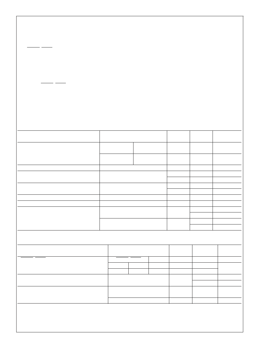
General Description
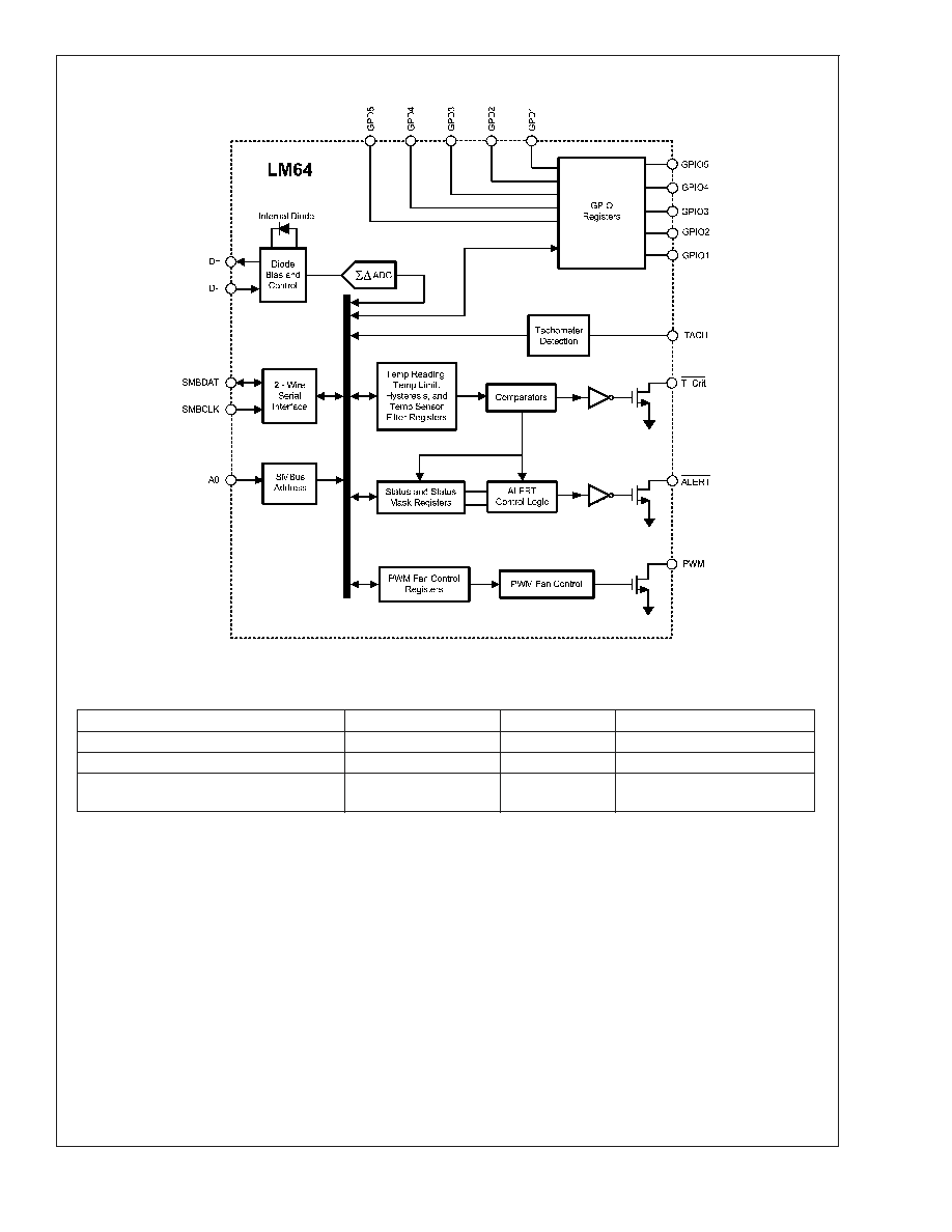
The LM64 is a remote diode temperature sensor with PWM
fan control. The LM64 accurately measures its own tempera-
ture and that of a remote diode. The LM64 remote tempera-
ture accuracy is factory trimmed for a MMBT3904 diode-
connected
transistor
with
a
16∞C
offset
for
high
temperatures. T
ACTUAL DIODE JUNCTION
= T
LM64
+ 16∞C
The LM64 features a PWM, open-drain, fan control output, 5
GPIO (General Purpose Input/Output) and 5 GPD (General
Purpose Default) pins. The 8-step Lookup Table allows for a
non-linear fan speed vs. temperature transfer function often
used to quiet acoustic fan noise.
Features
n
Accurately senses remote and local diode temperatures
n
Integrated PWM fan speed control output
n
Programmable 8-step Lookup Table for quieting fans
n
ALERT and T_Crit open-drain outputs
n
Tachometer input for measuring fan RPM
n
10 bit plus sign remote diode temperature data format,
with 0.125∞C resolution
n
SMBus 2.0 compatible interface, supports TIMEOUT
n
5 General Purpose Input/Output pins
n
5 General Purpose Default input pins
n
24-pin LLP package
Key Specifications
n
Remote Diode Temperature Accuracy (includes
quantization error)
Ambient Temp
Diode Temp
Max Error
30∞C to 50∞C
120∞C to 140∞C
±
1.0∞C (max)
0∞C to 85∞C
25∞C to 140∞C
±
3.0∞C (max)
n
Local Temp Accuracy (includes quantization error)
Ambient Temp
Max Error
25∞C to 125∞C
±
3.0∞C (max)
n
Power Supply Requirements
Supply DC Voltage
3.0 V to 3.6 V
Supply DC Current
1.1 mA (typ)
Applications
n
Computer Processor Thermal Management
n
Graphics Processor Thermal Management
n
Voltage Regulator Modules
n
Electronic Instrumentation
n
Power Supplies
n
Projectors
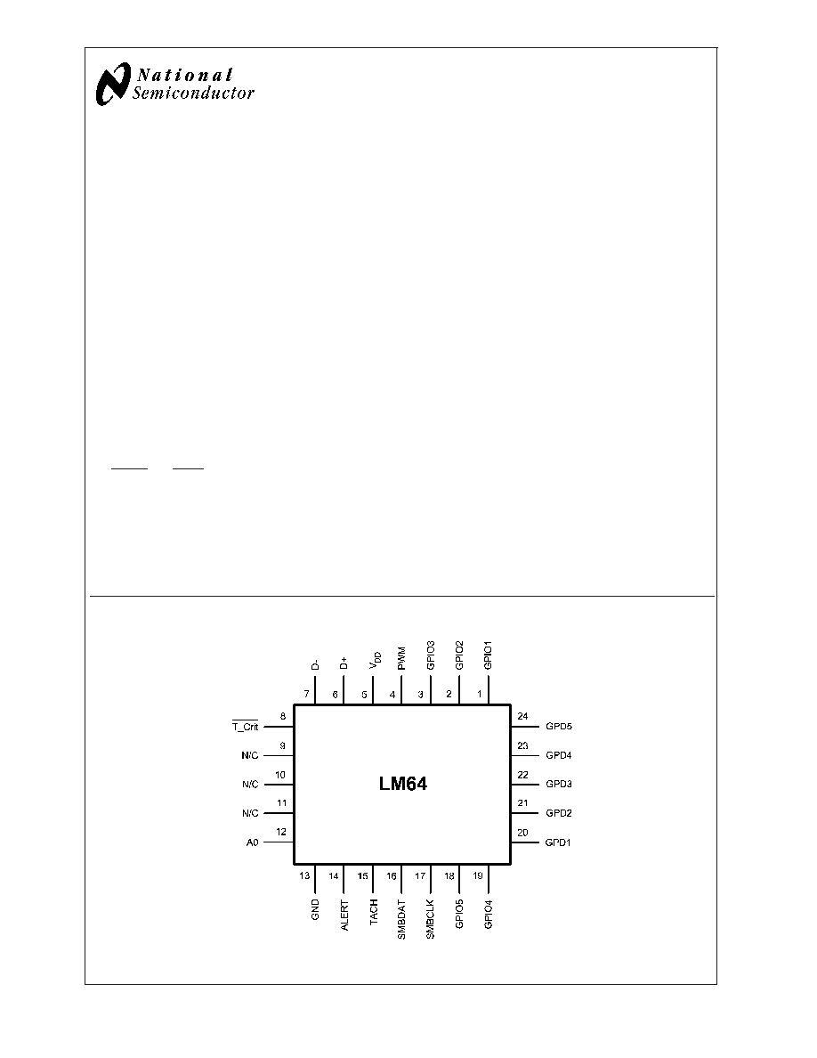
Connection Diagram
20065501
December 2003
LM64
±
1∞C
Remote
Diode
T
emperature
Sensor
with
PWM
Fan
Control
and
5
GPIO'
s
© 2003 National Semiconductor Corporation
DS200655
www.national.com
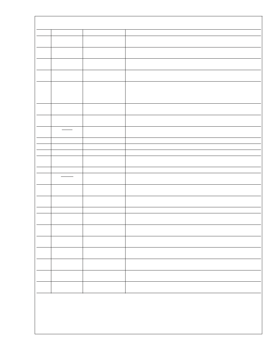
Pin Descriptions
Pin
Name
Input/Output
Function and Connection
1
GPIO1
Digital Input/
Open-Drain Output
General Purpose Open-Drain Digital Output or Digital Input. Typical pull-up
resistor is 10 k
to V
DD
.
2
GPIO2
Digital Input/
Open-Drain Output
General Purpose Open-Drain Digital Output or Digital Input. Typical pull-up
resistor is 10 k
to V
DD
.
3
GPIO3
Digital Input/
Open-Drain Output
General Purpose Open-Drain Digital Output or Digital Input. Typical pull-up
resistor is 10 k
to V
DD
.
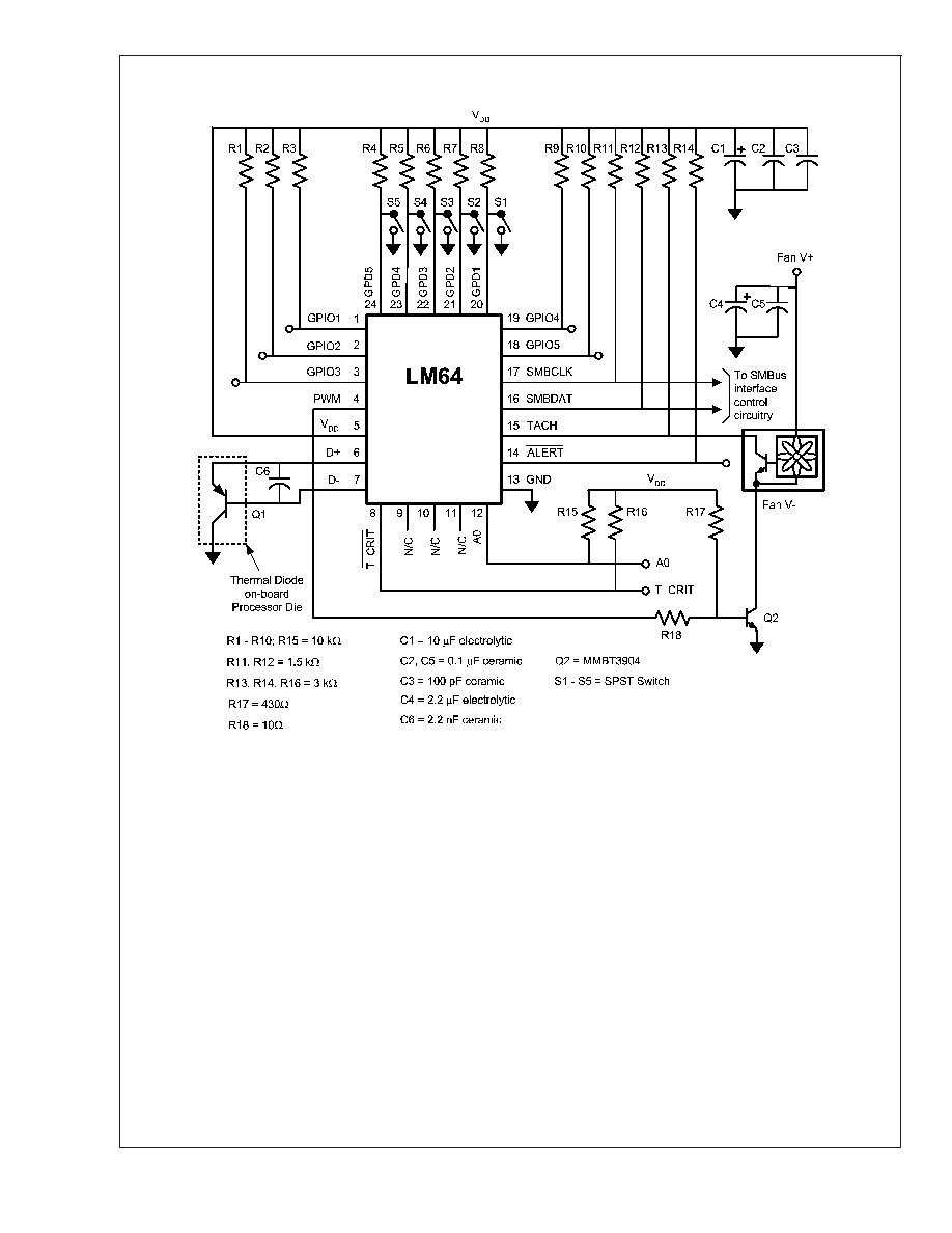
4
PWM
Open-Drain
Digital Output
Open-Drain Digital Output. Connect to fan drive circuitry. The power-on
default for this pin is low (pin 4 pulled to ground).
5
V
DD
Power Supply Input
Connect to a low-noise +3.3
±
0.3 VDC power supply, and bypass to GND
with a 0.1 µF ceramic capacitor in parallel with a 100 pF ceramic capacitor.
A bulk capacitance of 10 µF needs to be in the vicinity of the LM64's V
DD
pin.
6
D+
Analog Input
Connect to the anode (positive side) of the remote diode. A 2.2 nF ceramic
capacitor must be connected between pins 6 and 7.
7
D-
Analog Input
Connect to the cathode (negative side) of the remote diode. A 2.2 nF
ceramic capacitor must be connected between pins 6 and 7.
8
T_Crit
Open-Drain
Digital Output
Open-Drain Digital Output. Typical pull-up resistor is 3 k
to V
DD
.
9
N/C
N/A
No Connection.
10
N/C
N/A
No Connection.
11
N/C
N/A
No Connection.
12
A0
Digital Input
SMBus Address Select pin. If High, the SMBus address is 0x4E or, if Low,
the SMBus address is 0x18. Typical pull-up resistor is 10 k
to V
DD
.
13
GND
Ground
This is the analog and digital ground return.
14
ALERT
Open-Drain
Digital Output
This pin is an open-drain ALERT Output. Typical pull-up resistor is 3 k
to
V
DD
.
15
TACH
Digital Input
This pin is a digital tachometer input. Typical pull-up resistor is 3 k
to
V
DD
.
16
SMBDAT
Digital Input/
Open-Drain Output
This is the bi-directional SMBus data line. Typical pull-up resistor is 1.5 k
to V
DD
.
17
SMBCLK
Digital Input
This is the SMBus clock input. Typical pull-up resistor is 1.5 k
to V
DD
.
18
GPIO5
Digital Input/
Open-Drain Output
General Purpose Open-Drain Digital Output or Digital Input. Typical pull-up
resistor is 10 k
to V
DD
.
19
GPIO4
Digital Input/
Open-Drain Output
General Purpose Open-Drain Digital Output or Digital Input. Typical pull-up
resistor is 10 k
to V
DD
.
20
GPD1
Digital Input
General Purpose Default Input Pin. Typical pull-up resistor is 10 k
to V
DD
.
Always connect to a logical High or Low level.
21
GPD2
Digital Input
General Purpose Default Input Pin. Typical pull-up resistor is 10 k
to V
DD
.
Always connect to a logical High or Low level.
22
GPD3
Digital Input
General Purpose Default Input Pin. Typical pull-up resistor is 10 k
to V
DD
.
Always connect to a logical High or Low level.
23
GPD4
Digital Input
General Purpose Default Input Pin. Typical pull-up resistor is 10 k
to V
DD
.
Always connect to a logical High or Low level.
24
GPD5
Digital Input
General Purpose Default Input Pin. Typical pull-up resistor is 10 k
to V
DD
.
Always connect to a logical High or Low level.
LM64
www.national.com
2
Absolute Maximum Ratings
(Notes 1,
2)
Supply Voltage, V
DD
-0.3 V to 6.0 V
Voltage on SMBDAT, SMBCLK,
ALERT, T_Crit, PWM Pins
-0.5 V to 6.0 V
Voltage on Other Pins
-0.3 V to (V
DD
+ 0. 3 V)
Input Current, D- Pin
±
1 mA
Input Current at All Other Pins (Note 3)
5 mA
Package Input Current (Note 3)
30 mA
Package Power Dissipation
(Note 5)
SMBDAT, ALERT, T_Crit, PWM pins
Output Sink Current
10 mA
Storage Temperature
-65∞C to +150∞C
ESD Susceptibility (Note 4)
Human Body Model
2000 V
Machine Model
200 V
SMT Soldering Information
See National Semiconductor Application Note AN-1187,
"Leadless Leadframe Package" for information on SMT
Assembly using LLP Packages. This is available at
http://www.national.com/an/AN/AN-1187.pdf.
Operating Ratings
(Notes 1, 2)
LM64 Operating Temperature Range
0∞C
T
A
+85∞C
Remote Diode Temperature Range
25∞C
T
D
+140∞C
Electrical Characteristics
T
MIN
T
A
T
MAX
Supply Voltage Range (V
DD
)
+3.0 V to +3.6 V
DC Electrical Characteristics
TEMPERATURE-TO-DIGITAL CONVERTER CHARACTERISTICS The following specifications apply for V
DD
= 3.0 VDC to
3.6 VDC, and all analog source impedance R
S
= 50
unless otherwise specified in the conditions. Boldface limits apply for
T
A
= T
MIN
to T
MAX
; all other limits T
A
= +25∞C.
Parameter
Conditions
Typical
(Note 7)
Limits
(Note 8)
Units
(Limits)
Temperature Error using a diode-connected
MMBT3904 transistor. T
D
is the Remote
Diode Junction Temperature.
T
D
= T
LM64
+ 16∞C
T
A
= +30∞C to
+50∞C
T
D
= +120∞C to
+140∞C
±
1
∞C (max)
T
A
= +0∞C to
+85∞C
T
D
= +25∞C to
+140∞C
±
3
∞C (max)
Temperature Error Using the Local Diode
T
A
= +25∞C to +125∞C (Note 10)
±
1
±
3
∞C (max)
Remote Diode Resolution
11
Bits
0.125
∞C
Local Diode Resolution
8
Bits
1
∞C
Conversion Time of All Temperatures
Fastest Setting
31.25
34.4
ms (max)
D- Source Voltage
0.7
V
Diode Source Current
(V
D+
- V
D-
) = +0.65 V; High
Current
160
315
µA (max)
110
µA (min)
Low Current
13
20
µA (max)
7
µA (min)
Operating Electrical Characteristics
Parameter
Conditions
Typ
(Note 7)
Limits
(Note 8)
Units
ALERT, T_Crit and PWM Output Saturation
Voltage
ALERT, T_Crit
PWM
I
OUT
4 mA
6 mA
0.4
V (max)
I
OUT
6 mA
0.55
Power-On-Reset Threshold Voltage
2.4
V (max)
1.8
V (min)
Supply Current (Note 9)
SMBus Inactive, 16 Hz
Conversion Rate
1.1
2.0
mA (max)
STANDBY Mode
320
µA
LM64
www.national.com
5