 | –≠–ª–µ–∫—Ç—Ä–æ–Ω–Ω—ã–π –∫–æ–º–ø–æ–Ω–µ–Ω—Ç: 134RLP5 | –°–∫–∞—á–∞—Ç—å:  PDF PDF  ZIP ZIP |

www.vishay.com
For technical questions contact: aluminumcaps1@vishay.com
Document Number: 28307
88
Revision: 10-Mar-05
134 RLP 5
Vishay BCcomponents
Aluminum Capacitors
Radial Low Profile 5 mm
FEATURES
∑
Polarized aluminum electrolytic capacitors,
non-solid electrolyte
∑
Radial leads, cylindrical aluminum case,
insulated with a blue vinyl sleeve
∑
Charge and discharge proof
∑
Very low profile, 5 mm height
∑
Extremely miniaturized.
∑
Dimensions 3 x 5 and 3.5 x 5 mm are not available in Lead
(Pb)-free. For Lead (Pb)-free version, please use the next
4 x 5 mm product instead.
APPLICATIONS
∑
General purpose, industrial, automotive and audio-video
∑
Coupling, decoupling, smoothing, filtering and timing
∑
High mounting density
∑
Portable and mobile equipment
(very small size and very low mass), low profile equipment.
MARKING
The capacitors are marked (where possible)
with the following information:
∑
Rated capacitance (in
µ
F)
∑
Rated voltage (in V)
∑
Negative terminal identification
∑
Code indicating factory of origin
∑
Name of manufacturer
∑
Date code, in accordance with IEC 60062.
∑
Series number (134)
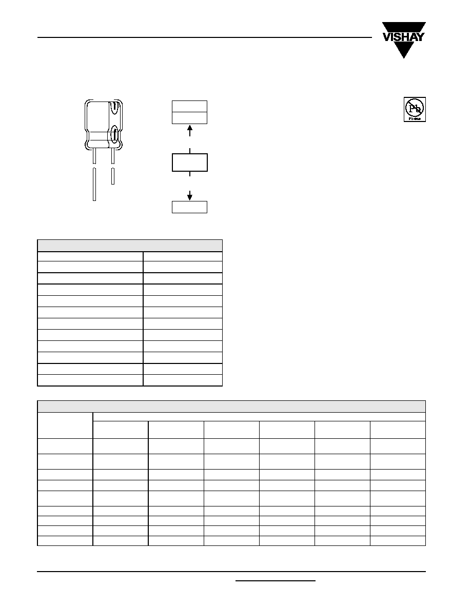
134 RLP 5
5 mm
097 RLP 7
038 RSU
153 CLV
higher
CV-values
Longer life
SMD
Fig.1 Component outline.
QUICK REFERENCE DATA
DESCRIPTION
VALUE
Nominal case sizes (
D
◊
L in mm)
3
◊
5 to 6.3
◊
5
Rated capacitance range, C
R
1.0 to 100
µ
F
Tolerance on C
R
±
20%
Rated voltage range, U
R
6.3 to 50 V
Category temperature range
-
40 to +85
∞
C
Endurance test at 85
∞
C
1000 hours
Useful life at 85
∞
C
1500 hours
Useful life at 40
∞
C, 1.4
◊
IR applied
40 000 hours
Shelf life at 0 V, 85
∞
C
500 hours
Based on sectional specification
IEC 60384-4/EN130300
Climatic category IEC 60068
40/085/56
Note
1)
Lead (Pb)-free not available - please select next case size 4 x 5 for Lead (Pb)-free version.
SELECTION CHART FOR C
R
, U
R
AND RELEVANT NOMINAL CASE SIZES
(
D
◊
L in mm)
C
R
(
µ
F)
U
R
(V)
6.3
10
16
25
35
50
1.0
-
-
-
-
-
3
◊
5
1)
4
◊
5
2.2
-
-
-
-
3
◊
5
1)
3.5
◊
5
1)
4
◊
5
3.3
-
-
-
3
◊
5
1)
-
4
◊
5
4.7
-
-
-
3.5
◊
5
1)
4
◊
5
5
◊
5
10
-
-
3.5
◊
5
1)
4
◊
5
-
5
◊
5
6.3
◊
5
22
4
◊
5
-
5
◊
5
-
6.3
◊
5
-
33
-
5
◊
5
-
6.3
◊
5
-
-
47
5
◊
5
-
6.3
◊
5
-
-
-
100
6.3
◊
5
-
-
-
-
-

Document Number: 28307
For technical questions contact: aluminumcaps1@vishay.com
www.vishay.com
Revision: 10-Mar-05
89
134 RLP 5
Aluminum Capacitors
Radial Low Profile 5 mm
Vishay BCcomponents
DIMENSIONS
in millimeters
AND AVAILABLE FORMS
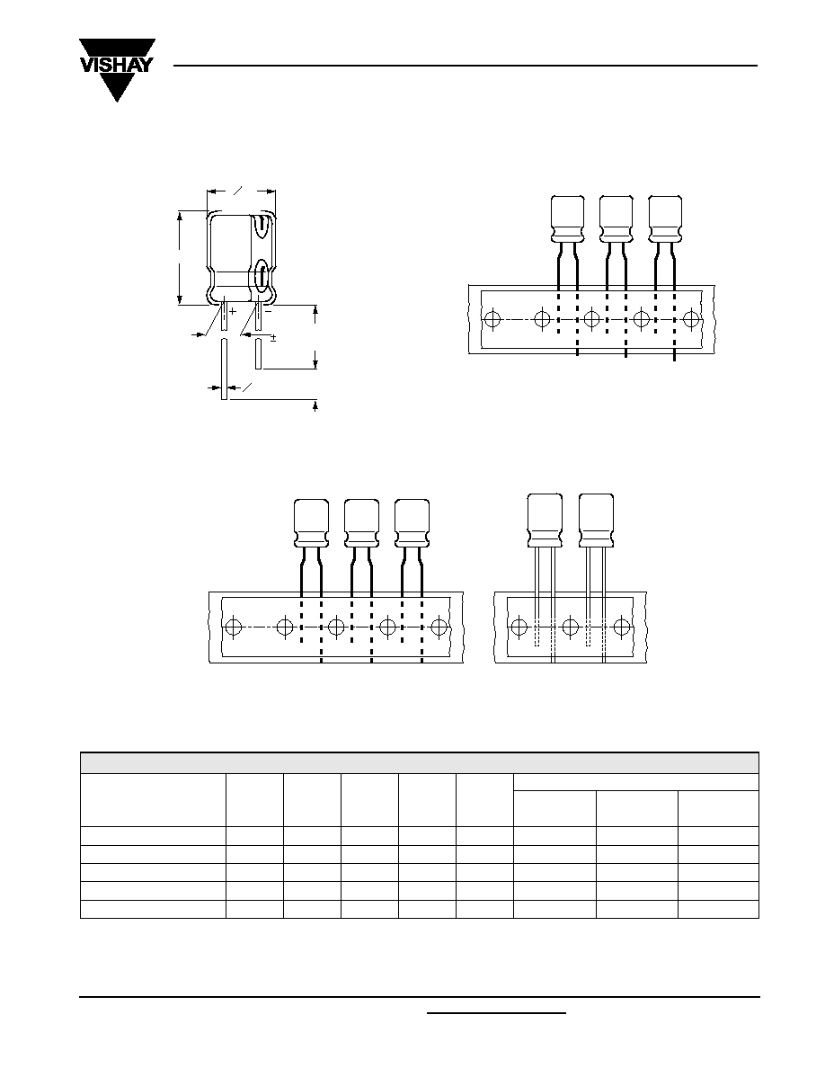
O D
L
O d
F
0.5
15
min
5
min
Fig.2 Form CA: Long leads.
Case ÿD = 3 and 3.5 mm; pitch F = 2.5mm
Case ÿD = 4 to 6.3 mm; pitch F = 5 mm
Fig.3 Form TFA: Taped in box (ammopack)
pitch F = 2.5 mm.
Case
D = 4 to 6.3 mm.
Fig.4 Form TNA: Taped in box (ammopack).
Table 1
Note
1)
Lead (Pb)-free not available - please select next case size 4 x 5 for Lead (Pb)-free version.
Detailed tape dimensions see section `PACKAGING'.
DIMENSIONS
in millimeters
AND PACKAGING QUANTITIES
NOMINAL CASE SIZE
D
◊
L
CASE
CODE
d
D
max
L
max
F
PACKAGING QUANTITIES
FORM
CA
FORM
TFA
FORM
TNA
3 x 5
1)
52
0.40
3.5
6.0
1.0 ±0.3
3000
3000
≠
3.5 x 5
1)
52
0.40
4.0
6.0
1.0
±
0.3
3 000
3 000
-
4 x 5
53
0.45
4.5
6.0
1.5
±
0.5
2 000
2 000
2000
5 x 5
54
0.45
5.5
6.0
2.0
±
0.5
2 000
2 000
2000
6.3 x 5
55
0.45
6.8
6.0
2.5
±
0.5
2 000
2 000
2000

134 RLP 5
Vishay BCcomponents
Aluminum Capacitors
Radial Low Profile 5 mm
www.vishay.com
For technical questions contact: aluminumcaps1@vishay.com
Document Number: 28307
90
Revision: 10-Mar-05
.
Note
1.
Unless otherwise specified, all electrical values in Table apply
at T
amb
= 20
∞
C, P = 86 to 106 kPa, RH = 45 to 75%
ELECTRICAL DATA
SYMBOL
DESCRIPTION
C
R
rated capacitance at 120 Hz, tolerance
±
20%
I
R
rated RMS ripple current at 120 Hz, 85
∞
C
I
L2
max. leakage current after 2 minutes at U
R
Tan
max. dissipation factor at 120 Hz
Z
max. impedance at 100 kHz
ORDERING EXAMPLE
Electrolytic capacitor 134 series
22
µ
F/16 V;
±
20%
Nominal case size:
5
◊
5 mm; Form TFA
Catalog number: 2222 134 35229.
1)
Lead (Pb)-free not available - please select next case size 4 x 5 for Lead (Pb)-free version.
ELECTRICAL DATA AND ORDERING INFORMATION
U
R
(V)
C
R
120 Hz
(
µ
F)
NOMINAL
CASE SIZE
D
◊
L
(mm)
I
R
120 Hz
85
∞
C
(mA)
I
L2
2 min
(
µ
A)
Tan
120 Hz
Z
100 kHz
(
)
CATALOG NUMBER
2222 134 .....
BULK
LONG LEADS
TAPED
AMMOPACK
FORM
CA
F
(mm)
FORM
TFA
F
(mm)
FORM
TNA
F
(mm)
6.3
22
4
◊
5
23
3
0.24
11
53229
1.5
33229
5.0
73229
2.5
47
5
◊
5
38
3
0.24
5.2
53479
2.0
33479
5.0
73479
2.5
100
6.3
◊
5
60
7
0.24
3.4
53101
2.5
33101
5.0
73101
2.5
10
33
5
◊
5
35
4
0.20
6.0
54339
2.0
34339
5.0
74339
2.5
16
10
3.5
◊
5
17
3
0.16
17
55109
1)
1.0
35109
1)
2.5
-
-
10
4
◊
5
20
3
0.16
12
95105
1.5
95103
5.0
95107
2.5
22
5
◊
5
32
4
0.16
6.4
55229
2.0
35229
5.0
75229
2.5
47
6.3
◊
5
50
8
0.16
4.2
55479
2.5
35479
5.0
75479
2.5
25
3.3
3
◊
5
9.5
3
0.14
24
56338
1)
1.0
36338
1)
2.5
-
-
4.7
3.5
◊
5
12
3
0.14
19
56478
1)
1.0
36478
1)
2.5
-
-
33
6.3
◊
5
45
9
0.14
4.6
56339
2.5
36339
5.0
76339
2.5
35
2.2
3
◊
5
8.3
3
0.12
41
50228
1)
1.0
30228
1)
2.5
-
-
4.7
4
◊
5
15
3
0.12
27
50478
1.5
30478
5.0
70478
2.5
10
5
◊
5
25
4
0.12
17
50109
2.0
30109
5.0
70109
2.5
22
6.3
◊
5
40
8
0.12
11
50229
2.5
30229
5.0
70229
2.5
50
1.0
3
◊
5
6.2
3
0.10
50
51108
1)
1.0
31108
1)
2.5
-
-
1.0
4
◊
5
7.5
3
0.10
28
91105
1.5
91103
5.0
91107
2.5
2.2
3.5
◊
5
10
3
0.10
33
51228
1)
1.0
31228
1)
2.5
-
-
2.2
4
◊
5
12
3
0.10
26
91225
1.5
91223
5.0
91227
2.5
3.3
4
◊
5
14
3
0.10
25
51338
1.5
31338
5.0
71338
2.5
4.7
5
◊
5
19
3
0.10
22
51478
2.0
31478
5.0
71478
2.5
10
6.3
◊
5
29
5
0.10
14
51109
2.5
31109
5.0
71109
2.5
ADDITIONAL ELECTRICAL DATA
DESCRIPTION
CONDITIONS
VALUE
VOLTAGE
Surge voltage
U
s
1.15
◊
U
R
Reverse voltage
U
rev
1 V
CURRENT
Leakage current
after 2 minutes at U
R
I
L2
0.01C
R
◊
U
R
or 3
µ
A (whichever is greater)
RESISTANCE
Equivalent series resistance (ESR)
calculated from tan
max
and C
R
(see Table )
ESR = tan
/ 2
fC
R

Document Number: 28307
For technical questions contact: aluminumcaps1@vishay.com
www.vishay.com
Revision: 10-Mar-05
91
134 RLP 5
Aluminum Capacitors
Radial Low Profile 5 mm
Vishay BCcomponents
RIPPLE CURRENT AND USEFUL LIFE
3.3
3.2
3.0
2.8
2.6
2.4
2.2
2.0
1.8
1.6
1.4
1.2
1.0
0.8
0.5
0.0
3.1
40
50
60
70
80
90
100
T
amb
(
∞
C)
lifetime multiplier
(1)
70
50
4.0
6 .0
2.0
1.5
30
15
10
3.0
20
1.0
I
A
I
R
CCC205
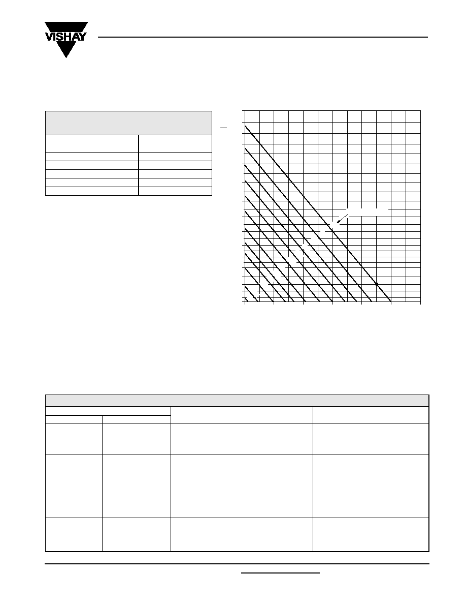
Fig.5 Multiplier of useful life as a function of ambient temperature and ripple current load.
I
A
= actual ripple current at 120 Hz.
I
R
= rated ripple current at 120 Hz, 85
∞
C.
(1) Useful life at 85
∞
C and I
R
applied: 1500 hours.
Table 2
MULTIPLIER OF RIPPLE CURRENT (I
R
)
AS A FUNCTION OF FREQUENCY
FREQUENCY
(HZ)
I
R
MULTIPLIER
50
0.60
120
1.00
400
1.20
800
1.30
2 000
1.40
Table 3
TEST PROCEDURES AND REQUIREMENTS
TEST
PROCEDURE
(quick reference)
REQUIREMENTS
NAME OF TEST
REFERENCE
Endurance
IEC 60384-4/
EN130300,
subclause 4.13
T
amb
= 85
∞
C; U
R
applied;
1 000 hours
C/C:
±
20%
tan
2
◊
spec. limit
I
L2
spec. limit
Useful life
CECC 30301,
subclause 1.8.1
T
amb
= 85
∞
C; U
R
and I
R
applied;
1 500 hours
C/C:
±
50%
tan
3
◊
spec. limit
Z
3
◊
spec. limit
I
L2
spec. limit
no short or open circuit
total failure percentage:
3%
Shelf life
(storage at high
temperature)
IEC 60384-4/
EN130300,
subclause 4.17
T
amb
= 85
∞
C; no voltage applied;
500 hours
after test: U
R
to be applied for 30 minutes,
24 to 48 hours before measurement
C/C, tan
, Z:
for requirements
see `Endurance test' above
I
L2
spec. limit


